
Additive manufacturing, commonly known as 3D printing, has evolved significantly since its inception in the 1980s, transitioning from a niche prototyping tool to a transformative technology across industries such as aerospace, automotive, construction, and healthcare. Central to this evolution are the mechanical systems that dictate the movement and precision of the print head: robotic arms and gantry systems. These two approaches represent distinct paradigms in 3D printing, each with unique kinematic properties, operational characteristics, and application domains. This article provides a detailed comparison of robotic arms and gantry systems in the context of 3D printing, exploring their mechanical principles, advantages, limitations, and suitability for various scientific and industrial purposes.
3D printing operates on the principle of layer-by-layer material deposition, guided by digital models typically encoded in formats such as STL (Stereolithography) files. The precision, speed, and flexibility of this process depend heavily on the motion control system employed. Gantry systems, rooted in Cartesian coordinate mechanics, have long been the standard in desktop and industrial 3D printers due to their simplicity and reliability. In contrast, robotic arms, derived from industrial robotics, offer multi-axis flexibility and have gained traction in large-scale and non-planar printing applications. Understanding the differences between these systems requires an examination of their design, kinematics, material handling capabilities, and practical implications.
Robotic Arms in 3D Printing
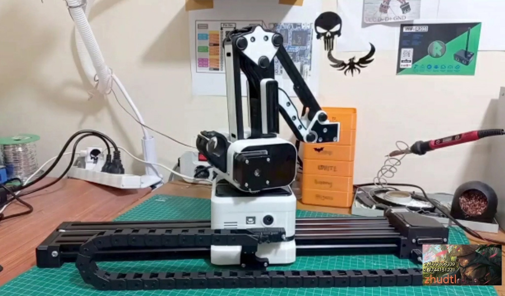
A robotic arm in 3D printing is typically an articulated manipulator with multiple degrees of freedom (DoF), often ranging from 4 to 6 axes, though some advanced systems may incorporate additional axes via external mechanisms like rails or rotary tables. These arms consist of a series of rigid links connected by rotary or prismatic joints, each driven by servo motors or stepper motors under precise control. The print head, whether an extruder for fused deposition modeling (FDM), a nozzle for concrete printing, or a laser for directed energy deposition (DED), is mounted at the end effector, allowing material deposition in a wide range of orientations.
The kinematics of a robotic arm are governed by forward and inverse kinematic equations. Forward kinematics determine the position and orientation of the end effector given joint angles, while inverse kinematics calculate the required joint angles to achieve a desired position. For a 6-axis robotic arm, the workspace is a complex, non-linear volume—often approximated as a toroidal or spherical envelope—limited by the arm’s reach, typically 1-3 meters for industrial models like the KUKA KR Quantec or ABB IRB 6700. This reach can be extended by mounting the arm on a linear track or mobile base, as seen in construction applications.
Robotic arms excel in flexibility, enabling non-planar printing paths that deviate from the traditional layer-by-layer approach of Cartesian systems. This capability is particularly valuable in applications requiring complex geometries, such as organic forms in architecture or multi-material components in aerospace. For instance, the MX3D project utilizes a 6-axis robotic arm to print metal structures via wire-arc additive manufacturing (WAAM), achieving intricate lattice designs unfeasible with conventional methods. Similarly, in construction, companies like Branch Technology employ robotic arms to extrude polymer composites, creating freeform architectural elements.
However, robotic arms face challenges in precision and speed. Their multi-joint design introduces cumulative positional errors, exacerbated by factors like joint backlash, thermal expansion, and payload-induced deflection. Modern systems mitigate these issues with advanced control algorithms, such as those incorporating real-time feedback from laser trackers or vision systems, yet they generally exhibit lower path accuracy compared to rigid Cartesian setups. Additionally, the maximum deposition rate is constrained by the arm’s payload capacity—typically 10-50 kg for mid-range models—limiting the size of the extruder or print head.
Gantry Systems in 3D Printing
A gantry system, also known as a Cartesian or orthogonal printer, operates on a linear motion framework defined by three primary axes: X (left-right), Y (front-back), and Z (up-down). The print head is mounted on a carriage that moves along rails or beams, driven by belts, lead screws, or linear actuators, with stepper motors providing precise control. This configuration resembles a bridge crane, where the gantry spans the build volume, offering a rectangular or cubic workspace. Common examples include desktop printers like the Prusa i3 and large-scale systems like the COBOD BOD2 construction printer.
The kinematics of a gantry system are straightforward, relying on linear interpolation along orthogonal axes. The position of the print head is directly mapped to Cartesian coordinates, simplifying toolpath generation and reducing computational overhead. The build volume is explicitly defined by the physical dimensions of the frame, which can range from a few centimeters in hobbyist printers to tens of meters in industrial or construction-grade systems. For instance, the ICON Vulcan printer, a gantry-based concrete printer, boasts a build area of 8.5 m wide by 3.5 m high, scalable with modular extensions.
Gantry systems are renowned for their stability and precision, owing to their rigid structure and minimal moving parts. The fixed frame minimizes vibrations and deflections, ensuring high repeatability—often within ±0.1 mm for industrial models. This makes them ideal for applications requiring consistent layer thickness and surface finish, such as FDM printing of functional prototypes or large-scale concrete printing of structural walls. Their linear motion also facilitates higher print speeds, with deposition rates exceeding 100 kg/hour in some polymer printers and up to 1 m³/hour in concrete systems.
However, gantry systems lack the flexibility of robotic arms. Their motion is confined to planar layers, restricting the ability to print overhangs beyond a certain angle (typically 45-60°) without support structures. The build volume, while large, is fixed by the frame’s dimensions, requiring significant space and infrastructure for oversized prints. Additionally, the initial cost and setup complexity can be substantial, particularly for large-scale systems used in construction or aerospace.
Comparative Analysis
To elucidate the differences between robotic arms and gantry systems, a detailed comparison across key parameters is warranted. These parameters include flexibility, precision, speed, build volume, cost, and application suitability.
Flexibility
Robotic arms offer superior flexibility due to their multi-axis design. With 6 DoF, they can approach the print surface from virtually any angle, enabling non-planar toolpaths and complex geometries. This is advantageous in scenarios where traditional layering is suboptimal, such as printing on curved substrates or creating anisotropic structures with variable layer orientations. For example, Vertico’s robotic arm system achieves overhangs up to 60° without supports, leveraging a technique called K2 accelerated printing.
Gantry systems, by contrast, are limited to 3 or 4 DoF (with a rotating bed in some advanced models), restricting motion to linear paths. This rigidity suits applications with simpler, rectilinear designs but hampers adaptability to intricate or organic forms. Hybrid approaches, combining gantry stability with robotic arm-like tool heads, are emerging but remain rare.
Precision and Accuracy
Precision in 3D printing is defined by repeatability (consistency of positioning) and accuracy (closeness to the intended path). Gantry systems typically outperform robotic arms in both metrics due to their rigid, linear design. The absence of multiple joints eliminates cumulative errors, and modern gantry printers often incorporate closed-loop control with encoders or linear scales, achieving tolerances as tight as ±0.05 mm. This precision is critical in applications like medical device printing or high-resolution prototyping.
Robotic arms, while capable of high point accuracy at the end effector (e.g., ±0.1 mm with advanced calibration), struggle with path accuracy over long trajectories. The flexibility of multiple axes introduces variables like joint stiffness and dynamic loading, which can degrade performance. Innovations like CEAD’s laser tracker integration or Adaxis’s collision-avoidance software improve robotic precision, but it rarely matches gantry consistency.
Speed and Efficiency
Gantry systems generally offer higher print speeds and throughput, thanks to their stable structure and ability to support heavier, more powerful extruders. In large-format polymer printing, companies like Additive Engineering Solutions (AES) report deposition rates exceeding 100 lb/hour on gantry machines, compared to lower rates on robotic systems due to arm weight limitations. In construction, COBOD’s BOD2 gantry printer achieves concrete deposition at 1 m/s along linear paths, outpacing most robotic arm setups.
Robotic arms, while slower in raw speed, can optimize efficiency in specific contexts. Their ability to print multi-directionally reduces the need for support material and post-processing, potentially shortening overall production time for complex parts. However, their speed is capped by the arm’s dynamics and payload capacity, making them less suited to high-volume production.
Build Volume
Build volume is a critical differentiator. Gantry systems provide a larger, more predictable workspace, defined by the frame’s dimensions. The COBOD BOD2, for instance, can print structures up to 12 m long, 27 m wide, and 9 m high, limited only by the gantry’s modular extensions and site logistics. This scalability makes gantry systems dominant in construction and large-part manufacturing.
Robotic arms have a smaller, more complex build volume, typically a toroidal shape centered on the arm’s base. A standard 6-axis arm with a 2 m reach can print within a roughly 4 m diameter sphere, though this shrinks vertically as the arm extends upward. Mobile bases or dual-robot setups (e.g., CEAD Flexbot) can expand this volume, but it remains less intuitive and scalable than a gantry’s cubic envelope.
Cost and Accessibility
Cost varies widely based on scale and application. Desktop gantry printers start at a few hundred dollars, while industrial models like the BigRep ONE cost $50,000-$150,000. Large-scale gantry systems for construction, such as the ICON Vulcan, can exceed $200,000, with additional expenses for transportation and assembly.
Robotic arms span a similar range. Small-scale systems like the Dobot Magician, adapted for 3D printing, cost under $2,000, while industrial arms like the KUKA KR 60 (with extruder modifications) range from $20,000 to $100,000. Software licensing (e.g., Adaxis or Rhino-integrated solutions) adds $5,000-$10,000 annually, and setup complexity often requires skilled operators, increasing operational costs.
Application Suitability
Robotic arms shine in applications demanding flexibility and complexity, such as architectural facades, aerospace components, and small-batch production of intricate parts. Gantry systems dominate in high-volume, large-scale, or structurally uniform tasks, including house printing, automotive tooling, and mass prototyping.
Detailed Comparison Tables
The following tables summarize the key differences between robotic arms and gantry systems across technical and practical dimensions.
Table 1: Technical Specifications Comparison
| Parameter | Robotic Arm | Gantry System |
|---|---|---|
| Degrees of Freedom | 4-6 (up to 8 with external axes) | 3-4 (typically X, Y, Z) |
| Workspace Shape | Toroidal or spherical | Rectangular or cubic |
| Typical Reach/Volume | 1-3 m diameter, extendable with tracks | 0.1 m³ to >100 m³, frame-dependent |
| Precision | ±0.1-0.5 mm (with calibration) | ±0.05-0.2 mm |
| Max Speed | 0.5-2 m/s (varies by model) | 1-5 m/s (linear motion) |
| Payload Capacity | 10-50 kg (mid-range models) | 50-500 kg (industrial models) |
| Deposition Rate | 10-50 lb/hour (polymer); 0.5 m³/hour (concrete) | 100+ lb/hour (polymer); 1 m³/hour (concrete) |
Table 2: Advantages and Disadvantages
| Aspect | Robotic Arm | Gantry System |
|---|---|---|
| Advantages | High flexibility, non-planar printing, compact footprint | High precision, large build volume, speed |
| Disadvantages | Lower path accuracy, limited volume, complex programming | Limited flexibility, large footprint, high cost |
| Setup Complexity | Moderate to high (software, calibration) | Low to moderate (assembly, alignment) |
| Maintenance | Frequent (joints, motors) | Infrequent (rails, belts) |
Table 3: Application Suitability
| Application | Robotic Arm | Gantry System |
|---|---|---|
| Small-Scale Prototyping | Suitable (e.g., desktop arms) | Highly suitable (e.g., Prusa i3) |
| Large-Scale Polymer | Suitable (e.g., CEAD Flexbot) | Preferred (e.g., BigRep ONE) |
| Construction | Suitable for elements (e.g., Branch Technology) | Preferred for buildings (e.g., COBOD BOD2) |
| Aerospace Components | Preferred (complex geometries) | Suitable (large, uniform parts) |
| Artistic/Architectural | Highly suitable (organic forms) | Limited (rectilinear designs) |
Scientific and Industrial Implications
The choice between robotic arms and gantry systems has profound implications for research and industry. In scientific contexts, robotic arms facilitate experimental printing techniques, such as multi-material deposition or bio-printing, where adaptability trumps scale. Gantry systems, conversely, support large-scale material testing and structural analysis, as seen in concrete printing research at institutions like TU Eindhoven.
Industrially, gantry systems align with mass production paradigms, exemplified by their dominance in 3D-printed housing projects worldwide (e.g., Kamp C’s two-story house in Belgium). Robotic arms cater to bespoke or high-value applications, such as NASA’s use of robotic WAAM for rocket components. Hybrid systems, integrating gantry stability with robotic flexibility, represent a frontier for future development, potentially merging the best of both worlds.
Conclusion
Robotic arms and gantry systems embody distinct approaches to 3D printing, each optimized for specific needs. Robotic arms offer unmatched flexibility and innovation potential, ideal for complex, small-to-medium-scale tasks, while gantry systems provide precision, speed, and scalability for large, uniform production. The decision between them hinges on project requirements—geometry, volume, budget, and operational constraints—underscoring the importance of tailoring technology to purpose. As additive manufacturing advances, both systems will likely coexist, driving innovation across scientific and industrial landscapes.
The Detail Of BE-CU 3D Printing Company
BE-CU.COM offers online 3D printing services for rapid prototyping and production in volume. Our clients are across a wide variety of industries and companies, including automotive, construction, aerospace, defense, electronics, machinery, industrial automation, medical, healthcare, consumer production, oil & gas, etc. Accelerate your product development and manufacturing process with our industry-leading metal & plastic 3D printing service and 3D printed parts. We’ll find the best 3D printing solution for your projects, to lower your cost and shorten the lead time based on your needs, while maintaining the quality. From 3D prototyping to end-use parts production, multiple materials are available for custom 3D printing parts. Need an alternative to the traditional solution? Submit your 3D CAD file to get an online quotation quickly. Our 3D printing service ensures accuracy and speed. We can help you choose the most appropriate technology and material to match your applications or request.
-
FDM 3D Printing Ultra-High Voltage Strong Electrical Connector
-
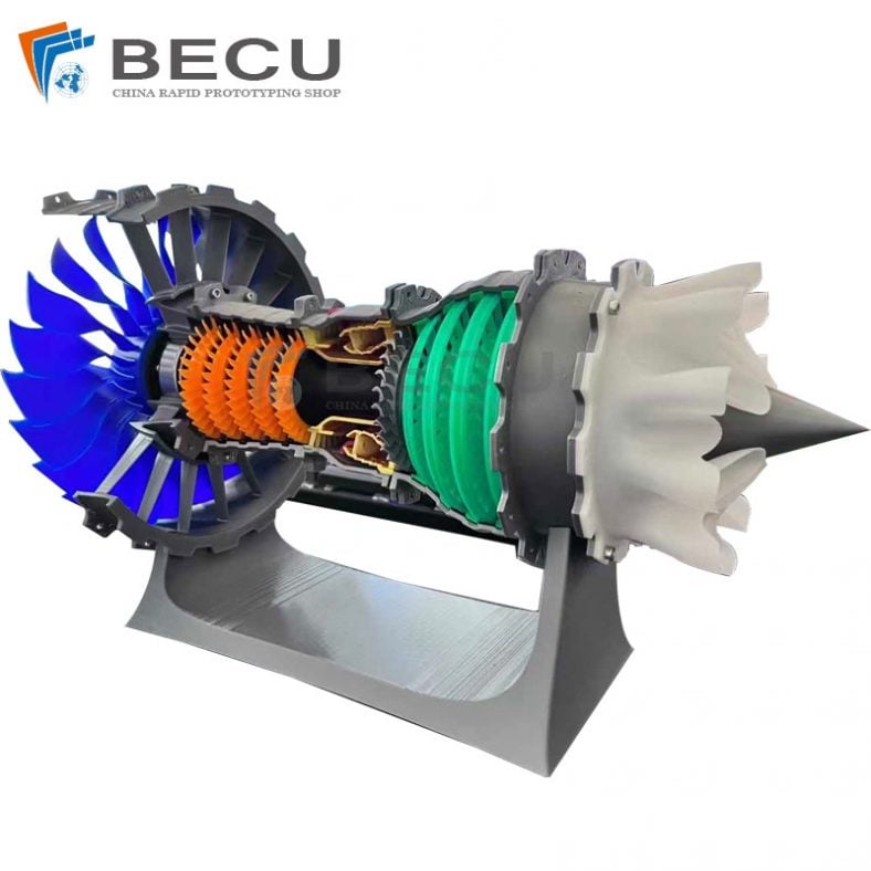
3D Printed Jet Engine Model
-

3D Printed Inconel Exhaust Manifold
-

3D Printed Black Myth: Wukong Model
-
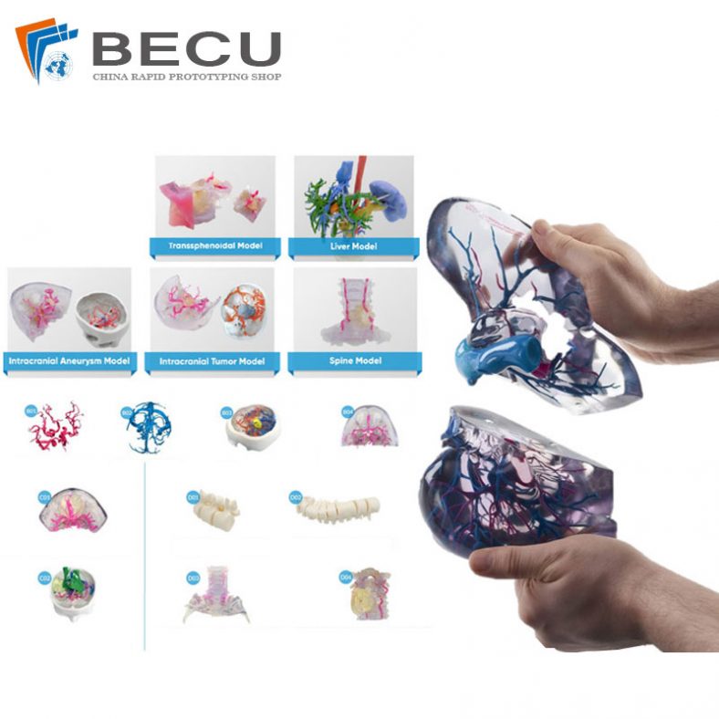
Omni-Directional Surgical Planning Medical Models
-
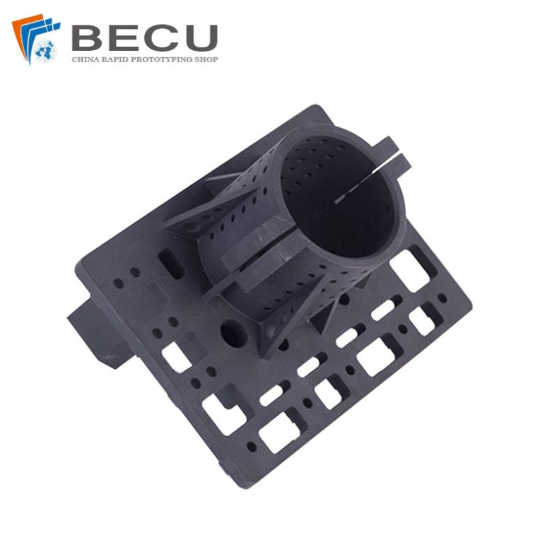
3D Printing Pool Pressure Cleaner Parts and Accessories
-
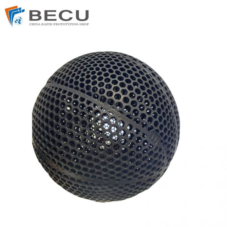
Nylon 3D Printed Size 5 Basketball
-
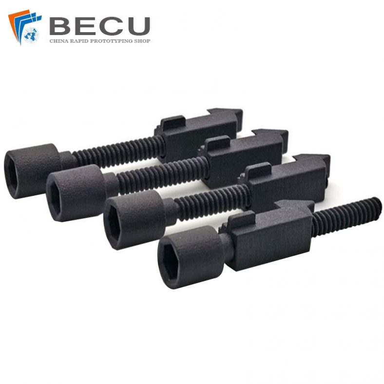
Black Nylon Medical Threaded Screw By MJF 3D Printing