
In the field of materials science and engineering, mechanical properties such as stiffness, strength, and elasticity are critical for understanding how materials behave under various types of loading conditions.
Among these properties, moduli—quantitative measures of a material’s stiffness—are fundamental in characterizing the deformation behavior of solids. Three commonly discussed moduli are the Flexural Modulus, Young’s Modulus, and Elastic Modulus. These terms are often used interchangeably in casual contexts, leading to confusion, yet they describe distinct aspects of material behavior under specific loading conditions.
The importance of these moduli cannot be overstated. They are essential in designing structures, selecting materials for engineering applications, and predicting how materials will respond to forces in real-world scenarios. For instance, Young’s Modulus is a cornerstone in the design of tensile structures, while Flexural Modulus is critical for components subjected to bending, such as beams or panels. Elastic Modulus, often a broader term, encompasses various moduli depending on the context. This article aims to clarify these concepts, dispel common misconceptions, and provide a detailed framework for understanding their interrelations, supported by theoretical derivations, experimental considerations, and practical examples.
Historical Context and Development
The concept of material stiffness has evolved over centuries, with contributions from scientists and engineers who sought to quantify how materials deform under external forces. The origins of Young’s Modulus can be traced to the early 19th century, named after Thomas Young, who described the relationship between stress and strain in tensile loading. Young’s work built upon earlier studies by Robert Hooke, who introduced the concept of elasticity with his famous law, Ut tensio, sic vis (“As the extension, so the force”). Flexural Modulus, while less explicitly named in early literature, emerged as engineers began analyzing bending behavior in beams, with contributions from Euler and Bernoulli in the 18th century. The term Elastic Modulus, as a general descriptor, gained prominence as materials science formalized in the 20th century, encompassing various stiffness measures under the umbrella of elastic deformation.
The development of standardized testing methods, such as those by the American Society for Testing and Materials (ASTM) and the International Organization for Standardization (ISO), further refined the measurement of these moduli. These standards ensured consistency in experimental protocols, enabling engineers to compare material properties across different contexts. Today, advancements in computational modeling and finite element analysis (FEA) have enhanced our ability to predict material behavior, relying heavily on accurate modulus values. Understanding the historical evolution of these concepts provides a foundation for appreciating their modern applications and the nuances that distinguish them.
Definitions and Fundamental Concepts
Young’s Modulus
Young’s Modulus, often denoted as E, is a measure of a material’s stiffness under uniaxial tensile or compressive loading. It is defined as the ratio of normal stress (force per unit area, σ) to normal strain (deformation per unit length, ε) within the linear elastic region of the material’s stress-strain curve. Mathematically, it is expressed as:
[ E = \frac{\sigma}{\varepsilon} ]
where:
- σ = Normal stress (Pa or N/m²)
- ε = Normal strain (dimensionless)
- E = Young’s Modulus (Pa or N/m²)
Young’s Modulus is a fundamental property of isotropic materials, such as metals and ceramics, and is typically measured using tensile testing machines that apply controlled forces to a specimen. The resulting stress-strain curve reveals the elastic region where Hooke’s Law applies, and Young’s Modulus is calculated from the slope of this linear portion. For anisotropic materials, such as composites or wood, Young’s Modulus may vary with direction, requiring multiple measurements along different axes.
Flexural Modulus
Flexural Modulus, sometimes referred to as the modulus of elasticity in bending, quantifies a material’s stiffness when subjected to bending or flexural loading. It is typically measured during a three-point or four-point bending test, where a beam-like specimen is loaded until it deforms. The Flexural Modulus is calculated based on the relationship between the applied load, the resulting deflection, and the geometry of the specimen. The formula for Flexural Modulus in a three-point bending test is derived from beam theory and is given by:
[ E_f = \frac{L^3 m}{4 b d^3} ]
where:
- E_f = Flexural Modulus (Pa or N/m²)
- L = Length of the support span (m)
- m = Slope of the load-deflection curve (N/m)
- b = Width of the specimen (m)
- d = Thickness of the specimen (m)
Flexural Modulus is particularly relevant for materials used in applications involving bending, such as structural beams, panels, or flexible components. Unlike Young’s Modulus, which assumes uniaxial loading, Flexural Modulus accounts for complex stress distributions, including tensile, compressive, and shear stresses, that occur during bending.
Elastic Modulus
The term Elastic Modulus is a general descriptor that refers to any modulus describing a material’s elastic behavior, including Young’s Modulus, Flexural Modulus, Shear Modulus, or Bulk Modulus, depending on the loading condition. In many contexts, Elastic Modulus is used synonymously with Young’s Modulus, particularly in introductory materials science texts. However, this usage can be misleading, as Elastic Modulus may also refer to other moduli in specific scenarios. For example:
- Shear Modulus (G): Measures stiffness under shear loading.
- Bulk Modulus (K): Measures resistance to uniform compression.
For clarity, this article uses Elastic Modulus as an umbrella term, with Young’s Modulus and Flexural Modulus as specific instances. The Elastic Modulus is always associated with the linear elastic region of deformation, where the material returns to its original shape upon unloading, adhering to Hooke’s Law.
Theoretical Relationships Between Moduli
The relationship between Flexural Modulus, Young’s Modulus, and Elastic Modulus depends on the material’s isotropy, microstructure, and testing conditions. For isotropic, homogeneous materials, Flexural Modulus and Young’s Modulus are theoretically equivalent, as both describe the material’s stiffness within the elastic regime. This equivalence arises because bending involves tensile and compressive stresses, which are governed by Young’s Modulus in an isotropic material. However, in practice, differences may emerge due to experimental factors or material anisotropy.

Isotropic Materials
For isotropic materials, the stress distribution in a bending test can be analyzed using classical beam theory. In a three-point bending test, the maximum tensile stress occurs at the bottom surface of the beam, and the maximum compressive stress occurs at the top. These stresses are directly related to Young’s Modulus, and the Flexural Modulus calculated from the test should, in theory, equal Young’s Modulus. The relationship can be expressed as:
[ E_f \approx E ]
However, deviations may occur due to:
- Shear Deformation: In short beams, shear stresses contribute significantly to deflection, reducing the apparent Flexural Modulus.
- Surface Imperfections: Microcracks or surface irregularities can affect bending behavior more than tensile behavior.
- Testing Artifacts: Misalignment, friction, or non-ideal loading conditions can introduce errors.
Anisotropic Materials
For anisotropic materials, such as fiber-reinforced composites or wood, the Flexural Modulus and Young’s Modulus may differ significantly. Anisotropy arises when material properties vary with direction, often due to aligned fibers, grains, or layered structures. In such cases, Young’s Modulus is measured along a specific axis (e.g., the fiber direction), while Flexural Modulus reflects a composite response to bending, which involves stresses in multiple directions. The relationship can be complex and is often described using constitutive models, such as those based on laminate theory for composites.
For example, in a unidirectional composite, the Flexural Modulus may be influenced by:
- Fiber Orientation: Fibers aligned parallel to the beam axis contribute to higher stiffness.
- Matrix Properties: The polymer matrix may dominate shear behavior, affecting deflection.
- Interlaminar Effects: Delamination or weak interlayer bonding can reduce Flexural Modulus.
Conversion Between Moduli
Converting between Flexural Modulus and Young’s Modulus is not always straightforward, especially for anisotropic materials. For isotropic materials, the two moduli are approximately equal, and no conversion is needed. However, for anisotropic materials or when experimental differences arise, empirical correlations or theoretical models may be used. One approach is to use finite element analysis (FEA) to simulate bending and tensile tests, calibrating the model to match experimental data.
In some cases, correction factors are applied to account for shear deformation in bending tests. For example, Timoshenko beam theory modifies the deflection equation to include shear effects:
[ \delta = \frac{PL^3}{48EI} + \frac{PL}{4GA} ]
where:
- δ = Deflection (m)
- P = Applied load (N)
- L = Span length (m)
- E = Young’s Modulus (Pa)
- I = Moment of inertia (m⁴)
- G = Shear Modulus (Pa)
- A = Cross-sectional area (m²)
By comparing the measured Flexural Modulus to the theoretical Young’s Modulus, engineers can estimate the contribution of shear deformation and adjust accordingly.
Experimental Measurement Techniques
Measuring Young’s Modulus
Young’s Modulus is typically measured using a tensile test, as specified by standards such as ASTM E8 (for metals) or ASTM D638 (for plastics). The procedure involves:
- Preparing a dog-bone-shaped specimen with a known cross-sectional area.
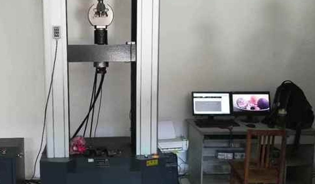
- Mounting the specimen in a universal testing machine.
- Applying a gradually increasing tensile load while measuring force and elongation.
- Calculating stress (force/area) and strain (elongation/original length).
- Determining the slope of the linear portion of the stress-strain curve.
Advanced techniques, such as digital image correlation (DIC) or extensometers, improve the accuracy of strain measurements. For brittle materials, compressive tests (e.g., ASTM C773) may be used instead, as tensile failure occurs too rapidly.
Measuring Flexural Modulus
Flexural Modulus is measured using bending tests, with three-point and four-point configurations being the most common. ASTM D790 and ISO 178 provide guidelines for plastics, while ASTM C78 applies to concrete. The steps include:
- Preparing a rectangular or beam-shaped specimen.
- Placing the specimen on supports (for three-point bending) or loading points (for four-point bending).
- Applying a load at a constant rate and measuring deflection.
- Calculating the Flexural Modulus using the load-deflection curve and specimen geometry.
Four-point bending is often preferred for brittle materials, as it produces a uniform stress distribution between the loading points, reducing the risk of premature failure.
Challenges in Measurement
Both tensile and bending tests face challenges that can affect modulus measurements:
- Specimen Preparation: Imperfections, such as voids or uneven surfaces, can skew results.
- Alignment: Misalignment in the testing machine can introduce errors.
- Rate Dependence: Viscoelastic materials, like polymers, exhibit modulus variations with loading rate.
- Environmental Factors: Temperature, humidity, or chemical exposure can alter material properties.
To mitigate these issues, standardized protocols emphasize precise specimen preparation, controlled testing conditions, and statistical analysis of multiple samples.
Comparison of Moduli Across Material Classes
The values of Young’s Modulus and Flexural Modulus vary widely across material classes, reflecting differences in microstructure, bonding, and composition. The following table summarizes typical modulus values for common materials, highlighting similarities and differences.
| Material | Young’s Modulus (GPa) | Flexural Modulus (GPa) | Notes |
|---|---|---|---|
| Steel (Mild) | 200–210 | 200–210 | Isotropic, moduli are nearly identical due to homogeneity. |
| Aluminum | 68–72 | 68–72 | Isotropic, similar moduli, but surface effects may cause slight deviations. |
| Polyethylene (HDPE) | 0.8–1.2 | 0.7–1.1 | Viscoelastic, Flexural Modulus may be lower due to shear deformation. |
| Glass | 50–90 | 50–90 | Brittle, moduli are equivalent but sensitive to surface flaws. |
| Carbon Fiber Composite | 50–400 (directional) | 30–300 (directional) | Anisotropic, moduli vary with fiber orientation and matrix properties. |
| Wood (Oak, along grain) | 11–14 | 10–13 | Anisotropic, Flexural Modulus lower due to shear and defects. |
| Concrete | 20–40 | 15–35 | Heterogeneous, Flexural Modulus reduced by microcracks and aggregates. |
Metals
Metals, such as steel and aluminum, are typically isotropic and exhibit nearly identical Young’s and Flexural Moduli. Their high stiffness arises from strong metallic bonds, and their homogeneity ensures consistent behavior under tensile and bending loads. However, alloy composition, heat treatment, and manufacturing processes (e.g., rolling or forging) can introduce slight anisotropy, affecting modulus measurements.
Polymers
Polymers, including thermoplastics and thermosets, are often viscoelastic, meaning their moduli depend on loading rate and temperature. Flexural Modulus is typically lower than Young’s Modulus due to shear deformation in bending tests, especially for short specimens. Additives, such as fillers or reinforcements, can significantly alter modulus values, making polymers a diverse class for modulus comparisons.
Composites
Fiber-reinforced composites, such as carbon fiber or glass fiber laminates, are highly anisotropic, with moduli varying by orders of magnitude depending on fiber orientation. Young’s Modulus is highest along the fiber direction, while Flexural Modulus reflects a combination of fiber and matrix properties. The design of composite structures often involves tailoring the layup to optimize both moduli for specific loading conditions.
Ceramics and Brittle Materials
Ceramics, such as glass or alumina, are brittle and exhibit high moduli due to strong ionic or covalent bonds. Their Young’s and Flexural Moduli are theoretically equivalent, but experimental values may differ due to surface flaws or microcracks, which are more pronounced in bending tests. Careful specimen preparation is critical for accurate measurements.
Natural Materials
Natural materials, such as wood or bone, are anisotropic and heterogeneous, leading to differences between Young’s and Flexural Moduli. For example, wood’s Flexural Modulus is often lower than its Young’s Modulus along the grain due to shear effects and defects like knots. Bone, a composite of collagen and hydroxyapatite, exhibits similar trends, with moduli varying by anatomical location.
Applications in Engineering and Design
Structural Engineering
In structural engineering, Young’s Modulus is critical for designing components subjected to tensile or compressive loads, such as columns, cables, or trusses. Flexural Modulus is equally important for beams, slabs, or bridges, where bending is the dominant mode of deformation. For example, in reinforced concrete design, the Flexural Modulus of concrete influences the deflection of beams, while the Young’s Modulus of steel reinforcement governs tensile strength.
Aerospace and Automotive
Aerospace and automotive industries rely on materials with high stiffness-to-weight ratios, such as aluminum alloys and carbon fiber composites. Young’s Modulus is used to predict the behavior of fuselage skins or chassis components under tensile loads, while Flexural Modulus informs the design of wings, spoilers, or panels subjected to aerodynamic forces. The anisotropy of composites requires careful consideration of both moduli during material selection.
Biomedical Engineering
In biomedical applications, moduli are crucial for designing implants and prosthetics. For instance, the Young’s Modulus of titanium alloys (≈110 GPa) is chosen for bone implants to match the stiffness of cortical bone (≈20 GPa), minimizing stress shielding. Flexural Modulus is relevant for dental restorations or orthopedic plates, which experience bending during chewing or movement.
Consumer Products
Consumer products, such as furniture, packaging, or electronics, often involve polymers and composites, where Flexural Modulus is a key design parameter. For example, the stiffness of a plastic chair is determined by its Flexural Modulus, ensuring it can support weight without excessive deflection. Young’s Modulus is less relevant unless the product experiences significant tensile loads.
Advanced Topics and Research Frontiers
Nonlinear Elasticity and Modulus Variation
While Young’s and Flexural Moduli are defined within the linear elastic regime, many materials exhibit nonlinear behavior at higher strains. Research into nonlinear elasticity explores how moduli vary with strain, temperature, or loading rate, particularly for polymers and biological tissues. Techniques like nanoindentation and dynamic mechanical analysis (DMA) provide insights into modulus variations at small scales or under cyclic loading.
Modulus in Nanomaterials
Nanomaterials, such as graphene or carbon nanotubes, exhibit extraordinarily high moduli due to their atomic-scale structures. Measuring Young’s Modulus at the nanoscale requires specialized techniques, such as atomic force microscopy (AFM) or molecular dynamics simulations. Flexural Modulus is less commonly studied but is relevant for applications like flexible electronics or nanobeams.
Computational Modeling
Finite element analysis (FEA) and other computational tools have revolutionized modulus prediction and material design. By simulating tensile and bending tests, engineers can estimate Young’s and Flexural Moduli for complex geometries or composite structures. Machine learning is also emerging as a tool for predicting moduli based on material composition and microstructure, reducing the need for extensive experimental testing.
Environmental and Time-Dependent Effects
Environmental factors, such as moisture, temperature, or radiation, can alter moduli over time. For example, polymers may experience creep or relaxation, reducing their effective modulus under sustained loading. Research into durability and aging focuses on how moduli evolve in harsh environments, informing the design of long-lasting structures.
Practical Conversion and Calibration
In engineering practice, converting between Flexural Modulus and Young’s Modulus may be necessary when data from one test is unavailable. For isotropic materials, the conversion is straightforward, as the moduli are approximately equal. For anisotropic materials, empirical relationships or computational models are used. A common approach is to conduct both tensile and bending tests on the same material and establish a correlation factor, such as:
[ E_f = k \cdot E ]
where k is a material-specific constant determined experimentally. For composites, laminate theory or micromechanical models provide theoretical conversions based on fiber and matrix properties.
Calibration is also critical when comparing moduli across different testing standards. For example, ASTM and ISO standards may use slightly different specimen geometries or loading rates, affecting modulus values. Engineers must account for these differences when integrating data from multiple sources.
Conclusion
The distinctions between Flexural Modulus, Young’s Modulus, and Elastic Modulus are rooted in their definitions, measurement methods, and applications. Young’s Modulus describes stiffness under uniaxial loading, Flexural Modulus quantifies resistance to bending, and Elastic Modulus serves as a general term encompassing various stiffness measures. For isotropic materials, the moduli are often equivalent, but differences arise in anisotropic or heterogeneous materials due to complex stress distributions and experimental factors.
Understanding these moduli is essential for materials selection, structural design, and performance prediction across industries. Advances in testing, modeling, and material science continue to refine our knowledge, enabling engineers to design innovative solutions with greater precision. By clarifying the relationships and conversions between these moduli, this article provides a comprehensive resource for researchers, students, and professionals in materials science and engineering.
The Detail Of BE-CU Sheet Metal Company
BE-CU is a professional and technical enterprise engaged in sheet metal fabrication, with over 2000 m2 sheet metal workshop and has one-stop service of industrial automation R&D, production, processing and sales.Custom manufacturer of sheet metal component assemblies made from stainless steel, aluminum and carbon steel. Offered in different specifications and features.Markets served include aerospace, lighting, medical, defense, semiconductor/electronics, capacitor, chemical processing and energy.Capable of maintaining dimensional tolerance up to +/-0.005 in. Capabilities include contract manufacturing, fabrication, machining, bending, milling, cutting, forming, drilling, fitting, assembly, notching, punching, rolling, turning, CNC press braking, flame and high definition plasma cutting, saw cutting, shearing, prototyping, high volume, short run and long run production and MIG, TIG and arc welding. Secondary services include Blanchard grinding, galvanizing and painting.
-
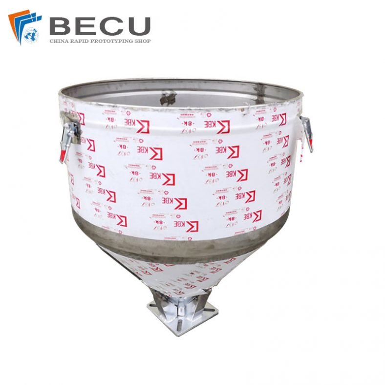
Sheet Metal Fabrication Injection Molding Machine Hopper
-
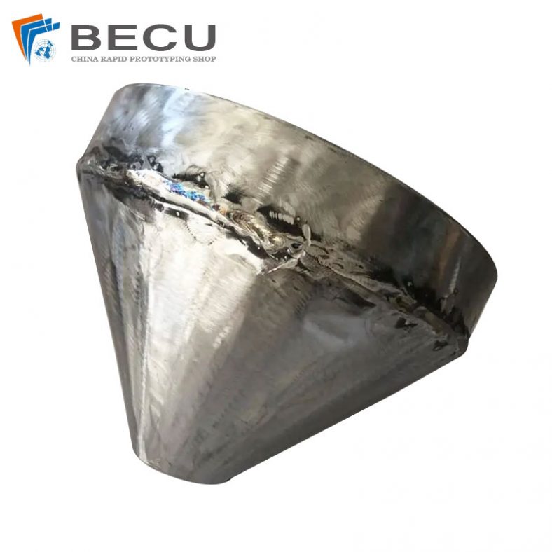
Sheet Metal Fabrication Funnel For Agricultural Machinery
-

Sheet Metal Fabrication Galvanized Spiral Air Duct
-

PCS Fan Ductwork Sheet Metal Housing
-

Custom Sheet Metal Surgical Instrument Sterilization Box For Beauty Salon
-

Precision Fabrication Green Energy EV Charging Station Cabinet
-
TA1TA2 Alloy Sheet Metal Manufacturing Machinery Support Parts
-

Sheet Metal Fabrication Aluminum 5052 Medical Box For Fire Fighting