
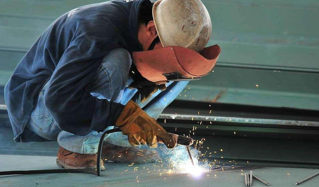
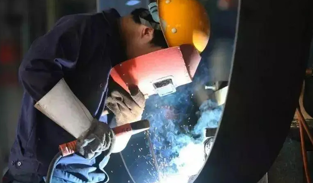
Welding is a versatile and crucial skill in various industries, from construction to automotive manufacturing. With numerous welding methods available, each designed for specific applications and materials, understanding the basics of each technique is essential for both beginners and experienced welders. In this comprehensive guide, we will explore 17 common welding methods, providing in-depth insights into their processes, applications, advantages, and limitations.
Manual Arc Welding
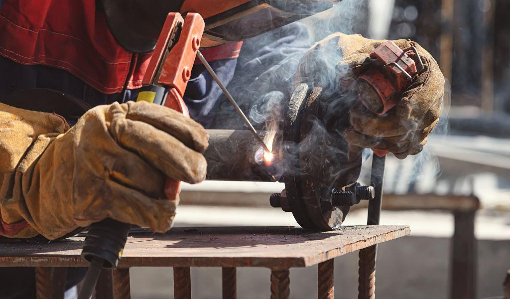
Here’s an overview of the manual arc welding process:
Equipment:
- Power Source: A welding machine that provides the necessary electrical current for welding.
- Electrode Holder: A device that holds and connects the electrode to the welding machine.
- Welding Electrodes: Consumable rods with a metal core and flux coating that melts to form a protective gas shield and slag during the welding process.
- Protective Gear: Welders should wear appropriate personal protective equipment, including a welding helmet with a darkened shield, welding gloves, flame-resistant clothing, and safety glasses.
Process:
- Setup: Clean the workpiece to remove any dirt, rust, or contaminants. Proper preparation ensures a strong and clean weld.
- Select Electrode: Choose the appropriate welding electrode based on the type of metal being welded and the welding conditions.
- Adjust Current: Set the welding machine to the recommended current based on the electrode size and type.
- Strike an Arc: Hold the electrode holder at a slight angle and strike the electrode against the workpiece to create an electric arc. Maintain a steady arc length.
- Welding Technique: Move the electrode along the joint in a controlled manner, creating a weld bead. The molten metal from the electrode fuses with the base metal to form a solid joint.
- Filler Metal: If necessary, use a weaving or oscillating motion to ensure proper penetration and fusion. Add filler metal as needed to build up the weld.
- Cooling: Allow the weld to cool gradually to prevent stress and cracking. Avoid rapid cooling methods that can lead to brittle welds.
Advantages:
- Versatility: Can be used for various materials and thicknesses.
- Portability: Manual arc welding equipment is relatively portable and can be used in different locations.
- Cost-Effective: Equipment and consumables are often more affordable compared to other welding processes.
Disadvantages:
- Slag Removal: Requires post-weld cleanup to remove the slag produced during the welding process.
- Skill Dependence: Achieving high-quality welds requires skill and experience.
- Limited Joint Accessibility: The size and shape of the electrode and holder can limit access to certain joint configurations.
Proper training and practice are crucial for achieving successful manual arc welds. Additionally, understanding the specific requirements of the welding project and materials is essential for producing strong and reliable welds.
Tungsten Inert Gas (TIG) Welding
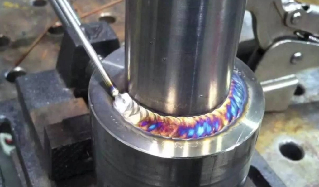
Here’s an overview of the TIG welding process:
Equipment:
- Power Source: TIG welding requires a constant current power supply, typically DC for most materials or AC for aluminum.
- Tungsten Electrode: A non-consumable tungsten electrode is used to create the electric arc. It remains intact during the welding process.
- Torch: The TIG welding torch holds and directs the tungsten electrode and provides a shielding gas to protect the weld area.
- Shielding Gas: An inert gas, such as argon or helium, is used to shield the molten weld pool from atmospheric contamination.
- Filler Rod: Depending on the application, a filler rod made of the same or compatible material may be used to add material to the weld.
Process:
- Setup: Clean the workpiece thoroughly to remove any contaminants. Proper surface preparation is crucial for TIG welding.
- Select Tungsten Electrode: Choose a tungsten electrode type based on the material being welded. Thoriated, ceriated, lanthanated, and pure tungsten electrodes are common options.
- Insert Tungsten Electrode: Insert the tungsten electrode into the TIG torch and secure it in place.
- Set Polarity and Current: TIG welding can use DC (direct current) for most materials or AC (alternating current) for aluminum. Adjust the welding machine settings to the appropriate polarity and current.
- Gas Flow: Adjust the flow of shielding gas to create an inert atmosphere around the welding arc, preventing oxidation and contamination.
- Arc Initiation: Use a high-frequency start or lift-arc method to initiate the electric arc between the tungsten electrode and the workpiece.
- Welding Technique: Move the torch along the joint, maintaining a consistent arc length and directing the shielding gas to protect the weld pool. The non-consumable tungsten electrode does not melt; instead, it transfers its heat to the workpiece.
- Filler Metal (if needed): If additional material is required, a filler rod can be added to the weld pool manually.
- Cooling: Allow the welded area to cool gradually to minimize stress and avoid cracking.
Advantages:
- Precision: TIG welding allows for precise control over the welding process, making it suitable for thin materials and intricate welds.
- Clean Welds: Produces high-quality, clean welds with minimal spatter.
- Versatility: Can be used on a wide range of materials, including stainless steel, aluminum, titanium, and more.
Disadvantages:
- Slower Process: TIG welding is generally slower than some other welding processes.
- Skill Requirement: Requires a high level of skill and experience to achieve optimal results.
- Limited Joint Access: Access to the joint can be challenging in certain configurations.
TIG welding is commonly used in applications where high-quality, precise welds are necessary, such as aerospace, automotive, and nuclear industries.
Gas Metal Arc Welding (GMAW)
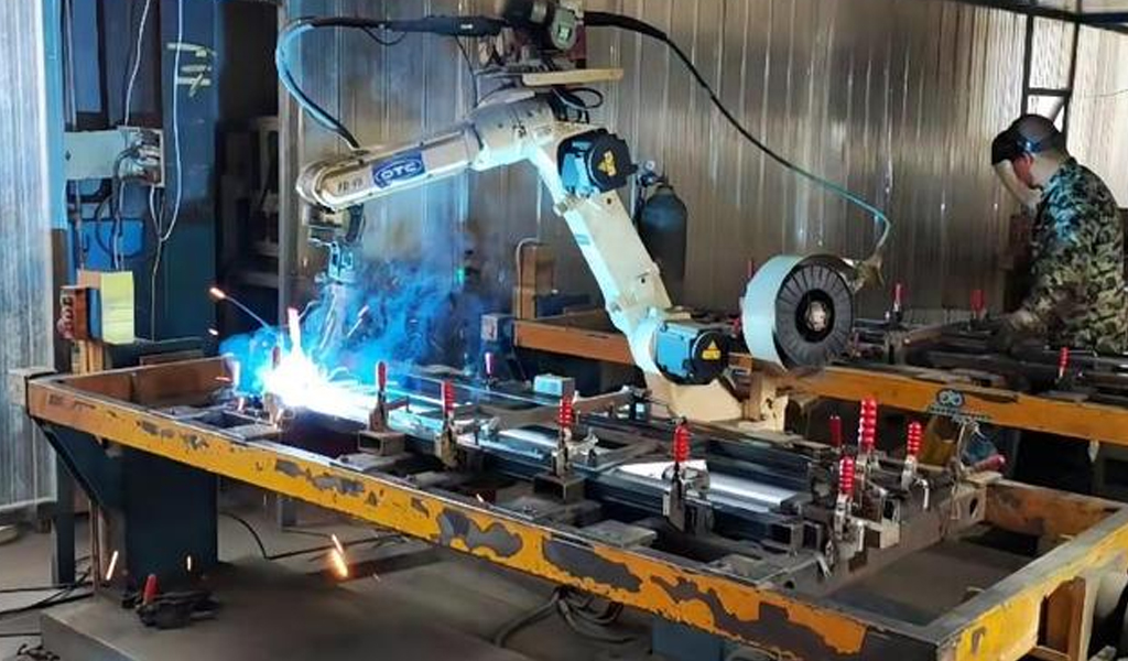
Here’s an overview of the GMAW welding process:
Equipment:
- Power Source: GMAW requires a constant voltage power supply, often provided by a welding machine.
- Wire Feeder: A motorized device that feeds the consumable electrode wire through the welding torch and into the weld pool.
- Welding Gun or Torch: The welding gun or torch directs the electrode wire to the workpiece and releases the shielding gas.
- Consumable Electrode Wire: A spool of solid or flux-cored wire is used as the consumable electrode. The wire is continuously fed into the welding arc.
- Shielding Gas: An inert gas (such as argon, helium, or a mixture) is used to shield the molten weld pool from atmospheric contamination.
Process:
- Setup: Clean the workpiece to remove any contaminants and ensure proper joint fit-up.
- Select Electrode and Gas: Choose the appropriate electrode wire and shielding gas based on the material being welded and the welding conditions.
- Insert Electrode: Load the spool of consumable electrode wire into the wire feeder and secure it.
- Set Voltage and Wire Feed Speed: Adjust the welding machine settings for the appropriate voltage and wire feed speed based on the material thickness and type.
- Gas Flow: Adjust the flow of shielding gas to create an inert atmosphere around the welding arc, preventing oxidation and contamination.
- Arc Initiation: Activate the welding machine to initiate the electric arc between the consumable electrode wire and the workpiece.
- Welding Technique: Move the welding torch along the joint, keeping a consistent arc length. The consumable electrode wire melts and forms the molten weld pool as it is deposited onto the workpiece.
- Filler Metal (if needed): The consumable electrode wire serves as the filler metal, and additional filler metal may be added manually if required.
- Cooling: Allow the welded area to cool gradually to prevent stress and avoid cracking.
Advantages:
- High Deposition Rates: GMAW allows for high welding speeds and deposition rates.
- Versatility: Suitable for a wide range of materials and thicknesses.
- Minimal Cleanup: Generally produces clean welds with minimal spatter.
Disadvantages:
- Wind Sensitivity: Wind can affect the shielding gas, leading to potential weld quality issues.
- Skill Requirement: While GMAW is relatively easier to learn than some other processes, achieving high-quality welds still requires skill and experience.
- Limited Joint Access: Access to the joint can be limited in certain configurations.
GMAW is widely used in industries such as automotive, construction, and manufacturing, where high productivity and efficiency are essential. The process is effective for both thin and thick materials and is suitable for welding a variety of metals, including carbon steel, stainless steel, and aluminum.
Plasma Arc Welding
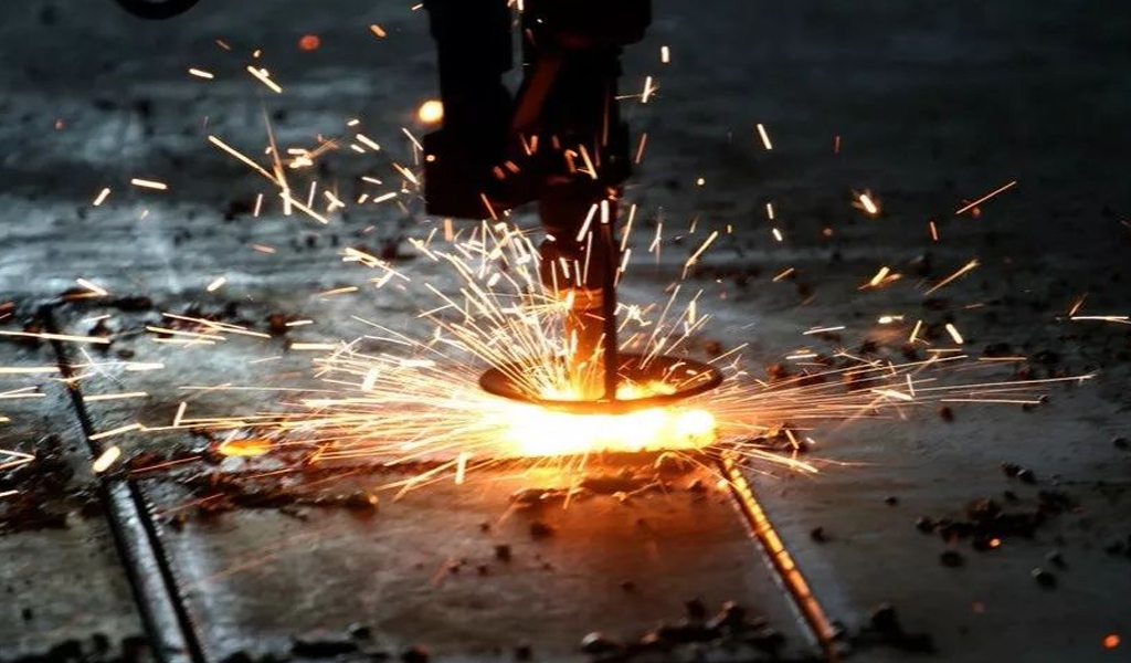
Here’s an overview of the Plasma Arc Welding process:
Equipment:
- Power Source: Provides the necessary electrical energy to create and sustain the plasma arc.
- Plasma Torch: The plasma torch consists of a tungsten electrode, a constricting nozzle, and a secondary shielding gas nozzle. The torch is designed to generate and control the plasma arc.
- Plasma Gas: Typically, an inert gas such as argon or a mixture of gases is used to create the plasma arc. This gas is fed through the torch and becomes ionized to form the plasma.
- Shielding Gas: An additional shielding gas, often argon, surrounds the plasma arc to protect the weld pool from atmospheric contamination.
- Workpiece: The metals being joined are prepared and positioned for welding.
Process:
- Setup: Clean the workpiece to remove any contaminants and ensure proper joint fit-up.
- Select Plasma Gas: Choose the appropriate plasma gas based on the material being welded.
- Gas Flow: Adjust the flow of plasma gas and shielding gas to create and maintain the plasma arc and protect the weld pool.
- Arc Initiation: Use a high-frequency start or other methods to initiate the plasma arc between the tungsten electrode and the workpiece.
- Welding Technique: Move the plasma torch along the joint, maintaining a consistent arc length. The extremely high temperature of the plasma arc results in efficient and precise welding.
- Filler Metal (if needed): If additional material is required, a filler rod can be manually added to the weld pool.
- Cooling: Allow the welded area to cool gradually to prevent stress and avoid cracking.
Advantages:
- High Energy Density: Plasma arc welding produces a highly concentrated and high-temperature arc, allowing for deep penetration and high welding speeds.
- Precision: Provides excellent control over the welding process, making it suitable for thin materials and intricate welds.
- Versatility: Can be used for a variety of materials, including stainless steel, aluminum, copper, and other alloys.
Disadvantages:
- Equipment Cost: Plasma arc welding equipment can be more expensive than some other welding processes.
- Skill Requirement: Achieving optimal results requires skill and experience.
- Limited Joint Accessibility: Access to the joint can be challenging in certain configurations.
Plasma arc welding is commonly used in applications where high precision, deep penetration, and high welding speeds are essential, such as in aerospace, automotive, and electronic industries. The process is particularly well-suited for welding thin materials and conducting precision welding tasks.
Tubular Wire Arc Welding
Here’s an overview of the Tubular Wire Arc Welding process:
Equipment:
- Power Source: Provides the necessary electrical energy for the welding process.
- Wire Feeder: A motorized device that feeds the tubular electrode wire through the welding torch.
- Welding Gun or Torch: The welding gun directs the electrode wire to the workpiece.
- Tubular Electrode Wire: The electrode is a hollow tube filled with flux. It can be either gas-shielded or self-shielded, depending on the application.
- Shielding Gas (optional): In gas-shielded FCAW, an external shielding gas may be used to protect the weld from atmospheric contamination.
Process:
- Setup: Clean the workpiece to remove contaminants and ensure proper joint fit-up.
- Select Electrode: Choose the appropriate tubular electrode based on the material being welded and the welding conditions. Gas-shielded or self-shielded electrodes can be used.
- Insert Electrode: Load the spool of tubular electrode wire into the wire feeder and secure it.
- Set Voltage and Wire Feed Speed: Adjust the welding machine settings for the appropriate voltage and wire feed speed based on the material thickness and type.
- Gas Flow (if used): In gas-shielded FCAW, adjust the flow of shielding gas to create an inert atmosphere around the welding arc.
- Arc Initiation: Activate the welding machine to initiate the electric arc between the tubular electrode and the workpiece.
- Welding Technique: Move the welding torch along the joint, keeping a consistent arc length. The flux within the electrode generates a protective gas shield, and the melted flux forms a slag that covers the weld pool, preventing atmospheric contamination.
- Filler Metal (if needed): The tubular electrode wire serves as the filler metal. Additional filler metal may be added manually if required.
- Cooling: Allow the welded area to cool gradually to prevent stress and avoid cracking.
Advantages:
- High Deposition Rates: FCAW allows for high welding speeds and deposition rates, making it suitable for fast production.
- Versatility: Can be used on a wide range of materials and thicknesses.
- All-Position Welding: FCAW is well-suited for all-position welding, including vertical and overhead.
Disadvantages:
- Equipment Sensitivity: Wind can affect the shielding gas, leading to potential weld quality issues in gas-shielded FCAW.
- Slag Removal: Post-weld cleanup is necessary to remove the slag produced during the welding process.
- Skill Requirement: While FCAW is relatively easier to learn than some other processes, achieving high-quality welds still requires skill and experience.
Tubular Wire Arc Welding is commonly used in construction, shipbuilding, and other heavy fabrication industries due to its high productivity and versatility. The process is effective for both mild and low-alloy steels.
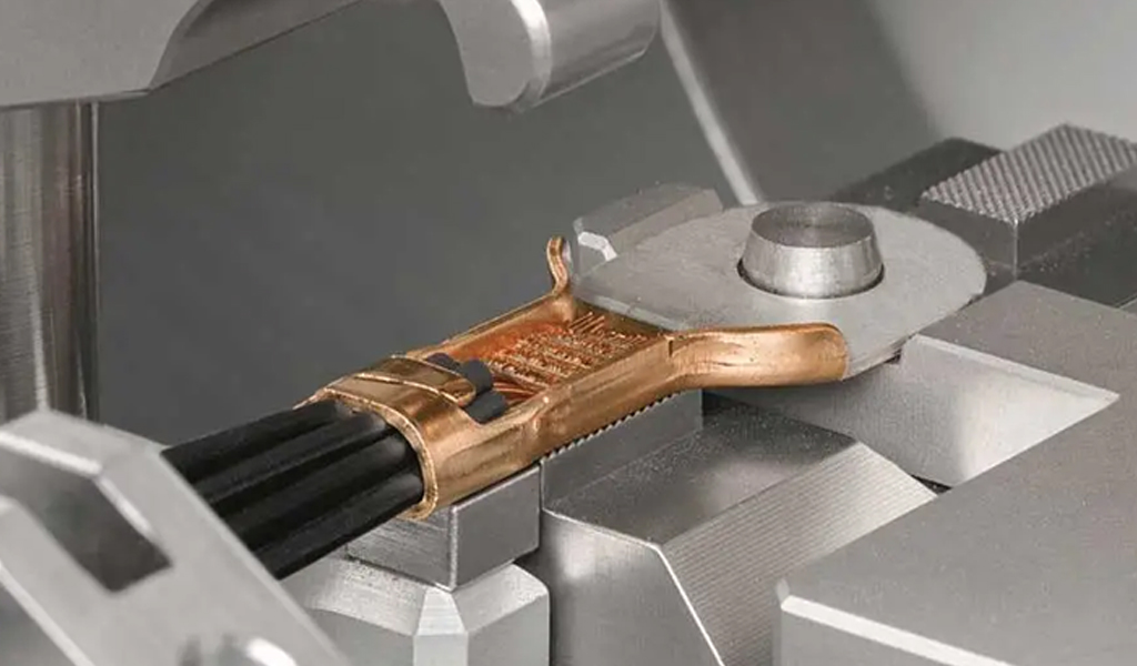
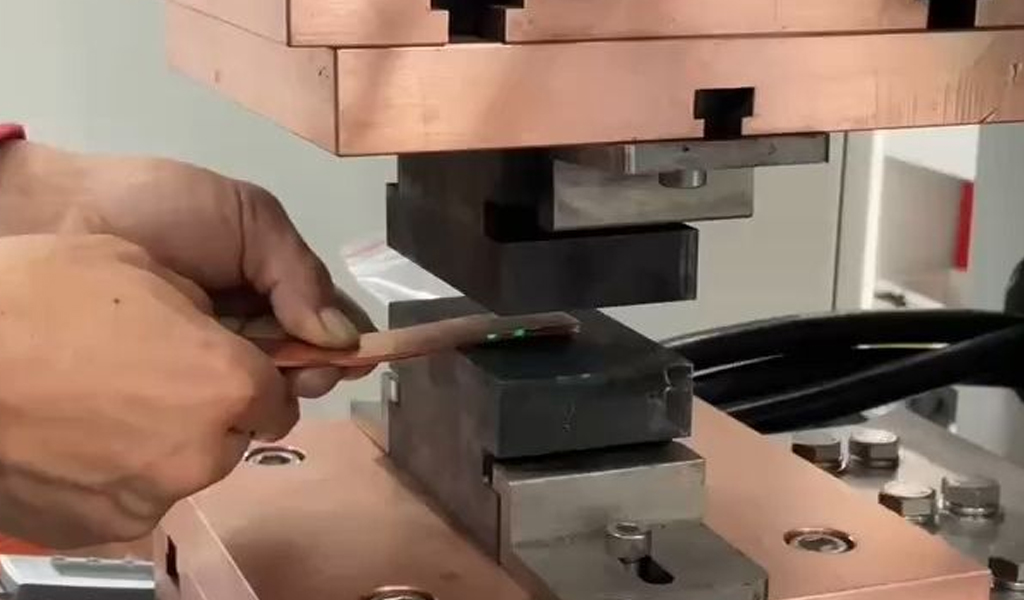
Resistance Welding
Here’s an overview of the general resistance welding process:
Basic Equipment:
- Power Source: Provides the electric current required for resistance heating.
- Electrodes: Two copper or copper-alloy electrodes that apply pressure to the workpieces and conduct the electric current through them.
- Workpieces: The metal pieces to be joined are placed between the electrodes.
Process:
- Setup: Clean the surfaces of the workpieces to ensure good electrical contact and proper joint fit-up.
- Clamping: The workpieces are clamped between the electrodes, applying pressure to ensure good contact.
- Electric Current Flow: The power source applies an electric current through the workpieces, and the resistance to this current generates heat at the interface between the workpieces.
- Melting and Welding: As the workpieces heat up, they reach a temperature where the metal softens and melts at the contact point, forming a molten pool. Pressure from the electrodes consolidates the material, creating a weld.
- Cooling: The welded area is allowed to cool and solidify, forming a strong joint.
Types of Resistance Welding:
- Spot Welding: Used for joining overlapping sheets or plates at discrete points, such as in the automotive industry for assembling sheet metal components.
- Seam Welding: Similar to spot welding but produces a continuous weld along the joint. It’s often used for welding cylindrical or tubular components.
- Projection Welding: Involves the use of specially designed electrodes to concentrate the current and heat in specific areas, creating projections or embossed features on one of the workpieces.
- Flash Welding: Utilizes a flashing process where the workpieces are rapidly heated and then joined under pressure. It is commonly used for joining bars or cylindrical sections.
Advantages:
- High Speed: Resistance welding processes are generally fast, making them suitable for high-volume production.
- Minimal Filler Material: Often requires no additional filler material.
- Clean Process: Produces clean welds without the need for flux or shielding gas.
Disadvantages:
- Limited Joint Designs: The joint configurations are somewhat restricted compared to other welding processes.
- Material Limitations: More suitable for certain materials, such as carbon steels and low-alloy steels.
Resistance welding is widely used in the automotive, aerospace, and electronics industries, among others, where high-speed and efficient production are essential. The process is favored for its ability to produce strong, consistent welds with minimal heat-affected zones.
Electron Beam Welding
Here’s an overview of the Electron Beam Welding process:
Basic Equipment:
- Electron Gun: Emits a stream of high-energy electrons.
- Electron Beam Column: Focuses and directs the electron beam onto the workpiece.
- Workpiece: The metals to be joined are positioned in the vacuum chamber.
- Electron Beam Deflection System (optional): Allows for the movement and control of the electron beam on the workpiece.
Process:
- Vacuum Chamber: The workpieces are placed in a vacuum chamber to eliminate the presence of air, which could interfere with the electron beam.
- Electron Gun Activation: The electron gun generates a high-speed stream of electrons.
- Electron Focusing: Magnetic lenses focus and concentrate the electron beam onto a small spot on the workpiece.
- Welding: The concentrated electron beam heats the workpiece, causing rapid melting and formation of a molten pool.
- Joint Formation: The molten pool solidifies to create a weld joint as the electron beam progresses along the joint line.
- Cooling: The welded area is allowed to cool gradually, and the vacuum chamber prevents oxidation of the molten metal.
Advantages:
- High Precision: Electron beam welding allows for precise control and high accuracy, making it suitable for welding small and intricate components.
- Deep Penetration: The focused electron beam can penetrate deep into the workpiece, resulting in strong welds even in thick materials.
- Minimal Distortion: The concentrated heat input minimizes the heat-affected zone, reducing distortion and preserving material properties.
Disadvantages:
- Vacuum Requirement: The process must be performed in a vacuum, making it more complex and expensive.
- Limited Joint Access: The workpieces must fit within the vacuum chamber, limiting joint access in certain applications.
- Specialized Equipment: Electron beam welding machines are specialized and can be costly to set up.
Applications:
- Electron beam welding is commonly used in aerospace and automotive industries for joining components made of high-strength materials.
- It is suitable for applications requiring high precision, such as in the production of medical devices and electronics.
- Electron beam welding is employed for joining dissimilar metals and welding refractory materials.
Despite its limitations, electron beam welding is a powerful tool in industries that require precise, high-quality welds, and it offers unique advantages in certain applications.
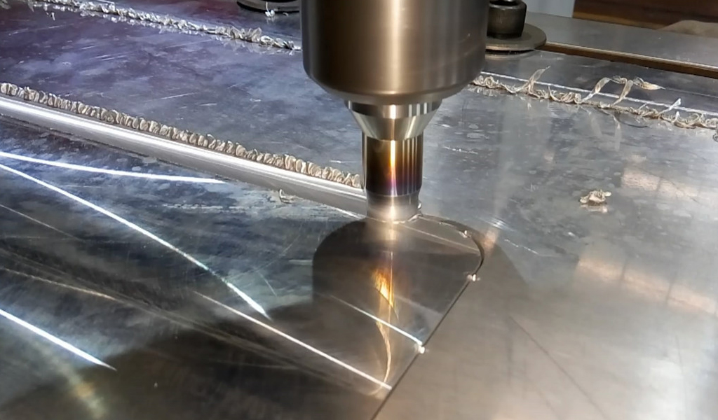
Laser Welding
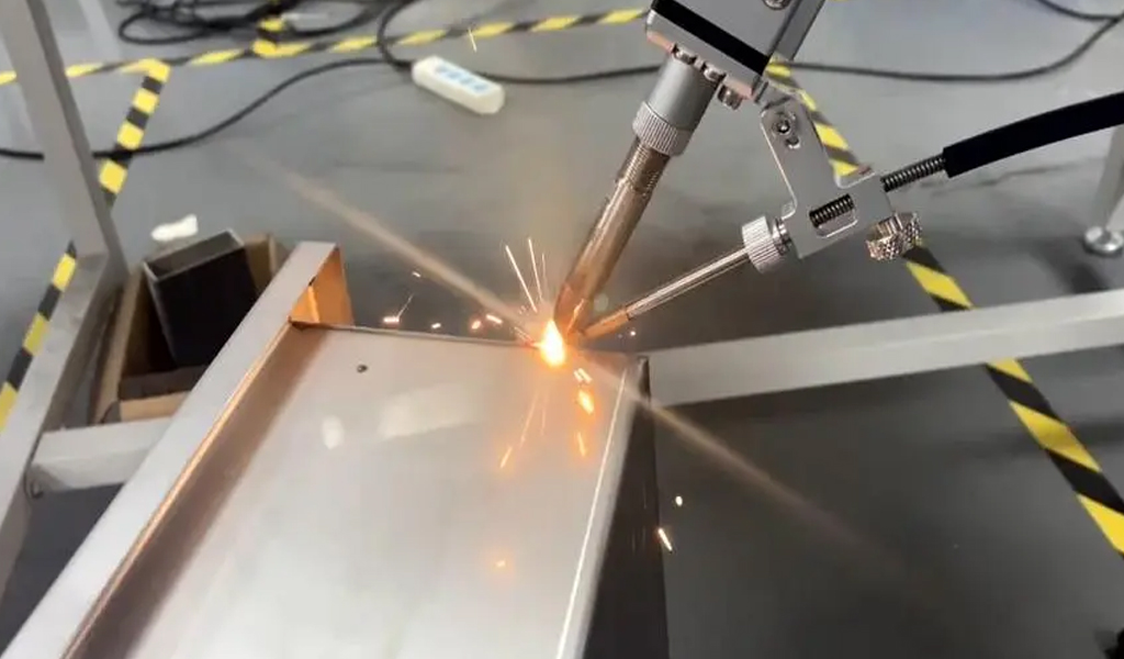
Here’s an overview of the laser welding process:
Basic Equipment:
- Laser Source: Emits a high-powered, focused laser beam.
- Focusing Optics: Direct and focus the laser beam onto the workpiece.
- Workpiece: The materials to be welded are positioned and prepared for welding.
- Motion System: Positions the laser beam and/or the workpiece for welding.
Process:
- Setup: Clean the workpieces to remove any contaminants and ensure proper joint fit-up.
- Laser Activation: The laser source emits a high-energy laser beam.
- Focusing: Focusing optics concentrate the laser beam onto a small spot on the workpiece.
- Welding: The focused laser beam rapidly heats and melts the workpiece, creating a molten pool.
- Joint Formation: The molten pool solidifies to form a weld joint as the laser beam moves along the joint line.
- Cooling: The welded area is allowed to cool gradually.
Advantages:
- High Precision: Laser welding offers excellent control and accuracy, making it suitable for welding small and intricate components.
- Speed: The process is fast, making it suitable for high-speed production.
- Minimal Heat Input: The concentrated heat input minimizes the heat-affected zone, reducing distortion and preserving material properties.
- Versatility: Laser welding can be used to join a variety of materials, including metals, plastics, and ceramics.
- Non-contact Process: The laser beam does not physically touch the workpiece, reducing the risk of contamination.
Disadvantages:
- Equipment Cost: Laser welding equipment can be expensive to set up.
- Limited Joint Access: The line of sight is required for the laser beam to reach the joint, which can limit access in certain applications.
- Safety Concerns: The high-powered laser beam poses safety risks, and protective measures are necessary.
Applications:
- Automotive Industry: Laser welding is commonly used for joining components in the automotive industry, such as body parts and exhaust systems.
- Electronics: It is employed in the production of electronic components and devices.
- Medical Devices: Laser welding is used in the manufacturing of medical devices, where precision is crucial.
- Aerospace: The aerospace industry utilizes laser welding for joining components made of various materials.
Laser welding is particularly advantageous in applications where precision, speed, and minimal heat input are essential. It has found widespread use in industries that require high-quality welds, and advancements in laser technology continue to expand its applications.
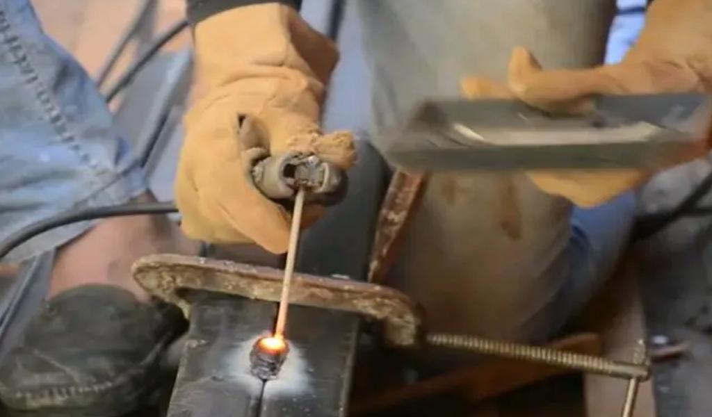
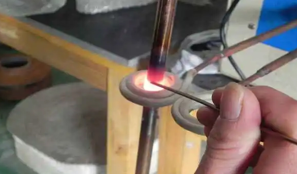
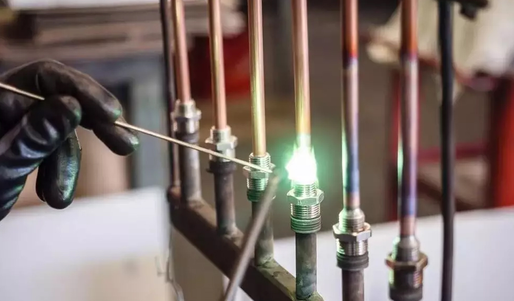
Brazing
Here’s an overview of the brazing process:
Basic Equipment:
- Base Metals: The materials being joined, often referred to as the workpieces.
- Filler Metal: A metal alloy with a lower melting point than the base metals. The filler metal is used to create the joint.
- Flux: A substance that helps to clean and prepare the surfaces of the base metals by removing oxides. It also promotes wetting and capillary action of the molten filler metal.
- Heat Source: Can be an open flame, induction, or resistance heating, depending on the specific brazing method.
Brazing Process:
- Surface Preparation: Clean the surfaces of the base metals to be joined to remove any contaminants and oxides.
- Flux Application: Apply flux to the joint area to protect the surfaces from oxidation during the heating process.
- Assembly: Position the workpieces together, ensuring proper fit-up for the joint.
- Heating: Apply heat to the assembly using a torch, furnace, or other heating methods. The heat source melts the filler metal, which flows into the joint due to capillary action.
- Wetting and Capillary Action: The molten filler metal wets the surfaces of the base metals and is drawn into the joint by capillary action.
- Cooling: Allow the joint to cool and solidify, forming a strong bond between the base metals.
Advantages:
- Joining Dissimilar Metals: Brazing is well-suited for joining dissimilar metals and materials with different melting points.
- Less Thermal Distortion: Since the base metals do not melt, there is less thermal distortion and minimal heat-affected zone.
- High Joint Strength: Brazed joints can exhibit high strength and can often be stronger than the base metals.
Disadvantages:
- Limited Joint Strength in High-Temperature Applications: Compared to welding or other joining methods, brazed joints may not be suitable for applications with extremely high temperatures.
- Visible Joint Line: The joint line may be visible, depending on the application and the specific brazing method used.
Applications:
- Brazing is commonly used in the production of various products, including heat exchangers, automotive components, electrical connectors, and jewelry.
- It is often employed in applications where the joined materials have different thermal expansion rates.
- Brazing is suitable for creating strong and leak-tight joints in situations where welding may not be practical.
The specific choice of filler metal and flux depends on the materials being joined and the requirements of the application. Brazing offers versatility and is widely used in different industries for creating durable and reliable joints.
Electroslag Welding
Here’s an overview of the electroslag welding process:
Basic Equipment:
- Electroslag Welding Machine: Provides the electrical power needed for the welding process.
- Electrode: A consumable, continuously fed electrode is used to initiate the arc and start the melting process.
- Flux: A granular flux is added to the joint, which plays a crucial role in creating the molten slag and protecting the weld pool.
- Mold Assembly: A mold assembly surrounds the joint, containing the molten slag and supporting the molten metal until it solidifies.
Electroslag Welding Process:
- Setup: The joint is prepared, and the workpieces are positioned with a small gap between them.
- Flux Application: Granular flux is added to the joint area, surrounding the electrode and the gap between the workpieces.
- Arc Initiation: An initial arc is struck between the electrode and the workpieces. This arc initiates the melting process.
- Electroslag Process: As the arc heats the electrode and the flux, a conductive molten slag is formed. The slag acts as a resistive medium, generating heat and shielding the weld pool.
- Continuous Feeding: The consumable electrode is continuously fed into the molten slag, providing a continuous supply of molten metal to fill the joint.
- Mold Support: The mold assembly contains and supports the molten metal until it solidifies into a weld joint.
- Weld Completion: The electrode is withdrawn, and the welded joint is allowed to cool and solidify.
Advantages:
- High Productivity: Electroslag welding is well-suited for welding thick sections, and it can provide high deposition rates.
- Deep Penetration: It allows for deep penetration into the workpieces, resulting in strong welds.
- Minimal Distortion: The process minimizes distortion and produces welds with low heat-affected zones.
Disadvantages:
- Vertical Welding: Electroslag welding is primarily suitable for vertical welding applications.
- Specialized Equipment: The process requires specialized equipment, making it less versatile than some other welding methods.
- Limited to Certain Materials: Electroslag welding is mainly used for low-alloy steels and some stainless steels.
Applications:
- Heavy Fabrication: Electroslag welding is commonly used in heavy fabrication industries, such as shipbuilding, bridge construction, and the manufacturing of large structural components.
- Pressure Vessel Manufacturing: It is employed for welding thick sections in the production of pressure vessels and storage tanks.
- Construction of Large Components: Applications where the efficient welding of large and thick components is required.
While electroslag welding is not as versatile as some other welding methods, it excels in specific applications where high productivity and deep penetration are crucial. The process is particularly well-suited for vertical welding of thick materials in heavy manufacturing and construction industries.
High-Frequency Welding
Here’s an overview of both processes:
High-Frequency Resistance Welding (HFRW)
Basic Equipment:
- High-Frequency Generator: Produces high-frequency electrical currents.
- Electrode Rolls: Apply pressure to the edges of the material being welded.
- Tube or Pipe Mill: Shapes and forms the material into the desired tube or pipe configuration.
HFRW Process:
- Material Preparation: Flat strips of the material are prepared, often with a slight V-shape to facilitate welding.
- Edge Heating: The edges of the material are heated by the high-frequency electrical current, causing them to soften and become more malleable.
- Welding: The softened edges are pressed together by the electrode rolls, forming a high-frequency resistance weld.
- Seam Heating: Additional high-frequency currents are applied to the seam to heat and forge the welded area.
- Squeeze Rolls: Further compress the welded seam to ensure proper consolidation.
Advantages:
- High Speed: HFRW can achieve high welding speeds, making it suitable for high-volume production.
- Efficient for Thin-Walled Tubes: Well-suited for welding thin-walled tubes and pipes.
- Good for Continuous Production: Often used in continuous production processes.
Disadvantages:
- Limited Thickness: Primarily suitable for thin-walled materials.
- Material Limitations: Certain materials may not be suitable for HFRW.
High-Frequency Induction Welding (HFIW)
Basic Equipment:
- High-Frequency Generator: Produces high-frequency electrical currents.
- Induction Coil: Surrounds the tube or pipe and induces an electric current in the material.
- Tube or Pipe Mill: Shapes and forms the material into the desired configuration.
HFIW Process:
- Material Preparation: Flat strips of the material are prepared.
- Induction Heating: The material passes through the induction coil, where high-frequency electrical currents are induced in the edges of the strip, causing localized heating.
- Welding: The heated edges are pressed together to create a solid-state weld.
- Seam Forging: Additional pressure and heat are applied to forge the weld seam and achieve consolidation.
- Sizing Section: Shapes the welded tube or pipe to its final dimensions.
Advantages:
- Versatile Thickness Range: HFIW is capable of welding a broader range of material thicknesses compared to HFRW.
- Higher Efficiency: Offers higher efficiency and less material waste compared to traditional welding processes.
- Reduced Heat-Affected Zone: Produces a smaller heat-affected zone, preserving material properties.
Disadvantages:
- Equipment Complexity: The induction coil and associated equipment can be complex and require careful control.
- Initial Setup Costs: The initial setup costs can be higher compared to some traditional welding methods.
Applications:
Both HFRW and HFIW are commonly used in the production of tubes and pipes for various industries, including:
- Steel Pipe Manufacturing: High-frequency welding is widely used in the production of steel pipes for applications such as oil and gas transportation, construction, and structural components.
- Automotive Industry: Used for manufacturing exhaust pipes and other tubular components.
- Appliance Industry: Commonly employed in the production of components for appliances such as refrigerators and air conditioners.
In summary, high-frequency welding processes are efficient methods for producing welded tubes and pipes, with each method having its advantages and specific applications. The choice between HFRW and HFIW depends on factors such as material thickness, production volume, and the desired characteristics of the final product.
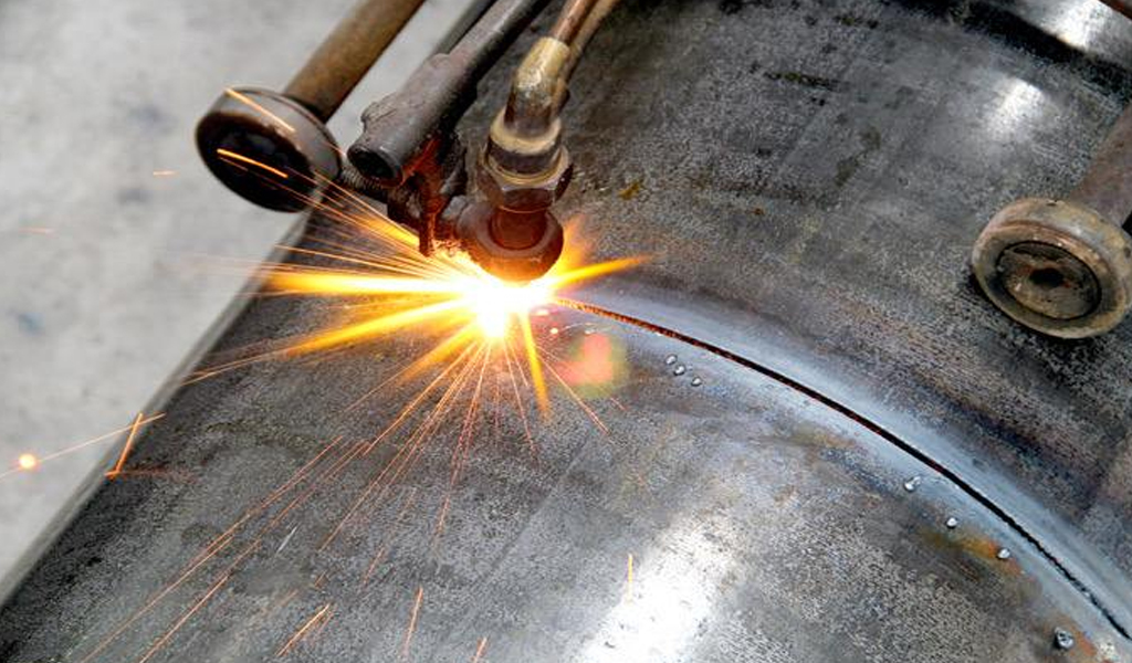
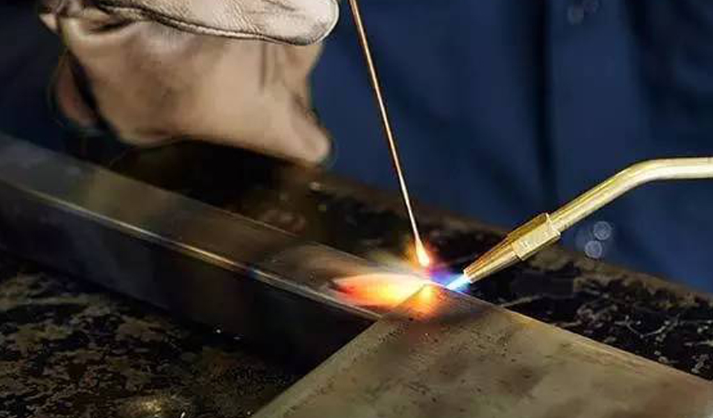
Gas welding
Here’s an overview of the gas welding process:
Oxy-Acetylene Welding (OAW):
Basic Equipment:
- Oxygen Cylinder: Contains high-pressure oxygen.
- Acetylene Cylinder: Contains high-pressure acetylene.
- Regulators: Control the flow and pressure of oxygen and acetylene.
- Torches: A welding torch with a mixing chamber for combining oxygen and acetylene and a flame tip for heating and welding.
- Welding Rods or Filler Metal: Additional metal may be added to the joint as needed.
OAW Process:
- Gas Cylinder Setup: Connect the oxygen and acetylene cylinders to the regulators.
- Regulator Adjustment: Adjust the regulators to achieve the desired pressures for oxygen and acetylene.
- Lighting the Torch: Open the oxygen and acetylene valves and ignite the mixture using a spark or a pilot flame.
- Adjusting the Flame: Adjust the torch controls to achieve a neutral, carburizing, or oxidizing flame based on the welding requirements.
- Preheating: Preheat the base metal using the outer cone of the flame until it reaches the proper temperature for welding.
- Welding: Direct the inner cone of the flame onto the joint area, and if necessary, add filler metal to create the weld.
- Cooling: Allow the welded area to cool gradually to minimize stress.
Advantages:
- Versatility: Oxy-acetylene welding can be used for welding, cutting, brazing, and heating.
- Portability: The equipment is relatively portable, making it suitable for on-site work.
- Cost-Effective: Equipment costs are generally lower compared to some other welding methods.
Disadvantages:
- Limited Thickness: Oxy-acetylene welding is most effective on thin to medium thickness materials.
- Slower Process: It is generally slower than some modern welding processes.
- Not Suitable for All Metals: Limited applicability for welding certain metals like aluminum.
Oxy-Fuel Welding (OFW):
Oxy-fuel welding is a broader term that encompasses the use of other fuel gases, such as propane or natural gas, in addition to acetylene. The process is similar to oxy-acetylene welding, with adjustments made to the equipment and parameters depending on the fuel gas used.
Applications:
- Oxy-fuel welding is commonly used in maintenance and repair work, as well as in industries like construction, fabrication, and automotive repair.
- It is suitable for welding ferrous and non-ferrous metals, cutting, and brazing.
In summary, gas welding, whether using acetylene or other fuel gases, remains a versatile and widely used process, especially in applications where portability and flexibility are essential. While modern welding processes have gained prominence in certain industries, gas welding continues to have its place for specific applications and remains a valuable skill for welders.
Pressure Gas Welding
Here’s an overview of the pressure gas welding process:
Basic Equipment:
- Pressure Gas System:
- Fuel Gas Cylinder: Contains high-pressure fuel gas (e.g., propane).
- Oxygen Cylinder: Contains high-pressure oxygen.
- Pressure Regulators: Control and regulate the flow and pressure of the fuel gas and oxygen.
- Welding Torch:
- Mixing Chamber: Combines the fuel gas and oxygen in the correct proportions.
- Nozzle: Shapes and directs the flame for heating and welding.
- Control Valves: Regulate the flow of fuel gas and oxygen.
- Welding Rods or Filler Material:
- Additional metal may be added to the joint as needed.
Pressure Gas Welding Process:
- Gas Cylinder Setup:Connect the fuel gas and oxygen cylinders to the pressure regulators.Adjust the regulators to achieve the desired pressures for fuel gas and oxygen.
- Lighting the Torch:Open the fuel gas and oxygen valves on the torch.Ignite the gas mixture at the nozzle using a spark or pilot flame.
- Adjusting the Flame:Adjust the control valves to achieve the appropriate flame characteristics for welding (neutral, carburizing, or oxidizing).
- Preheating:Preheat the base metal using the outer envelope of the flame until it reaches the desired temperature for welding.
- Welding:Direct the inner cone of the flame onto the joint area to create the weld.Add filler metal if necessary to fill the joint.
- Cooling:Allow the welded area to cool gradually to minimize stress.
Advantages:
- Suitable for Thick Sections: Pressure gas welding is effective for welding thick sections of metal.
- Versatility: It can be used for welding, cutting, and other heating applications.
- Cost-Effective: Equipment costs are generally lower compared to some other welding methods.
Disadvantages:
- Limited to Certain Materials: It is more commonly used for ferrous metals and may not be as suitable for welding non-ferrous metals.
- Not as Portable: The equipment can be less portable compared to oxy-acetylene equipment.
- Skill Requirement: Achieving high-quality welds requires skill and experience.
Applications:
Pressure gas welding is commonly used in heavy fabrication, construction, and shipbuilding industries. It is suitable for welding thick sections of ferrous metals, and its versatility allows for applications such as cutting and heating in addition to welding.
While pressure gas welding has been largely replaced by other welding processes in certain applications, it still finds use in specific industries and situations where its characteristics are advantageous. The choice of welding method depends on factors such as material thickness, application requirements, and the availability of equipment.
Explosive Welding
Here’s an overview of the explosive welding process:
Basic Equipment:
- Base Plates:The two materials to be joined, often referred to as the flyer plate (upper plate) and the base plate (lower plate).
- Explosive Material:A layer of explosive material, typically composed of plastic, chemical compounds, or sheet explosive.
- Detonators and Initiation System:Detonators or other initiation systems to initiate the explosive reaction simultaneously across the surface.
Explosive Welding Process:
- Surface Preparation:Clean and prepare the surfaces of the flyer plate and base plate to ensure proper bonding.
- Assembly:Place the flyer plate and base plate in intimate contact with each other, ensuring a close fit.
- Explosive Layer Application:Apply the layer of explosive material onto the surface of the flyer plate.
- Detonation:Simultaneously initiate the explosive material using detonators or other initiation systems.
- Explosive Reaction:The explosive material undergoes a detonation, generating a shockwave that accelerates the flyer plate towards the base plate at a high velocity.
- Impact and Bonding:The flyer plate impacts the base plate with high velocity, creating extreme pressure at the interface.The pressure and temperature at the interface cause the materials to bond metallurgically without melting.
- Cooling and Solidification:Allow the welded area to cool and solidify, forming a strong and durable bond.
Advantages:
- Joining Dissimilar Metals: Effective for joining materials with different properties, such as metals with significant differences in melting points.
- No Heat-Affected Zone (HAZ): Since the process is solid-state, there is minimal heat input, and no melting occurs, resulting in no HAZ.
- High Bond Strength: Creates strong metallurgical bonds with good mechanical properties.
Disadvantages:
- Limited to Certain Applications: Primarily used for specific applications where other welding methods may not be suitable.
- Specialized Equipment: The process requires careful control of explosive materials and initiation systems.
- Surface Finish: The bonded area may require post-weld machining or surface treatment.
Applications:
- Cladding: Used for cladding one metal onto another, providing improved corrosion resistance or other properties.
- Bi-metallic Components: Fabrication of components with dissimilar metals, such as transition joints for connecting aluminum to steel in the shipbuilding industry.
- Laminates and Composites: Production of laminates and composites for various industrial applications.
Explosive welding is a niche welding process employed in specific applications where the unique characteristics of the process, such as joining dissimilar metals without melting, are advantageous. It requires careful planning, expertise, and safety measures due to the explosive nature of the process.
Friction Welding
Here are some common types:
1. Rotary Friction Welding
Basic Equipment:
- Rotary Spindle: Holds one of the workpieces and provides rotation.
- Chuck: Holds the other workpiece against the spindle.
- Control System: Manages the rotational speed, pressure, and time parameters.
Process:
- Contact: The workpieces are brought into contact under pressure.
- Rotation: One of the workpieces is rotated against the stationary workpiece.
- Friction Heating: The heat generated due to friction softens the materials at the interface.
- Forge Pressure: Once the desired temperature is reached, rotation stops, and axial pressure is applied to forge the materials together.
- Cooling: The welded area is allowed to cool.
Advantages:
- Efficient for cylindrical components.
- Suitable for both similar and dissimilar materials.
- High production rates.
2. Linear Friction Welding
Basic Equipment:
- Linear Drive System: Moves one workpiece linearly.
- Chuck or Holder: Holds the other workpiece against the linear motion.
- Control System: Manages linear motion, pressure, and time parameters.
Process:
- Contact: The workpieces are brought into contact under pressure.
- Linear Motion: One workpiece is moved linearly against the stationary workpiece.
- Friction Heating: Heat is generated due to friction between the materials.
- Forge Pressure: Once the desired temperature is reached, linear motion stops, and axial pressure is applied to forge the materials together.
- Cooling: The welded area is allowed to cool.
Advantages:
- Suitable for various shapes and sizes.
- Effective for large or irregularly shaped components.
- High precision and repeatability.
3. Friction Stir Welding (FSW)
Basic Equipment:
- Shoulder: Applies downward force on the workpieces.
- Rotating Pin: Generates frictional heat and stirs the materials.
- Control System: Manages rotation speed, traverse speed, and axial force.
Process:
- Contact: The rotating pin is plunged into the joint between the workpieces.
- Rotation and Traverse: The pin rotates and traverses along the joint line, generating frictional heat.
- Plasticization: The heat plasticizes the materials without melting.
- Forge Pressure: Axial force is applied to forge the materials together.
- Cooling: The welded area is allowed to cool.
Advantages:
- Particularly suitable for joining heat-sensitive materials.
- Effective for aluminum and other non-ferrous alloys.
- Excellent for producing high-strength, defect-free welds.
Friction welding processes offer several advantages, including the absence of filler material, minimal heat-affected zones, and high joint efficiency. These processes are widely used in aerospace, automotive, and other industries where strong and reliable joints are required.
Ultrasonic Welding
Here’s an overview of ultrasonic welding:
Basic Equipment:
- Ultrasonic Welding Machine:Consists of an ultrasonic generator, transducer, and welding horn.The ultrasonic generator produces electrical energy at a high frequency.The transducer converts the electrical energy into mechanical vibrations.The welding horn focuses and transmits the vibrations to the joint.
- Fixture:Holds the parts in place during the welding process.
- Anvil:Supports the parts opposite the welding horn.
Ultrasonic Welding Process:
- Part Preparation:The parts to be joined are positioned in the fixture with precise alignment.
- Clamping:The fixture clamps the parts together.
- Ultrasonic Vibration:The ultrasonic generator produces high-frequency vibrations.The transducer converts the electrical energy into mechanical vibrations.The welding horn focuses these vibrations onto the joint interface.
- Frictional Heating:The focused vibrations create friction at the joint interface, generating heat.In the case of thermoplastics, the heat softens and melts the material.
- Welding Pressure:The ultrasonic vibrations, combined with the clamping force, cause the softened materials to fuse together.
- Cooling:Once the joint is formed, the vibrations cease, and the material cools and solidifies.
Advantages:
- Speed: Ultrasonic welding is a fast process, making it suitable for high-volume production.
- Precision: Provides precise control over the welding process.
- Minimal Heat-Affected Zone: Since the process is solid-state, there is minimal heat transfer to the surrounding areas.
- No Consumables: Typically, no additional materials or filler are required.
Disadvantages:
- Material Limitations: Primarily used for thermoplastics, and certain metals, ceramics, and composites.
- Joint Design: Joint design and geometry can affect the quality of the weld.
Applications:
- Plastic Industry: Commonly used for joining thermoplastic components in industries such as automotive, electronics, and medical devices.
- Textile Industry: Used for bonding synthetic fabrics.
- Metal Welding: Applied to thin metal foils and sheets in certain applications.
Ultrasonic welding is favored for its speed, precision, and ability to create strong and reliable joints in thermoplastics. It is particularly useful in industries where non-destructive and efficient welding of plastic components is required. The process is also environmentally friendly, as it does not involve the use of adhesives or consumables.
Diffusion Welding
Here’s an overview of the diffusion welding process:
Basic Equipment:
- Workpieces:The materials to be joined, often in the form of flat plates or cylindrical components.
- Pressure System:Provides the compressive force necessary for the materials to bond.
- Heating System:Raises the temperature of the workpieces to the diffusion temperature.
Diffusion Welding Process:
- Surface Preparation:The surfaces of the workpieces are meticulously cleaned and prepared to ensure a high-quality joint.
- Assembly:The workpieces are brought into intimate contact with each other.
- Heating:The assembly is subjected to elevated temperatures, typically below the melting point of the materials but high enough to allow atomic diffusion to occur.
- Application of Pressure:A compressive force is applied to the workpieces to promote atomic diffusion across the joint interface.
- Diffusion Bonding:The atoms at the joint interface migrate and diffuse, forming metallurgical bonds between the workpieces.
- Cooling:The assembly is allowed to cool, and the joint solidifies.
Advantages:
- Metallurgical Bond: Diffusion welding results in a strong metallurgical bond between the workpieces.
- No Fusion or Melting: The process is conducted at temperatures below the melting point, reducing the risk of thermal distortion and preserving material properties.
- Suitable for Dissimilar Materials: Effective for joining dissimilar materials with different melting points or properties.
- Minimal Distortion: Since there is no molten metal involved, there is minimal thermal distortion.
Disadvantages:
- Equipment Complexity: Diffusion welding equipment can be complex and may require precise control of temperature and pressure.
- Limited to Certain Materials: More commonly used for high-temperature and high-strength materials.
- Slower Process: The process can be relatively slow compared to some fusion welding methods.
Applications:
- Aerospace Industry: Used for joining components in aircraft engines and other high-performance applications.
- Power Generation: Applied in the production of components for gas turbines and other power generation systems.
- Automotive Industry: Utilized for manufacturing certain engine components.
- Nuclear Industry: Diffusion welding is used for producing components in nuclear reactors.
Diffusion welding is a specialized process suitable for specific applications where the preservation of material properties and the creation of strong metallurgical bonds are critical. While it may not be as widely used as some fusion welding methods, diffusion welding is valued in industries where the properties of the joint are of utmost importance, particularly in high-temperature and high-stress environments.
The Detail Of BE-CU Sheet Metal Company
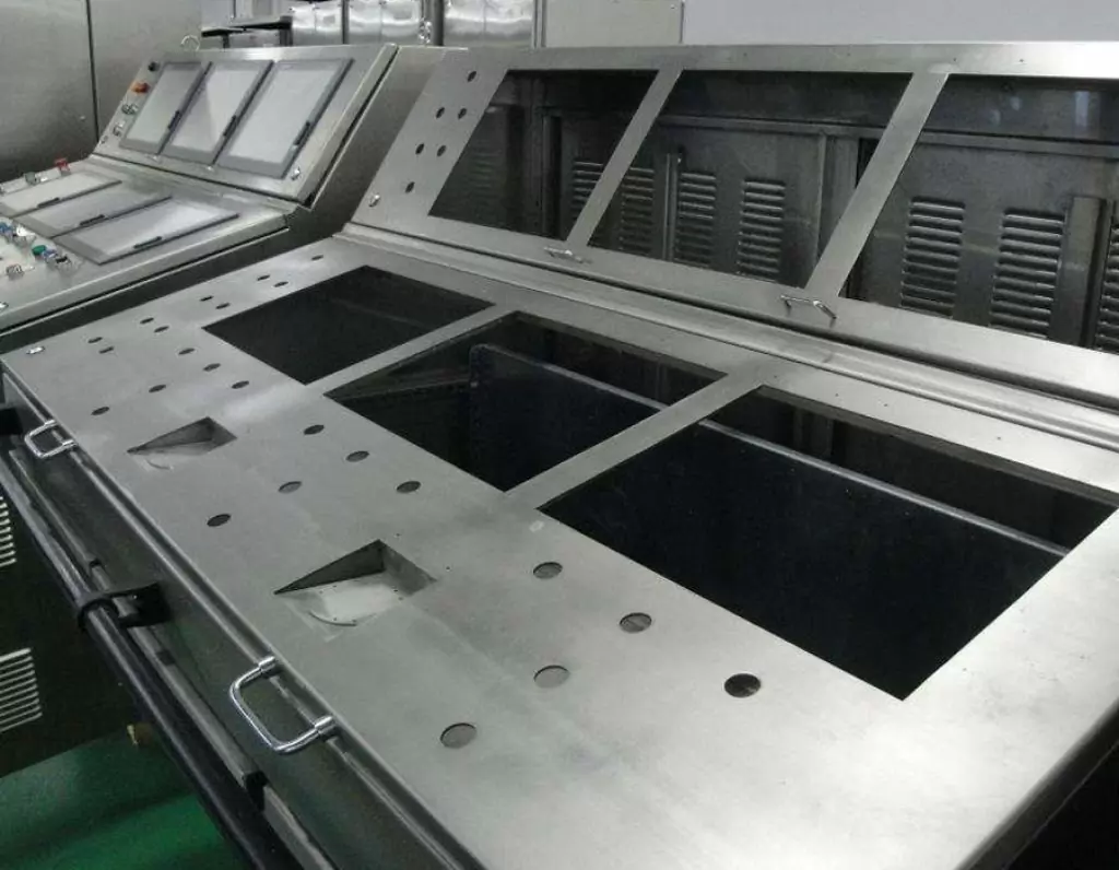
BE-CU is a professional and technical enterprise engaged in sheet metal fabrication, with over 2000 m2 sheet metal workshop and has one-stop service of industrial automation R&D, production, processing and sales.Custom manufacturer of sheet metal component assemblies made from stainless steel, aluminum and carbon steel. Offered in different specifications and features.Markets served include aerospace, lighting, medical, defense, semiconductor/electronics, capacitor, chemical processing and energy.Capable of maintaining dimensional tolerance up to +/-0.005 in. Capabilities include contract manufacturing, fabrication, machining, bending, milling, cutting, forming, drilling, fitting, assembly, notching, punching, rolling, turning, CNC press braking, flame and high definition plasma cutting, saw cutting, shearing, prototyping, high volume, short run and long run production and MIG, TIG and arc welding. Secondary services include Blanchard grinding, galvanizing and painting.
-
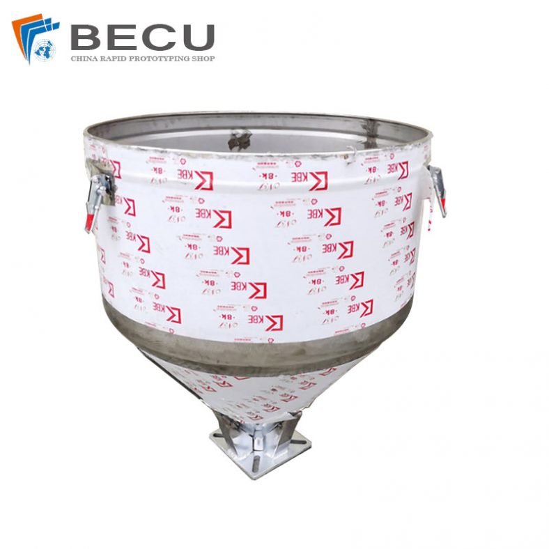
Sheet Metal Fabrication Injection Molding Machine Hopper
-
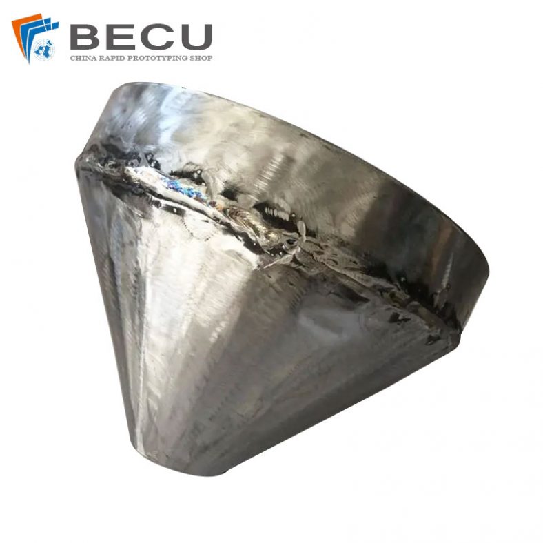
Sheet Metal Fabrication Funnel For Agricultural Machinery
-
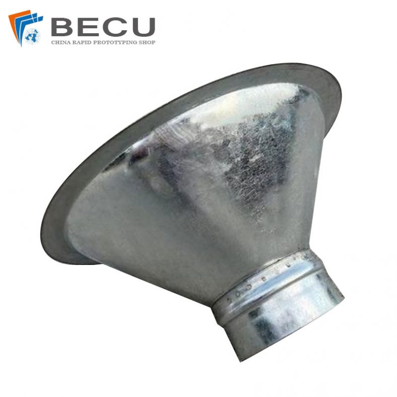
Sheet Metal Fabrication Galvanized Spiral Air Duct
-
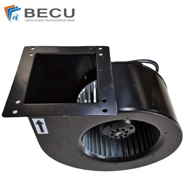
PCS Fan Ductwork Sheet Metal Housing
-
Custom Sheet Metal Surgical Instrument Sterilization Box For Beauty Salon
-
Precision Fabrication Green Energy EV Charging Station Cabinet
-
TA1TA2 Alloy Sheet Metal Manufacturing Machinery Support Parts
-
Sheet Metal Fabrication Aluminum 5052 Medical Box For Fire Fighting