
Through the description and introduction of the product development of the oil pan stamping parts of construction machinery, the representative oil pans in various aspects such as the analysis of the stamping process, the product stamping process, and the oil pan die manufacturing technology involved in the development of this product are explained. Shell Product Technology.
The oil pan product is very difficult to stamp, and the technical requirements for tooling manufacturing and maintenance are high, so it has always been a difficulty for stamping products in the engine assembly.
This paper expounds from the analysis of product technology of construction machinery oil pan, product modification, to the development and manufacture of tooling and mold. Keywords: oil pan, stamping, construction machinery.
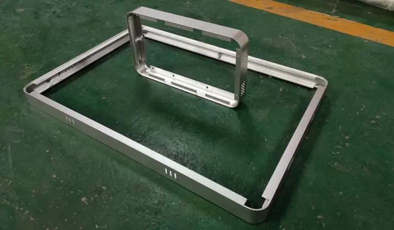
Product Description
Construction machinery oil pan is mainly used in construction machinery engine, it is characterized by large oil storage capacity and strong versatility. It is a product with a promising future. This product has a certain difference from my previous A oil pan: the shape is basically symmetrical. Different from the previous oil pan, there is no deep and shallow end, only an oil storage tank in the middle.
Because the product has three deep ribs on both shoulders. This increases the difficulty of drawing and increases the possibility of drawing limits.
In order to improve the product quality of the construction machinery oil pan and prolong the service life of the mold, combined with the quality defects (pull marks) of the current production A oil pan drawing, the shaping surface is difficult to process and easy to wear and punching has been using two sets of molds combined. The cost of installation is wasted, and a new process and new structure process plan is finally determined.
Process Technology Analysis
There is an oil sump on the oil pan of construction machinery, and there are three deep ribs on both shoulder ends.
There are sealing embossing on the flange surface of construction machinery oil pan.
The previous design of the flange surface of the oil pan is flat. The oil pan is installed on the engine block, and the flange surface of the oil pan is mainly fixed with screws to press the sealing ring to prevent oil leakage. However, in actual use, oil often leaks between the two screw holes. After analyzing and studying the disassembled oil pan with oil leakage, it was found that the flange surface between the two screw holes was raised. The reason is that after tightening the screws, the flange surface of the oil pan is undulating and deformed, the parts that are stressed are concave, and the parts that are not stressed are raised. Oil oozes out from the bulge.
To prevent similar oil spills from happening again. Cummins adopts a new design scheme: add a 3.2mm×18.5mm plane between the screw holes on the flange surface of the oil pan, and it is 0.38mm higher than the screw hole surface. When screwing, due to the elastic deformation of the sheet material, the pressure on the flange surface between the two screw holes will continue to increase as the screws are tightened, and finally the entire flange surface is completely crushed, which theoretically solves the oil pan method. The problem of oil leakage on the blue noodles.
The construction machinery oil pan adopts the above structure.
Production requirements
Production varieties and methods: multi-variety mixed-flow production. Stamping quality requirements: the surface of the parts has no pits, scratches, wrinkles, extremes and cracks. The embossing is clear and the embossing is obvious. Flanging to size, punching and trimming without obvious burrs.
Product manufacturability analysis
since the maximum drawing height is only 218mm, during the drawing process, the corners are not easy to crack, but the slopes on both sides are too steep and easy to crack. At the transition positions of the four corners, wrinkles are prone to occur due to uneven material flow. At present, in the manufacturing process of the oil pan, methods such as smearing drawing oil and padding plastic sheets are often adopted to balance the flow speed of the material, and multiple drawing methods are used to solve the above phenomena.
Analyzing the oil pan products of construction machinery, from the point of view of the stamping process, due to the difference in the flow of materials up and down and the left and right of the oil pan, and the large pressing area at the same time, the balanced flow of materials is hindered. What is beneficial to the craftsmanship is the design of the bulge at the four corners of the product. The design of the bulge effectively absorbs the excess material at the corners, prevents the accumulation of materials, and reduces the possibility of drawing and wrinkling.
Process experiment and comparative analysis
The following is a CAE analysis of the original product:
The original product was drawn twice, and at the end of the second drawing, cracking occurred.After analysis, it is considered that from the product stamping process
The following modifications should be made to the product from a sexual perspective:
After discussions with the technical staff of the construction machinery oil pan project, the above revisions were proposed and feedback was received. We believe that the draft angle of the side wall of the product is only 1.5mm, which has a certain impact on the stamping process of the part. In addition, the depth of the rib is 12.8mm, and the rapid transition of the material from the plane to the deep rib will inevitably lead to faster flow and deformation. Violent, unable to meet the requirements of the stamping process. The customer believes that raising the height of the rib by 6mm will not affect the assembly of other mechanisms of the engine assembly at this position, so he agrees with the revised opinion.
We performed CAE analysis on the changed product, and the results are shown in Figure 11:
It can be seen from Figure 11 that the area with the largest local material thinning rate is 7%. in a safe area. From the above results, it can be seen that the risk of cracking has been basically eliminated for the modified product, and the CAE analysis of the part shows that the part is still in a safe state after the two drawing processes are completed. From past experience, it can be guaranteed that qualified drawn products can be debugged.
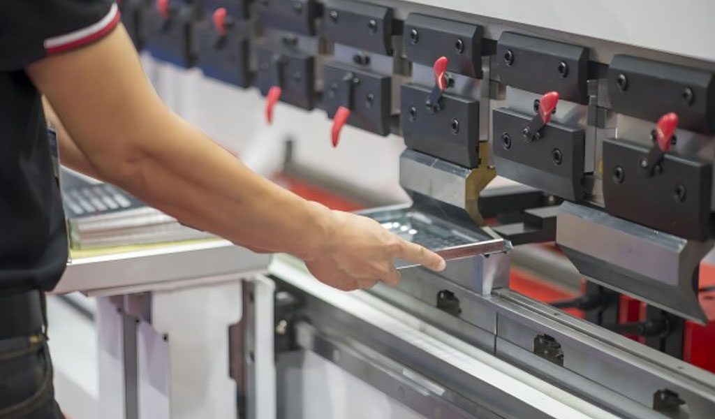
Stamping Process Analysis
Due to the regular structure of the product, the depth of the stamping process is not deep. In addition to the holes on the flange surface, there are two oil holes, so two deep drawing and three punching are used to complete the entire part.
We propose and verify that the 80 and 90 sequences can use one hanging wedge, one oblique wedge, and one drive to achieve two angled holes punched by a set of molds, saving the design cost, processing cost, material cost, labor cost of a set of molds cost.
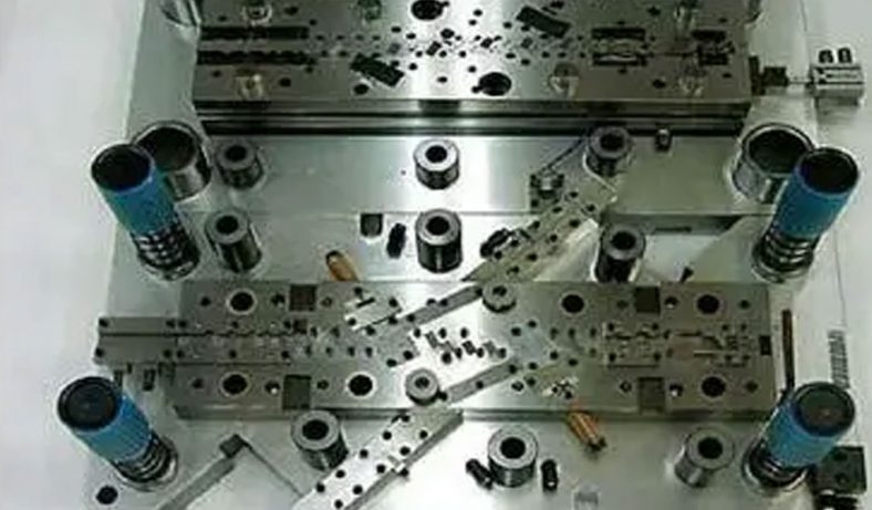
Mold Design Situation
After the stamping process verification, the problems in the mold design stage are much less, and rich experience has been accumulated in the previous oil pan mold design. Therefore, the problem in the mold design process is to summarize the past experience and carry out in the new development project. application.
The insert-type structure is adopted in the mold design to ensure the wear resistance of the working part. On the basis of CAE, the unnecessary work surface is effectively reduced, and the material cost is saved.
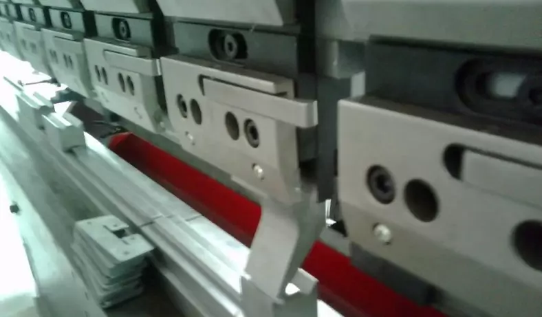
In the design of the die for punching the flange face, the previous experience is broken, and the die is placed on the lower die, so that the die can be inserted and replaced easily. Moreover, the oil pan buckle is placed on the mold, which is easy to take out, which saves the time for taking out the parts during stamping.
For the first time, we boldly used one hanging wedge, one oblique wedge and one drive to punch two angled holes with one set of molds, saving the design cost, processing cost, material cost and labor cost of a set of molds.
Mold Manufacturing
Due to the first deep drawing, the deep drawing fillet is hardened, and the second deep drawing makes it difficult to deform the hardened fillet material again, forming a wrinkled bulge. The wrinkling bulge was eliminated by increasing the deep draw fillet of a draw and adding an over-bevel at the root of the side groove, as shown in Figure 26.
Using a new heat treatment process, the alloy inserts used on the drawing die are subjected to PVD treatment to enhance the wear resistance of the alloy inserts, so as to achieve no lubricating oil before drawing, no plastic film pads, and no wear of the inserts. The pull marks on the side of the oil pan do not appear.PVD technical requirements:
- 1. The original hardness of the substrate is HRC58-62, and the hardness after PVD is not less than HRC53;
- 2. Before doing PVD, the surface of the substrate should be infiltrated with a nitride layer larger than 0.8mm;
- 3. PVD adopts CrN coating;
- 4. The deformation of the insert after PVD is not more than 0.1mm;
- 5. There is no crack in the insert after PVD.
In Conclusion
- The oil sump of construction machinery adopts PVD surface hardening process, which eliminates the long-standing quality problems such as pull marks on the side of the oil sump and embossing wear.
- The oil pan of construction machinery is fully utilized by the hanging wedge and the wedge. For the first time, a set of molds can be driven to punch two holes with different angles on the oil pan, which saves the cost of the mold. 3. Designing the blanking die for the oil pan of construction machinery, using automatic sliding material, automatic aggregate material, saving labor cost, is our next research topic.
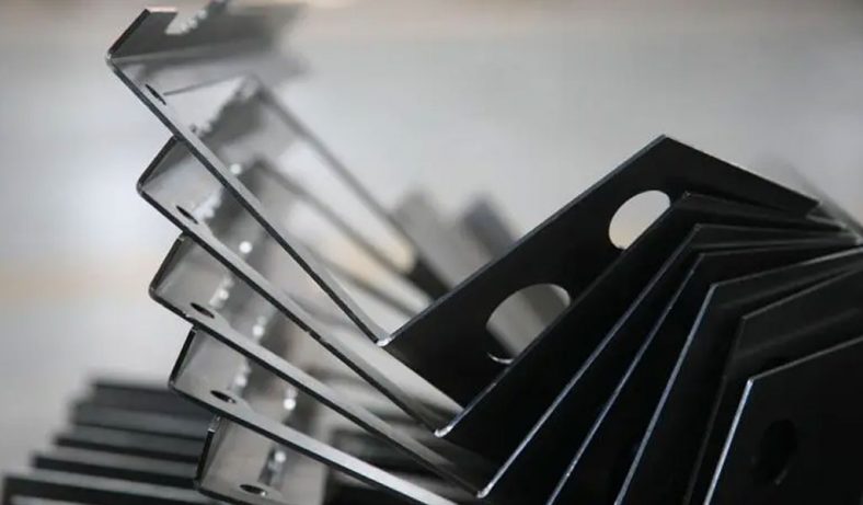
China Sheet Metal Fabrication Company
Sheet fabrication services for mild steel, high strength low alloy (HSLA) steel, cold/hot rolled steel, galvanized steel, stainless steel, aluminum, copper and brass. Capable of fabricating parts up to 12 ft. length and +/-0.001 in. tolerance. Various capabilities include contract manufacturing,custom stamping,edge rolling, forming,top laser cutting, roll bending and welding. Finishing and secondary services such as hardware installation, tapping, deburring, cleaning, heat treating, plating, anodizing and painting available. Sheet Metal Prototype and low to high volume production runs offered.
Suitable for commercial/residential architectural, aluminum brake shape parts, wall panel systems, brackets, general flashings, rails, call button plates and ship building component parts.If you want a specific material to be used in the sheet metal fabrication process, don’t hesitate to contact us!
-
Stainless Steel Sheet Metal Fabrication
-
Aluminum Sheet Metal Fabrication
-
Copper Sheet Metal Fabrication
-
Brass Sheet Metal Fabrication
-
Steel Sheet Metal Fabrication
-
Titanium Sheet Metal Fabrication
-
Galvanized Steel Sheet Metal Fabrication
-
Mild Steel Sheet Metal Fabrication
-
Bronze Sheet Metal Fabrication
Our Sheet Metal Fabrication Applications
Be-Cu prototype offers custom sheet metal fabrication for creating structures, machines, and parts that includes:
Our Case Studies Gallery Of Sheet Metal Fabrication Parts
If you need custom Sheet Metal Fabrication parts in China from a trusted supplier, look no further. Professional service from 10 to 100000+ parts,Whether you want a small series production or large quantities,Be-Cu Prototype scale precision Sheet Metal Fabrication services according to our customers needs, including pipe,plate and tube cutting. Contact us to see how we can help you! Get a quote today!
-
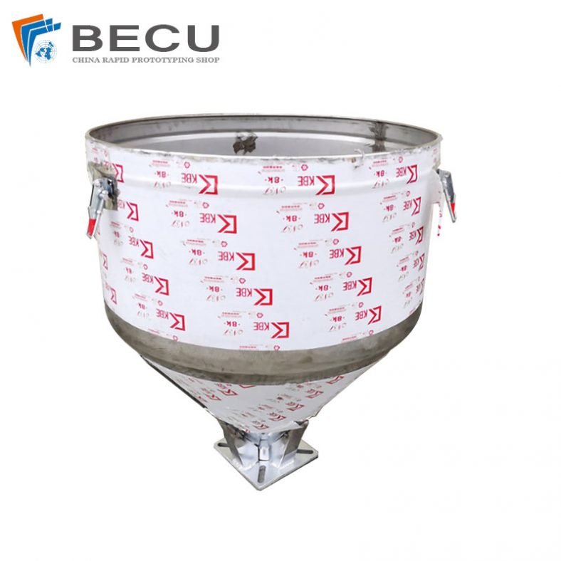
Sheet Metal Fabrication Injection Molding Machine Hopper
-
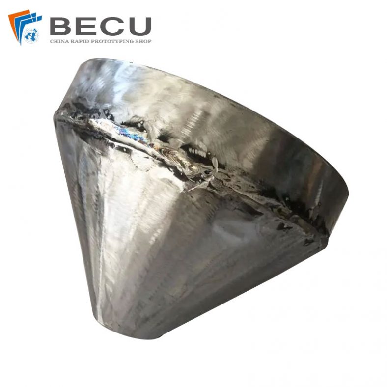
Sheet Metal Fabrication Funnel For Agricultural Machinery
-
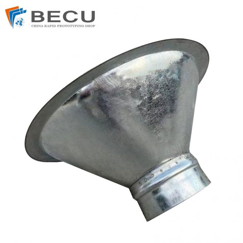
Sheet Metal Fabrication Galvanized Spiral Air Duct
-
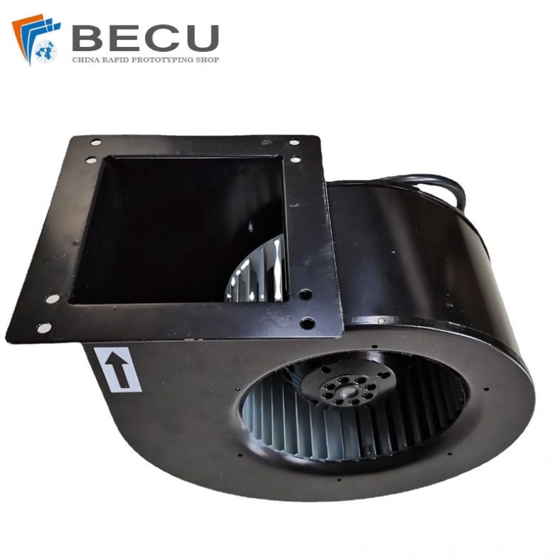
PCS Fan Ductwork Sheet Metal Housing
-
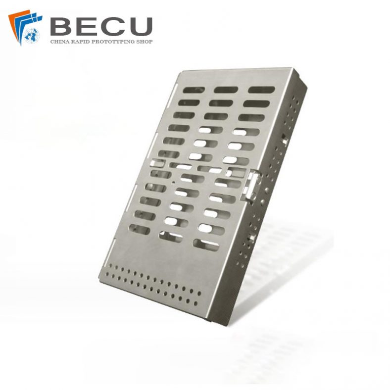
Custom Sheet Metal Surgical Instrument Sterilization Box For Beauty Salon
-
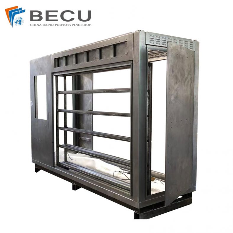
Precision Fabrication Green Energy EV Charging Station Cabinet
-
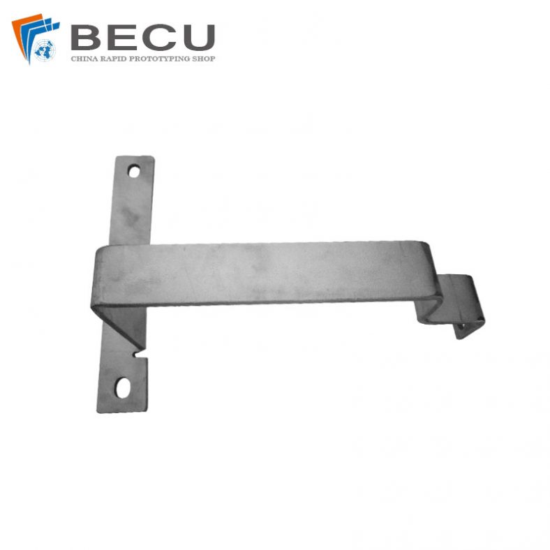
TA1TA2 Alloy Sheet Metal Manufacturing Machinery Support Parts
-
Sheet Metal Fabrication Aluminum 5052 Medical Box For Fire Fighting