
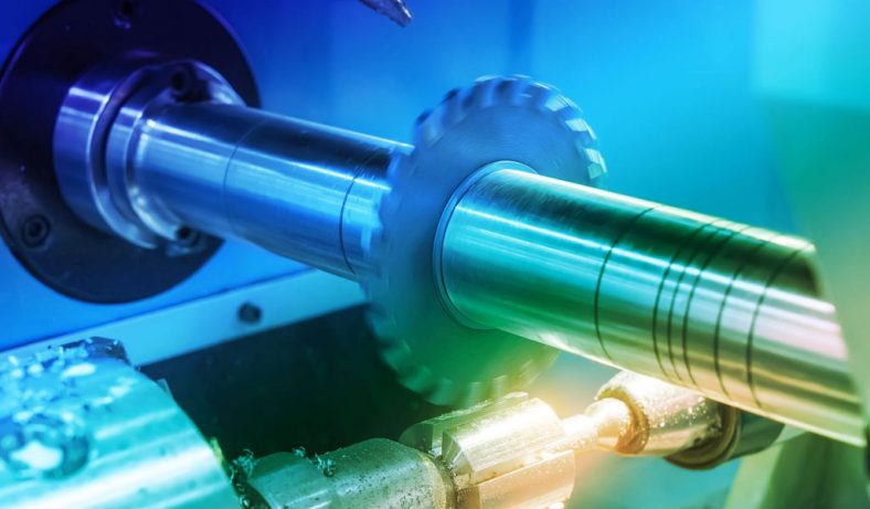
Lathe machines have played a pivotal role in the world of manufacturing for centuries. These versatile machines have evolved significantly, enabling a wide range of operations to be performed with high precision. One such operation is grooving, which involves the creation of grooves or recesses on a workpiece. In this comprehensive article, we will delve deep into the world of grooving operations in lathe machines. We will explore the tools, techniques, dimensions, and applications of grooving, providing valuable insights for both novice and experienced machinists.
View More Articles:
Introduction
Lathe machines have been at the forefront of machining operations for centuries, enabling the creation of intricate components and parts across various industries. These versatile machines, with their ability to shape materials with precision, are instrumental in manufacturing processes. One of the key operations performed on lathe machines is grooving, a fundamental technique that involves the creation of precise grooves or recesses on a workpiece.
Definition of Grooving Operation
At its core, grooving is a machining process that entails the removal of material to form grooves or channels on a workpiece. These grooves can serve various purposes, including providing clearance for other components, accommodating O-rings or seals, or simply enhancing the aesthetics of a part. Grooving operations can be performed both on the exterior and interior of a workpiece, making them a versatile and indispensable part of lathe machining.
Importance of Grooving in Lathe Machining
Understanding the significance of grooving in the realm of lathe machining is essential. Grooves are ubiquitous in numerous products, from automotive components to aerospace parts and consumer goods. They play a vital role in enhancing functionality, ensuring proper sealing, and improving the structural integrity of various products. As such, grooving operations are a critical skill for machinists and manufacturers alike.
Overview of Article Structure
This article is structured to provide a comprehensive and informative resource for anyone interested in grooving operations in lathe machines. It will delve into the intricacies of grooving tools, techniques, dimensions, and applications. Whether you are a seasoned machinist looking to refine your skills or a novice seeking to understand the fundamentals, this article aims to be your definitive guide.
The article is organized into twelve distinct sections, each offering valuable insights into different aspects of grooving operations:
- Lathe Machine Fundamentals: This section will provide a historical overview of lathe machines, discuss the various types, and explore the essential components that make these machines work.
- Lathe Grooving Tools: To perform grooving operations effectively, machinists require the right tools. This section will delve into the world of lathe grooving tools, exploring types, materials, geometries, and holders.
- Grooving Techniques: Successful grooving requires careful setup and execution. Here, we will explore the techniques involved in setting up a lathe machine for grooving, including selecting cutting speeds, feed rates, and depths of cut.
- Grooving Operations in Practice: Practical application is key to mastering grooving operations. This section provides step-by-step guides for both external and internal grooving, accompanied by case studies and practical examples.
- Dimensions and Tolerances in Grooving: Understanding groove dimensions and tolerances is crucial for precision machining. This section delves into the specifics of groove width, depth, length, and the associated tolerance requirements.
- Advanced Grooving Applications: Beyond basic grooving, this section explores advanced applications, including thread grooving, face grooving, multi-groove machining, and microgrooving.
- Materials and Tool Selection: The choice of materials for both the workpiece and cutting tools can significantly impact grooving operations. This section discusses matching cutting tools with workpiece materials, tool coatings, and considerations for sustainability and tool longevity.
- Optimizing Grooving Efficiency: Efficiency is a key concern in modern manufacturing. We will discuss the role of coolants and lubricants, compare CNC and manual lathe machining, and explore automation and robotics in grooving.
- Challenges and Future Trends: The machining industry is continually evolving. This section examines emerging technologies, such as Industry 4.0 and digitalization, and explores sustainability and eco-friendly practices in grooving.
- Conclusion: In the concluding section, we will summarize the key points discussed throughout the article, emphasizing the role of grooving in modern manufacturing, and provide encouragement for aspiring machinists.
- References: This section will list the sources used in compiling the article, allowing readers to explore specific topics in greater detail.
In the subsequent sections of this article, we will dive deeper into each of these topics, providing a comprehensive and informative resource for readers seeking to enhance their understanding of grooving operations in lathe machines.
Lathe Machine Fundamentals
2.1 Brief History of Lathe Machines
To appreciate the significance of lathe machines in modern machining, it’s essential to delve into their historical roots. Lathe machines have a rich history that spans millennia, with their evolution closely intertwined with the development of various civilizations.
- Ancient Origins: The concept of turning and shaping objects using a lathe-like mechanism can be traced back to ancient civilizations such as the Egyptians and the Mesopotamians, who used simple hand-operated lathes for woodworking. These early lathes allowed craftsmen to create intricate designs and cylindrical shapes.
- Medieval and Renaissance Periods: During the Middle Ages, lathe technology advanced further in Europe. Foot-operated lathes and spring-pole lathes became common tools for artisans and craftsmen. The Renaissance era saw significant improvements in lathe design, including the invention of the screw-cutting lathe by Leonardo da Vinci.
- Industrial Revolution: The Industrial Revolution of the 18th and 19th centuries brought about a revolution in machining technology. Innovations like the slide rest and the development of power lathes marked a turning point in lathe machine history. These advancements allowed for greater precision and efficiency in manufacturing.
- Modern Lathe Machines: The 20th century witnessed the proliferation of modern lathe machines. From conventional engine lathes to advanced CNC (Computer Numerical Control) lathes, these machines became essential in industries such as aerospace, automotive, and manufacturing.
Today, lathe machines have evolved into highly sophisticated and automated tools capable of performing complex operations with utmost precision.
Types of Lathe Machines
Lathe machines come in a variety of types, each designed for specific machining tasks. The choice of lathe type depends on factors such as the workpiece’s size, complexity, and material. Here are some common types:
- Engine Lathe: Also known as a center lathe or bench lathe, this is the most basic and versatile type of lathe. It is widely used for general-purpose machining, turning, and threading operations.
- CNC Lathe: Computer Numerical Control (CNC) lathes are highly automated and programmable machines. They are capable of precision machining and can produce intricate components with minimal human intervention.
- Turret Lathe: Turret lathes have a rotating tool turret that holds multiple cutting tools. This design enables quick tool changes and is suitable for high-volume production.
- Capstan Lathe: Similar to turret lathes, capstan lathes are designed for repetitive and high-speed machining of small to medium-sized parts. They often use collets for workpiece clamping.
- Gap Bed Lathe: Gap bed lathes have a removable gap section in the bed, allowing them to accommodate larger workpieces. This versatility makes them suitable for a wide range of applications.
- Swiss-Type Lathe: These lathes are specialized for precision machining of small, intricate parts, often used in the watchmaking and medical device industries.
- Multi-Spindle Lathe: Multi-spindle lathes have multiple spindles that can simultaneously machine multiple workpieces, increasing productivity in high-volume production.
- Facing Lathe: Facing lathes are designed specifically for facing operations, where the cutting tool moves radially across the workpiece’s face.
Components of a Lathe Machine
A lathe machine consists of several essential components that work together to perform machining operations. Understanding these components is crucial for operating and maintaining the machine effectively. Here are the key components of a lathe machine:
- Bed: The bed is the horizontal, rigid base of the lathe. It provides support for all other components and ensures the machine’s stability. The bed may be made of cast iron or other materials known for their strength and vibration-dampening properties.
- Headstock: The headstock is located at the left end of the lathe’s bed. It contains the main spindle, which rotates the workpiece. The spindle is powered by an electric motor and can be controlled for speed and direction.
- Tailstock: The tailstock is positioned at the right end of the lathe bed and serves as support for the workpiece opposite the headstock. It often includes a spindle that can be adjusted for various purposes, such as drilling or providing additional support to the workpiece.
- Carriage: The carriage is the assembly that moves along the length of the bed and holds the cutting tool. It consists of several components, including the saddle, cross-slide, and compound rest. The carriage’s movement allows for precise control over the cutting tool’s position relative to the workpiece.
- Apron: The apron is attached to the front of the carriage and contains mechanisms for controlling the feed and direction of the cutting tool. It typically includes levers and dials for adjusting the feed rate, engaging the lead screw, and reversing the direction of travel.
- Tool Post: The tool post is an essential part of the carriage and holds the cutting tool in place. It can be adjusted to set the tool at the desired angle and height for machining.
- Chuck: Chucks are used to secure the workpiece to the spindle. Different types of chucks are available, including three-jaw chucks, four-jaw chucks, and collets, each suited for specific workpiece geometries and machining tasks.
- Lead Screw: The lead screw is responsible for longitudinal movement of the carriage along the bed. It is engaged and disengaged using the apron’s controls and plays a crucial role in threading operations.
- Feed Rod: The feed rod is responsible for controlling the cross-slide’s movement, allowing for lateral tool movement and precise machining.
- Coolant System: Many lathe machines are equipped with a coolant system that helps dissipate heat generated during machining and aids in chip evacuation. Coolant systems are especially important when working with materials that generate excessive heat or produce long, stringy chips.
Understanding these fundamental components is the first step in mastering the operation of a lathe machine. Machinists must become familiar with their functions and operation to carry out various machining tasks effectively.
Lathe Grooving Tools
Lathe grooving tools are essential for the precise creation of grooves and recesses on workpieces. In this section, we will explore the world of these cutting tools, providing an overview of cutting tools in lathe machining, discussing the various types of grooving tools, the materials used to make them, the importance of tool geometry in grooving, and the role of tool holders and inserts.
Overview of Cutting Tools in Lathe Machining
Cutting tools are the workhorses of any machining operation, and lathe machining is no exception. These tools are responsible for removing material from workpieces to achieve desired shapes and dimensions. In lathe machining, cutting tools come in various forms, each tailored for specific tasks. Some common types of cutting tools in lathe machining include:
- Turning Tools: These are general-purpose tools used for cylindrical turning operations. They can be used for both roughing and finishing cuts and are suitable for external and internal turning.
- Boring Bars: Boring bars are designed for enlarging existing holes or creating internal features with precision. They are essential for tasks like internal grooving and threading.
- Parting Tools: Parting tools, also known as cutoff tools, are used to separate a workpiece from the parent material. They are crucial for creating clean part-off operations.
- Threading Tools: Threading tools are specialized for creating threads on workpieces. They come in various forms, such as external threading tools and internal threading tools.
- Grooving Tools: Grooving tools are the focus of this section and are designed specifically for creating grooves and recesses on workpieces. They are available in different shapes and sizes to accommodate various grooving needs.
Types of Grooving Tools
Grooving tools are specialized cutting tools designed for creating grooves on workpieces. The choice of grooving tool depends on factors such as the groove’s dimensions, depth, and the material being machined. Here are some common types of grooving tools:
- Single-Point Grooving Tools: These are the most basic type of grooving tools and consist of a single cutting edge. They are suitable for creating simple grooves and are often used for roughing cuts.
- Parting and Grooving Inserts: Parting and grooving inserts are indexable cutting tools that can have multiple cutting edges. They are versatile and can be used for various grooving operations, including parting and face grooving.
- Form Tools: Form tools are custom-made tools with the specific shape required for a particular groove. They are ideal for creating intricate and non-standard groove shapes.
- Circular Grooving Tools: Circular grooving tools are used to create circular grooves or recesses on a workpiece. They are commonly used in applications like O-ring grooving.
- Face Grooving Tools: Face grooving tools are designed for creating grooves on flat surfaces. They are often used in applications where a workpiece requires multiple grooves with precise spacing.
Materials Used for Grooving Tools
The materials used to make grooving tools play a significant role in their performance and durability. Grooving tools must withstand the high temperatures and pressures generated during machining. Common materials used for grooving tools include:
- High-Speed Steel (HSS): HSS tools are known for their durability and versatility. They are suitable for machining a wide range of materials, including metals and non-metals. HSS tools can maintain their cutting edge at high speeds.
- Carbide: Carbide tools, often made from tungsten carbide, are known for their exceptional hardness and heat resistance. They are ideal for high-speed machining of tough materials like steel and stainless steel.
- Ceramic: Ceramic machining and cutting tools are extremely hard and can withstand high-temperature environments. They are often used for grooving applications in materials such as cast iron and hardened steels.
- Diamond: Diamond tools are the hardest of all cutting tools and are used for machining highly abrasive materials like ceramics and composites. They excel in maintaining precision and surface finish.
- Coated Tools: Many grooving tools are coated with specialized coatings like TiN (Titanium Nitride) or TiAlN (Titanium Aluminum Nitride) to enhance wear resistance and tool life.
The choice of tool material depends on the specific machining requirements, workpiece material, and the desired surface finish.
Tool Geometry for Grooving
Tool geometry plays a crucial role in the success of grooving operations. The specific geometry of a grooving tool determines factors such as chip formation, cutting forces, and surface finish. Key aspects of tool geometry for grooving include:
- Rake Angle: The rake angle is the angle formed between the tool’s cutting edge and a reference plane, usually the workpiece’s surface. It affects the ease of chip formation and cutting forces.
- Clearance Angle: The clearance angle is the angle between the tool’s flank (the surface behind the cutting edge) and a reference plane. It ensures that the tool does not rub against the workpiece during cutting.
- Nose Radius: The nose radius is the curvature of the tool’s cutting edge. It can influence the finish of the groove and chip control. Smaller nose radii are suitable for finer finishes.
- Chip Breakers: Some grooving tools are equipped with chip breakers, which are serrations or notches on the cutting edge. Chip breakers help control chip formation and improve chip evacuation.
- Tool Width: The width of the tool’s cutting edge determines the width of the groove. It is a critical dimension to consider when selecting a grooving tool for a specific application.
- Tool Holder Angle: The angle of the tool holder relative to the workpiece affects the orientation of the groove. Proper tool holder angle selection is crucial for achieving the desired groove dimensions.
- Tool Back Rake: Tool back rake is the angle between the tool’s flank and a plane perpendicular to the workpiece’s surface. It influences chip control and tool life.
Understanding and optimizing these geometric factors is essential for achieving precise grooving results.
Tool Holders and Tool Inserts
In addition to the grooving tool itself, tool holders and inserts play a crucial role in the grooving process. Tool holders secure the tool in place and provide stability during machining, while inserts are the cutting elements that come into contact with the workpiece. Here’s an overview of tool holders and inserts in grooving:
- Tool Holders: Tool holders are designed to accommodate specific types of grooving tools and provide a means of securely clamping the tool in position. They attach to the lathe’s tool post or turret. Common types of tool holders include square shank holders, round shank holders, and indexable tool holders.
- Tool Inserts: Tool inserts are replaceable cutting elements that fit into grooving tool holders. They are typically made from carbide, ceramics, or other high-performance materials. Inserts are designed with various geometries and coatings to suit different grooving applications. Indexable inserts can be rotated or replaced when the cutting edge becomes dull or worn.
Selecting the right combination of tool holders and inserts is critical for achieving the desired grooving results in terms of accuracy, surface finish, and tool life.
Understanding the various aspects of grooving tools, including their types, materials, geometry, and the role of tool holders and inserts, is essential for machinists
Grooving Techniques
Grooving is a precise machining operation that requires careful setup and execution. In this section, we will explore the techniques involved in grooving, covering how to set up a lathe machine for grooving, the selection of cutting speed, feed rate, and depth of cut, safety considerations, and troubleshooting common issues that may arise during grooving operations.
Setting Up a Lathe Machine for Grooving
Setting up a lathe machine for grooving is a critical first step to ensure a successful machining process. Proper setup involves the following steps:
- Workpiece Mounting: Securely mount the workpiece in the lathe chuck or collet, ensuring it is properly aligned and centered. Use appropriate workholding devices to prevent workpiece movement during machining.
- Tool Selection and Installation: Choose the appropriate grooving tool based on the groove’s dimensions and the material being machined. Install the tool securely in the tool holder or turret.
- Tool Height and Orientation: Adjust the tool height and orientation using the tool post and tool holders to ensure it aligns with the workpiece at the desired angle and position.
- Machine Tool Settings: Set the lathe machine to the appropriate speed, feed rate, and depth of cut based on the material and groove specifications. Ensure the lathe is in the correct mode (manual or CNC) for grooving.
- Coolant or Lubrication: Depending on the material and cutting conditions, consider using coolant or lubrication to dissipate heat and aid chip evacuation. Ensure the coolant system is functioning correctly.
- Workpiece Support: If necessary, provide additional support to the workpiece using the tailstock to prevent deflection during grooving.
Selection of Cutting Speed, Feed Rate, and Depth of Cut
The choice of cutting parameters is critical for achieving the desired groove dimensions and surface finish. Factors to consider include:
- Cutting Speed (Surface Speed): Cutting speed is the speed at which the workpiece rotates relative to the cutting tool’s edge. It is typically measured in surface feet per minute (SFPM) or meters per minute (m/min). The appropriate cutting speed depends on the material being machined. Higher cutting speeds are suitable for softer materials, while lower speeds are required for harder materials. Calculating cutting speed involves the formula: Cutting Speed (SFPM) = (π × Diameter × RPM) / 12.
- Feed Rate: Feed rate refers to the rate at which the tool advances along the workpiece’s surface. It is typically measured in inches per revolution (IPR) or millimeters per revolution (mm/rev). The feed rate affects the depth of cut and chip formation. It should be selected based on material properties, tool geometry, and desired surface finish.
- Depth of Cut: The depth of cut is the thickness of material removed by each pass of the cutting tool. It determines the groove’s depth. The depth of cut should be controlled to prevent excessive tool wear, chatter, or deflection. It can be adjusted using the compound rest or carriage controls.
- Tool Engagement: Ensure that the tool is engaged properly with the workpiece, and there is adequate tool clearance. Improper engagement can lead to tool breakage, poor surface finish, and excessive tool wear.
Safety Considerations in Grooving
Safety is paramount in any machining operation, including grooving. Here are essential safety considerations for grooving:
- Personal Protective Equipment (PPE): Always wear appropriate PPE, including safety glasses, hearing protection, gloves, and safety shoes to protect against potential hazards such as flying chips, coolant splashes, and noise.
- Machine Guarding: Ensure that the lathe machine is properly guarded, and safety interlocks are functioning correctly. Guards should prevent access to moving parts and protect operators from potential hazards.
- Chip Control: Maintain effective chip control to prevent chips from becoming entangled in the workpiece, tool, or machine components. Use chip shields or barriers to guide chips away from the operator.
- Secure Workholding: Ensure the workpiece is securely held in the chuck or collet to prevent it from dislodging during machining. Check workholding devices regularly for wear or damage.
- Tool Inspection: Inspect the grooving tool for wear, damage, or dullness before and during machining. Replace or sharpen tools as needed to maintain cutting efficiency and safety.
- Emergency Stop: Familiarize yourself with the location and operation of the lathe’s emergency stop button. In case of any unexpected issues or emergencies, be prepared to stop the machine immediately.
- Spindle Lock: When changing tools or making adjustments, engage the spindle lock to immobilize the spindle and prevent accidental starts.
- Training: Ensure that operators are adequately trained in lathe machine operation, including grooving techniques and safety procedures.
Common Problems and Troubleshooting
Despite careful preparation, grooving operations may encounter challenges. Here are some common problems that may arise during grooving and troubleshooting strategies:
- Tool Wear: Excessive tool wear can lead to poor groove quality and dimension inaccuracies. To address this issue, regularly inspect the tool’s cutting edge for wear and replace or re-sharpen it as necessary.
- Chatter: Chatter marks on the workpiece’s surface can result from vibrations during machining. Troubleshoot chatter by adjusting cutting parameters, reducing tool overhang, or using anti-vibration toolholders.
- Chip Control Issues: If chips are not evacuating effectively, they may become tangled in the tool or workpiece. Ensure proper chip control by using the correct tool geometry, coolant/lubricant, and chip deflectors.
- Poor Surface Finish: A subpar surface finish may be due to incorrect feed rates or tool geometry. Adjust feed rates and consider using sharper or differently shaped tools to improve the finish.
- Workpiece Deflection: Workpiece deflection can occur during grooving, especially with long workpieces. Provide additional support using the tailstock or steady rest to reduce deflection.
- Tool Breakage: Tool breakage can be caused by excessive cutting forces, improper tool selection, or tool engagement. Ensure the tool is suitable for the material and application and adjust cutting parameters accordingly.
- Tool Chipping: Tool chipping can occur when cutting forces exceed the tool’s strength. Address this issue by reducing cutting forces through appropriate tool geometry, speed, and feed adjustments.
- Inconsistent Groove Dimensions: Inaccurate groove dimensions may result from tool wear or improper tool setup. Regularly inspect tools and ensure proper tool height and orientation.
By understanding these common issues and their potential causes, machinists can troubleshoot problems effectively, leading to smoother and more efficient grooving operations.
Grooving Operations in Practice
Now that we’ve covered the fundamentals and techniques of grooving, let’s explore how grooving is performed in practice, both externally and internally. This section will provide step-by-step processes for external grooving, delve into internal grooving techniques and considerations, and present real-world applications through case studies and practical examples.
External Grooving: Step-by-Step Process
External grooving involves creating grooves on the outer surface of a workpiece. It is a common operation in lathe machining and is used in various industries. Here’s a step-by-step process for external grooving:
- Step 1: Workpiece Preparation – Securely mount the workpiece in the lathe chuck or collet, ensuring it is properly centered and aligned with the lathe’s spindle.
- Step 2: Tool Selection – Choose the appropriate grooving tool based on the groove dimensions and material. Ensure the tool is securely installed in the tool holder or turret.
- Step 3: Tool Setup – Adjust the tool height and orientation using the tool post and tool holders to align it with the workpiece at the desired angle and position.
- Step 4: Setting Cutting Parameters – Determine the cutting speed, feed rate, and depth of cut based on the material and groove specifications. Refer to cutting parameter tables or use machining software for guidance.
- Step 5: Tool Engagement – Position the tool so that it contacts the workpiece at the desired starting point for the groove. Ensure proper tool engagement without excessive overhang.
- Step 6: Machining – Start the lathe machine and initiate the machining process. The tool will gradually create the groove as it moves along the workpiece’s outer surface. Pay close attention to the machining process to ensure it proceeds smoothly.
- Step 7: Chip Control – Use appropriate chip control methods, such as chip deflectors or coolant, to manage and evacuate chips effectively. This helps prevent chip entanglement and tool damage.
- Step 8: Measurement and Inspection – Periodically measure the groove dimensions using precision measuring instruments such as calipers or micrometers. Ensure that the groove meets the specified tolerances and surface finish requirements.
- Step 9: Completion – Once the desired groove dimensions and surface finish are achieved, stop the lathe machine and carefully remove the workpiece. Inspect the groove for quality and accuracy.
Internal Grooving: Techniques and Considerations
Internal grooving involves creating grooves or recesses within the interior of a workpiece. It requires specialized techniques and considerations:
- Tool Selection: Choose an internal grooving tool that can fit into the limited space inside the workpiece. These tools are often designed to be compact and versatile.
- Tool Holder Orientation: Set the tool holder at the appropriate angle and position within the lathe’s tool post or turret to access the interior of the workpiece.
- Workpiece Support: Depending on the length and diameter of the workpiece, use the tailstock or steady rest to provide additional support and prevent workpiece deflection.
- Coolant and Chip Evacuation: Effective coolant and chip evacuation are crucial for internal grooving. Consider using high-pressure coolant systems to reach the cutting zone and remove chips efficiently.
- Tool Retraction: After completing the grooving pass, retract the tool carefully to prevent collisions with the workpiece or internal features.
- Tool Changes: Internal grooving often involves tool changes, especially when creating grooves of varying depths. Ensure smooth and quick tool changes to maintain productivity.
- Surface Finish: Achieving a desired surface finish inside a workpiece can be challenging. Pay close attention to cutting parameters and tool geometry to control surface quality.
Real-World Applications and Case Studies
Grooving operations are prevalent in various industries, and they play a crucial role in manufacturing components and parts. Let’s explore some real-world applications and case studies where grooving is applied:
- Automotive Industry: Grooving is used to create oil channels, threads, and sealing grooves in engine components, transmission parts, and brake systems.
- Aerospace Industry: In aerospace manufacturing, grooving is employed to create precision grooves in aircraft engine components, landing gear, and airframe parts.
- Medical Device Manufacturing: Grooving is essential for creating intricate features in medical devices, such as dental implants, orthopedic implants, and surgical instruments.
- Oil and Gas Sector: Grooving is used in the production of oilfield components, including drill collars and pipes, where sealing grooves are critical.
- Electronics Industry: Microgrooving is employed in electronics manufacturing to create intricate channels for microfluidic devices and electronic connectors.
- Thread Grooving in Aerospace Fasteners: Aerospace fasteners require precise threads for secure assembly. Thread grooving operations involve creating threads on fastener components such as bolts and nuts. These threads must meet stringent tolerances to ensure reliability and safety in aircraft applications. Advanced CNC lathe machines equipped with specialized threading and grooving tools are used to achieve precise thread profiles, pitch, and depth. Careful control of cutting parameters and tool geometry is essential to meet aerospace industry standards and ensure the integrity of fastener threads.
- Face Grooving in Hydraulic Cylinder Manufacturing: Hydraulic cylinders play a vital role in various industrial applications, including construction equipment and agricultural machinery. Face grooving is commonly used in the production of hydraulic cylinder components to create precise sealing grooves. CNC lathe machines equipped with face grooving tools are employed to achieve accurate groove dimensions and surface finish. Advanced tooling and high-pressure coolant systems help maintain productivity and ensure the sealing integrity of hydraulic cylinders.
These case studies highlight the diverse applications and precision requirements of grooving operations across different industries. Grooving is a versatile machining technique that contributes to the functionality, safety, and quality of various products and components in today’s manufacturing landscape.
Dimensions and Tolerances in Grooving
In grooving operations, achieving precise groove dimensions and meeting tolerance requirements is essential to ensure the functionality and quality of machined components. This section explores the key aspects of groove width, depth, and length, along with tolerance and surface finish requirements, highlighting the importance of precision machining in grooving.
Understanding Groove Width, Depth, and Length
- Groove Width: The groove width refers to the measurement of the distance between the two groove walls or the width of the groove at its widest point. It determines the clearance or space provided by the groove and plays a critical role in applications such as accommodating O-rings, seals, or other components. Achieving the specified groove width is essential to ensure proper functionality.
- Groove Depth: Groove depth is the measurement of how deep the groove extends into the workpiece material from the surface. It is a crucial dimension, especially in applications where the groove serves as a channel for fluid flow or as a seat for a sealing element. Accurate control of groove depth is vital to meet functional requirements.
- Groove Length: Groove length is the measurement of the groove’s extent along the workpiece’s surface. It defines the overall size and position of the groove within the workpiece. The groove length should meet the design specifications to ensure the workpiece’s structural integrity and functionality.
Tolerance and Surface Finish Requirements
- Tolerance Requirements: Grooving operations typically involve tight tolerance requirements to ensure the precise fit and functionality of components. Tolerances specify the acceptable deviation from the specified groove dimensions. For example, a groove width might have a tolerance of ±0.001 inches, indicating that the actual width can vary within this range while still meeting the requirements.
- Surface Finish Requirements: Surface finish is a critical aspect of grooving, particularly in applications where sealing integrity, reduced friction, or aesthetics are essential. The surface finish of the groove should match the specified roughness or smoothness requirements. Common surface finish parameters include Ra (average roughness) and Rz (maximum roughness depth). Achieving the specified surface finish ensures proper sealing, reduced wear, and enhanced performance of components.
Precision Machining in Grooving
Precision machining is the key to meeting groove dimensions, tolerances, and surface finish requirements in grooving operations. Machinists and CNC programmers must pay meticulous attention to various factors that contribute to precision, including:
- Tool Selection: Choose the appropriate grooving tool with the right geometry and material to achieve precise cuts. Indexable carbide inserts and specialized grooving tools designed for accuracy are often preferred.
- Tool Setup: Ensure the tool is correctly positioned, oriented, and aligned with the workpiece. Any misalignment can lead to deviations from the desired groove dimensions.
- Cutting Parameters: Optimize cutting speed, feed rate, and depth of cut based on the material, tool geometry, and groove specifications. Careful control of these parameters is critical for dimensional accuracy.
- Tool Wear Management: Regularly inspect the tool for wear or damage and replace or re-sharpen it as needed to maintain cutting efficiency and accuracy.
- Machine Rigidity: Ensure the lathe machine is in optimal condition, with minimal vibration and deflection. Rigidity is essential for maintaining precision during grooving.
- Coolant and Lubrication: Proper coolant or lubrication application is crucial for chip evacuation, reducing tool wear, and achieving desired surface finishes. High-pressure coolant systems can enhance precision.
- Measuring and Inspection: Employ precision measuring instruments such as micrometers, calipers, and surface finish testers to verify groove dimensions and surface finish. Frequent inspection ensures conformance to specifications.
- CNC Programming: For CNC lathe machines, precise CNC programming is essential to control tool movements and cutting parameters accurately. Programming errors can lead to deviations from specified dimensions.
By emphasizing precision machining techniques and attention to detail, machinists can consistently produce grooves that meet tight tolerances, surface finish requirements, and the functional needs of various applications. Achieving precision in grooving is essential to ensure the reliability and performance of machined components.
Advanced Grooving Applications
Grooving is a versatile machining operation that finds applications in a wide range of industries and scenarios. In advanced grooving applications, the precision and complexity of grooves become even more critical. Let’s explore some advanced grooving applications, including thread grooving, face grooving, multi-groove, and complex groove machining, as well as microgrooving.
Thread Grooving
Thread Grooving involves creating threads on the exterior or interior of cylindrical workpieces. Threads are essential for various mechanical connections, such as fasteners and threaded components in machinery. Advanced thread grooving requires precise tool geometry, depth control, and pitch accuracy. CNC lathe machines are commonly used for high-precision thread grooving applications. Thread grooving inserts and tools are designed to achieve accurate thread profiles, pitch, and depth, meeting stringent tolerances. These threads play a critical role in ensuring the integrity and functionality of threaded assemblies in industries such as automotive, aerospace, and manufacturing.
Face Grooving
Face Grooving focuses on creating grooves on flat or planar surfaces of workpieces. These grooves may serve as seats for seals, retainers, or other components. Precision face grooving is vital for maintaining sealing integrity and precise component positioning. CNC lathe machines equipped with face grooving tools and toolholders are commonly used for this application. Face grooving tools are designed to reach into confined spaces and create grooves with the desired dimensions and surface finish. Face grooving is prevalent in hydraulic systems, pneumatic systems, and precision engineering components.
Multi-Groove and Complex Groove Machining
Multi-Groove and Complex Groove Machining involves creating multiple grooves on a single workpiece or producing intricate groove shapes. This advanced application demands precise tool control and multi-axis machining capabilities. Multi-spindle lathes, turret lathes, and CNC lathe machines with live tooling are often used for complex groove machining. Toolpath programming becomes more intricate as multiple grooves or complex shapes must be accurately produced on the workpiece. The aerospace industry frequently employs complex groove machining for components like aircraft engine housings and turbine blades.
Microgrooving
Microgrooving is the process of creating extremely small grooves with tight tolerances. These grooves may be as small as a fraction of a millimeter in width or depth. Microgrooving is critical in applications like microfluidics, electronics, and medical devices. Achieving precision in microgrooving requires specialized tools, high-precision CNC machines, and advanced metrology equipment for measurement and inspection. The semiconductor industry, for example, relies on microgrooving to create intricate patterns on silicon wafers used in electronic components.
Advanced grooving applications often demand a combination of precision tooling, CNC machining capabilities, and expertise in toolpath programming. These applications highlight the importance of grooving in manufacturing industries where functional requirements and precision are paramount. Whether it’s creating threads, sealing features, or intricate patterns, grooving plays a crucial role in shaping and enhancing various components and products.
Optimizing Grooving Efficiency
Efficiency in grooving operations is essential for maintaining productivity, reducing costs, and ensuring consistent quality. This section explores key strategies and technologies to optimize grooving efficiency, including the use of coolants and lubricants, the comparison between CNC lathe machining and manual lathe machining, and the integration of automation and robotics.
Coolants and Lubricants
Coolants and lubricants play a crucial role in grooving operations, enhancing efficiency and tool life. Here’s how they contribute to optimization:Coolants:
- Coolants are essential for dissipating heat generated during machining, especially in high-speed grooving.
- They help prevent tool overheating, reducing the risk of premature tool wear and tool breakage.
- Coolants also aid in chip evacuation, preventing chip buildup that can interfere with the machining process.
- High-pressure coolant systems can improve chip control and reduce the need for manual chip removal.
Lubricants:
- Lubricants reduce friction between the tool and workpiece, extending tool life and reducing cutting forces.
- They contribute to achieving a smoother surface finish, which can reduce the need for secondary finishing operations.
- Lubricants also minimize the risk of built-up edge (BUE) formation on the cutting tool, which can affect groove quality.
Selecting the right coolant and lubricant, along with proper application, is crucial for optimizing grooving efficiency.
CNC Lathe Machining vs. Manual Lathe Machining
The choice between CNC lathe machining and manual lathe machining can significantly impact grooving efficiency:CNC Lathe Machining:
- CNC lathes offer precision, repeatability, and automation capabilities, making them ideal for high-precision grooving.
- CNC machines allow for complex toolpath programming, enabling the production of intricate grooves with high efficiency.
- Tool changes and adjustments are automated, reducing downtime and setup times.
- CNC lathes are well-suited for batch production and repetitive grooving tasks.
Manual Lathe Machining:
- Manual lathes may be suitable for simple grooving operations or low-volume production.
- They require skilled operators who can manually control tool movements and make adjustments.
- Manual lathes are cost-effective for certain applications but may be less efficient for complex or high-volume grooving tasks.
In general, CNC lathe machining is favored for advanced grooving applications, where precision, automation, and efficiency are paramount.
Automation and Robotics in Grooving
- Automation and robotics can significantly enhance grooving efficiency by reducing manual labor and increasing productivity:
- Automated Tool Changers: CNC lathe machines with automated tool changers can switch between different grooving tools or inserts without manual intervention. This reduces downtime between tool changes and ensures consistent machining.
- Robotic Loading and Unloading: Robots can be integrated into the machining process to load and unload workpieces, minimizing idle time and allowing continuous production.
- In-Process Inspection: Automated inspection systems can measure groove dimensions and surface finish during machining, allowing for real-time adjustments and minimizing the need for post-process inspections.
- Material Handling: Automated conveyor systems or robotic arms can transport workpieces between machining stations, optimizing workflow and reducing manual handling.
- Data Analytics: Collecting and analyzing data from grooving operations can lead to process optimization and predictive maintenance, further enhancing efficiency.
The integration of automation and robotics in grooving operations is particularly valuable in high-volume manufacturing environments, where consistent quality and speed are essential.
By implementing these strategies and technologies, manufacturers can optimize grooving efficiency, reduce costs, and achieve higher levels of precision and productivity in their machining processes. Grooving will continue to play a vital role in industries requiring precise features, sealing elements, and functional grooves in components and products.
Conclusion
In conclusion, grooving is a fundamental and versatile machining operation that plays a critical role in modern manufacturing. This article has provided a comprehensive overview of grooving, covering its definition, importance, various techniques, tooling, advanced applications, and strategies for optimization. Let’s recap some key points and highlight the significance of grooving in contemporary manufacturing, along with encouraging aspiring machinists.
Recap of Key Points
- Grooving is a machining operation used to create precise grooves and recesses on workpieces.
- Grooving finds applications in various industries, including automotive, aerospace, medical devices, electronics, and more.
- The process involves careful setup, selection of cutting tools, and control of cutting parameters such as speed, feed rate, and depth of cut.
- Tool geometry, tool materials, and tool holders are crucial factors affecting grooving performance.
- Grooving operations must adhere to tight tolerance and surface finish requirements to ensure the functionality and quality of components.
- Advanced grooving applications include thread grooving, face grooving, multi-groove machining, and microgrooving.
- Efficiency in grooving can be optimized through the use of coolants, lubricants, CNC lathe machining, and automation technologies.
The Role of Grooving in Modern Manufacturing
Grooving is indispensable in modern manufacturing for several reasons:
- Functionality: Grooves serve essential functions such as accommodating O-rings, threads, seals, and fluid channels.
- Precision: Grooving operations demand precision, ensuring components fit correctly, maintain sealing integrity, and perform reliably.
- Versatility: Grooving is applicable in various industries and can produce a wide range of groove shapes and sizes.
- Efficiency: Optimization strategies, including automation and advanced tooling, enhance efficiency and reduce production costs.
- Quality: Grooving contributes to the quality and performance of products in industries such as automotive, aerospace, and healthcare.
Encouragement for Aspiring Machinists
To aspiring machinists and those considering a career in machining, grooving represents an exciting and challenging field within the broader world of manufacturing. Here are some words of encouragement:
- Skill Development: Embrace opportunities to learn and develop machining skills. Continual learning is crucial in mastering the art of grooving.
- Attention to Detail: Grooving demands precision and attention to detail. Take pride in producing components with tight tolerances and exceptional surface finishes.
- Adaptability: As machining technology evolves, stay adaptable and open to new techniques, tools, and technologies that can enhance grooving efficiency.
- Safety First: Prioritize safety in all machining operations. Proper training, adherence to safety protocols, and the use of personal protective equipment are essential.
- Passion for Manufacturing: Recognize the significance of manufacturing in everyday life and find fulfillment in contributing to the creation of vital components and products.
In summary, grooving is a dynamic and indispensable field within manufacturing, and it offers rewarding career opportunities for those passionate about precision machining. Aspiring machinists have the chance to shape the future of manufacturing by mastering the art of grooving and contributing to the production of high-quality components across diverse industries.


The Detail Of BE-CU Cnc Machining Shop
BE-CU.COM – As an accomplished CNC machining Service Manufacturer and CNC shop, BE-CU Prototype has been specialized in OEM CNC lathing, custom CNC machining parts production and rapid CNC machining services China for over 35 years and always maintaining the highest standard in delivery speed and reliable quality of precision CNC manufacturing components. With the help of high-level technology and efficient equipment, as well as rigorous attitude, BE-CU passed the ISO9001:2015 quality certification, which supports the long-term development of CNC milling services, CNC turning services, CNC milling-turning, CNC drilling services, 3/4/5 axis machining, gear machining services, CNC machining China custom parts and service, small parts machining, etc.Our CNC machining products can be utilized in a broad range of industries. Contact us for email: [email protected]

-

3-Way Centrifugal Compressor Closed Impeller By 5 Axis Machining
-

3/4/5 Axis Precision Milling Custom Vehicle Parts
-

3D Flexible Welding Platform By Large Machining
-

3D Printed Inconel Exhaust Manifold
-

3D Printing And CNC Machining Custom Black PPS Valve
-

3D Printing Full Transparent Acrylic Lampshade Model
-

4 Axis CNC Machining Titanium Grade 5 Mobile Phone Buttons
-

4 Axis Machining Highly Transparent Acrylic LED Tunnel Light Lens