
In engineering, the term “fit” refers to the relationship between two mating parts, particularly in terms of their dimensions and the allowance or clearance between them. This concept is essential in the design, manufacturing, and assembly of mechanical systems, where precision is crucial for proper functioning. The way in which these parts fit together can significantly influence the performance, strength, durability, and ease of assembly or disassembly of the final product.
Fits are typically categorized by how tight or loose the mating parts are, as well as the allowance or clearance provided for them. Understanding fits is fundamental in designing machine components that interact with one another.
This includes shafts, holes, bearings, and other parts that must be assembled or work in conjunction within a mechanical system. By defining fits, engineers ensure that components will function as expected while meeting the performance criteria set for a particular application.The concept of fits can be divided into several categories based on the amount of clearance or interference between parts.
These categories are determined by dimensional standards and tolerance grades, with the most common being those set by international standards such as ISO (International Organization for Standardization) and ASME (American Society of Mechanical Engineers).Other articles about fits:
The Basics of Fits: Tolerances and Clearances
A fit is determined by two key factors: the tolerances of the parts and the clearance or interference between them. Tolerances specify the allowable variation in dimensions. They indicate the maximum and minimum acceptable values for the size of a part. The clearance is the gap between two mating components, while interference occurs when one component is slightly larger than the other, requiring force to assemble the parts.
To define a fit, engineers take into account the dimensional tolerances of both components. When two parts are made to fit together, the tolerance of one part (e.g., a shaft) is adjusted to ensure that it can fit within the tolerance range of the other part (e.g., a hole). The combination of the dimensions of the shaft and hole determines whether the fit will be classified as a clearance fit, interference fit, or transition fit.
Types of Fits
The three primary types of fits are:
- Clearance Fit
- Interference Fit
- Transition Fit
Each type is further subdivided into several categories, each with its own specific requirements and applications.
1. Clearance Fit
A clearance fit occurs when there is always a gap or clearance between the mating parts, ensuring that the parts do not interfere with each other. This type of fit allows for easy movement and assembly, making it ideal for parts that need to slide or rotate freely. Clearance fits are commonly used in applications such as bearing assemblies, where the shaft and the bearing need to fit together without any binding.
Clearance fits are typically characterized by the following:
- The shaft is always smaller than the hole, ensuring that the two components do not touch.
- The gap between the parts allows for easy movement, which is crucial for many mechanical systems.
- Clearance fits are typically used for parts that require relative motion, such as bushings, bearings, and some gears.
Clearance fits are further divided into the following subcategories:
- Loose Fit: This is the largest type of clearance fit, with a significant gap between the mating parts. It is typically used in applications where easy assembly and disassembly are more important than precision.
- Medium Fit: A medium clearance fit has a smaller gap compared to a loose fit, offering a balance between ease of movement and a moderate level of precision. This type of fit is often used in assemblies where the components are not expected to bear heavy loads or require precise alignment.
- Close Fit: A close clearance fit has a minimal gap between the components, providing a tighter fit. It is often used in applications where the components must move or rotate with minimal play, such as in some types of shafts and bearings.
2. Interference Fit
An interference fit occurs when there is a small amount of interference between the mating parts, meaning that one part is slightly larger than the other. This creates a tight, force-fit between the two components, ensuring that they are securely held together without the need for additional fasteners.
Interference fits are commonly used when parts need to stay tightly together without risk of loosening, such as in the assembly of gears, pulleys, or bearings. The interference can be measured by the difference in the maximum size of the hole and the minimum size of the shaft. A slight amount of force is required to assemble the parts, and the parts will remain fixed in place once they are joined.
Interference fits can be divided into two primary categories:
- Shrink Fit: In a shrink fit, the part that is inserted (typically a shaft) is heated to expand, and then inserted into the hole of the other component. Once the inserted part cools, it contracts, creating a tight fit. This type of fit is often used in applications like flywheels or pulleys, where the parts must be securely fastened without the use of screws or other fasteners.
- Press Fit: In a press fit, the two parts are designed with an interference that allows them to be pressed together using force. The parts will require a specific amount of force to assemble, and once in place, they will remain firmly attached. This type of fit is commonly used in applications like bearings or bushings, where the parts need to remain in position during operation but still allow for some flexibility during assembly.
Interference fits are often used in heavy-duty applications, where a high level of security and stability is required. However, the process of fitting two parts together with an interference fit can require significant force and precision to achieve the desired result.
3. Transition Fit
A transition fit occurs when the size of the hole and the shaft are nearly the same, but there is still a possibility of either a slight clearance or a slight interference. Transition fits are often used when components must be positioned accurately but still allow for some minor flexibility during assembly or operation.
Transition fits are ideal for situations where precise positioning is important, but where the need for a tight fit or slight movement is necessary. They are often used in situations where components need to be aligned precisely, such as in the alignment of shafts and gears.
Transition fits can be divided into two primary types:
- Allowable Clearance: In this type of fit, the shaft is slightly smaller than the hole, but not enough to result in a loose fit. The clearance is small enough that the parts can still be assembled without difficulty, but there is no possibility of significant movement between the parts.
- Allowable Interference: In this type of fit, the shaft is slightly larger than the hole, resulting in a small interference between the components. The parts will fit together tightly, but not so tightly that they require force to assemble. This type of fit is used when the components need to remain in position but still allow for some slight movement.
Engineering Standards for Fits
To ensure that the right type of fit is used in any given application, engineers rely on various international standards that define the tolerances and allowances for different fits. These standards provide clear guidelines for the allowable variations in the size of parts and the corresponding fit categories. The most commonly used standards for fits include:
- ISO 286: This international standard defines the system of fits for both holes and shafts. It includes detailed specifications for the different types of fits, including clearance, interference, and transition fits, as well as the corresponding tolerance grades.
- ASME B4.1: This standard provides guidelines for fits and tolerances used in the United States, specifically for mechanical parts that are assembled using interference, clearance, or transition fits.
- DIN 7150: A German standard that defines the system of fits used in engineering, focusing on the relationship between the sizes of mating components.
The key to using these standards effectively is understanding how the tolerance grades and fit categories interact. For example, a shaft with a tolerance grade of h6 may have a different clearance or interference depending on the size of the hole and the grade of the hole tolerance.
Application of Fits in Engineering
The correct fit between mating parts is essential for the performance of mechanical systems. Depending on the application, a certain type of fit will be preferred. For example:
- Clearance fits are commonly used in rotating or sliding parts, such as shafts, bearings, and bushings, where smooth motion is required.
- Interference fits are ideal for situations where components need to be securely fastened without fasteners, such as in the assembly of gears or pulleys.
- Transition fits are used where precise alignment is necessary but some flexibility is needed in the assembly process.
The choice of fit influences the ease of assembly, the ability of components to resist forces, and the performance characteristics of the system. For example, in automotive engineering, interference fits may be used for press-fitting components into place, while clearance fits may be used for parts that need to move freely, such as in the suspension or drive systems.
Conclusion
Understanding fits and how to define them is a fundamental concept in engineering that directly impacts the performance and manufacturability of mechanical systems. By selecting the appropriate type of fit — clearance, interference, or transition — engineers ensure that parts function as intended and are capable of withstanding the forces and stresses they will encounter in use.
The correct application of fits relies on a deep understanding of tolerances, dimensional analysis, and the specific requirements of the system in question. It requires careful consideration of how parts will interact, how easily they can be assembled, and how they will perform under various operating conditions.
In practice, the use of fits is guided by international standards such as ISO, ASME, and DIN, which provide the necessary specifications for achieving the right balance between size, clearance, and interference. By adhering to these standards, engineers can ensure that the components will fit together as intended, leading to reliable and efficient mechanical systems.4o
The Detail Of BE-CU Sheet Metal Company
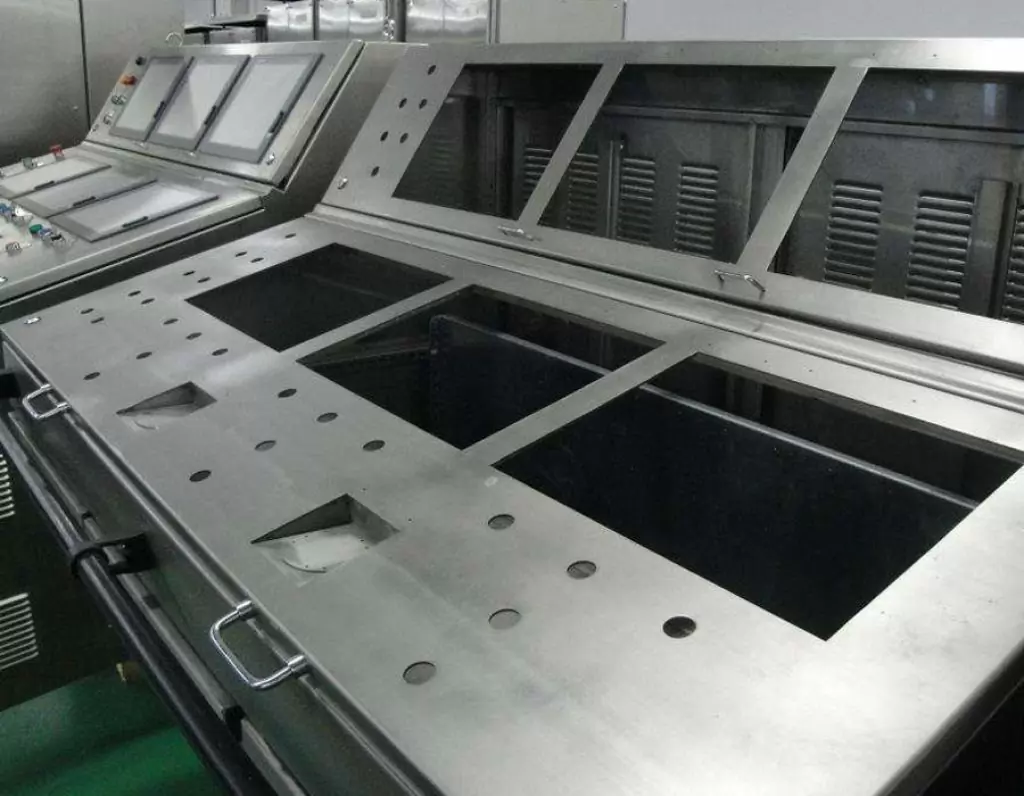
BE-CU is a professional and technical enterprise engaged in sheet metal fabrication, with over 2000 m2 sheet metal workshop and has one-stop service of industrial automation R&D, production, processing and sales.Custom manufacturer of sheet metal component assemblies made from stainless steel, aluminum and carbon steel. Offered in different specifications and features.Markets served include aerospace, lighting, medical, defense, semiconductor/electronics, capacitor, chemical processing and energy.Capable of maintaining dimensional tolerance up to +/-0.005 in. Capabilities include contract manufacturing, fabrication, machining, bending, milling, cutting, forming, drilling, fitting, assembly, notching, punching, rolling, turning, CNC press braking, flame and high definition plasma cutting, saw cutting, shearing, prototyping, high volume, short run and long run production and MIG, TIG and arc welding. Secondary services include Blanchard grinding, galvanizing and painting.
-
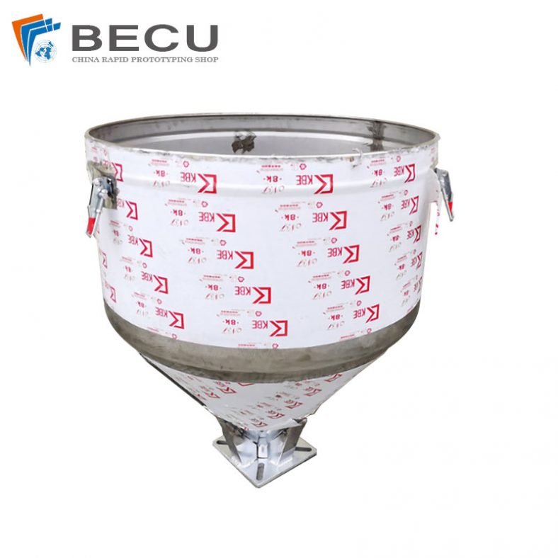
Sheet Metal Fabrication Injection Molding Machine Hopper
-
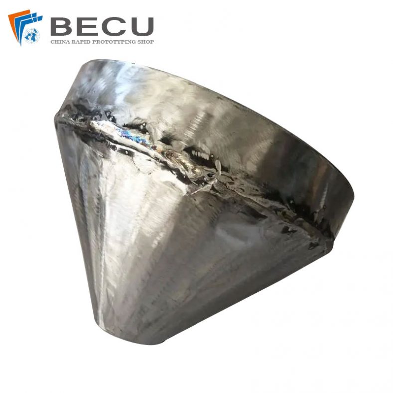
Sheet Metal Fabrication Funnel For Agricultural Machinery
-
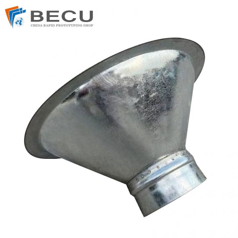
Sheet Metal Fabrication Galvanized Spiral Air Duct
-
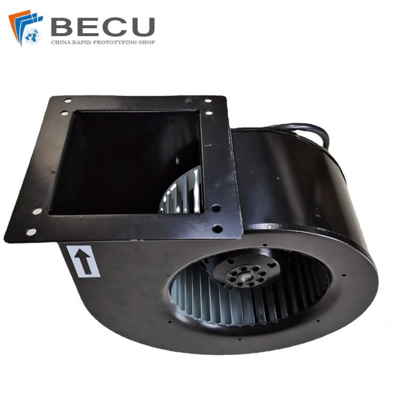
PCS Fan Ductwork Sheet Metal Housing
-
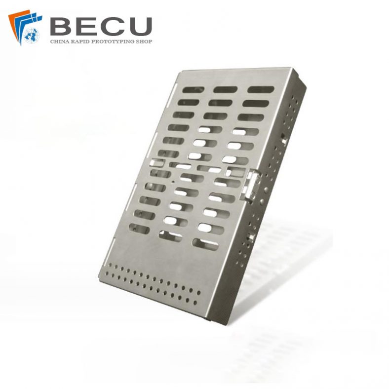
Custom Sheet Metal Surgical Instrument Sterilization Box For Beauty Salon
-
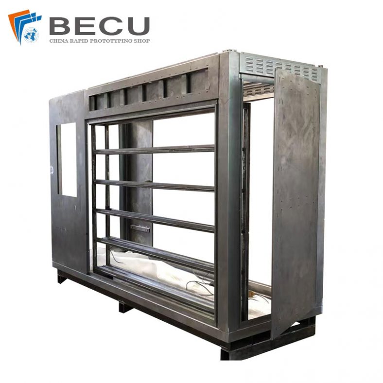
Precision Fabrication Green Energy EV Charging Station Cabinet
-
TA1TA2 Alloy Sheet Metal Manufacturing Machinery Support Parts
-
Sheet Metal Fabrication Aluminum 5052 Medical Box For Fire Fighting