
The five-axis machining process is briefly explained, and the working principle of key nodes is explained in detail. The homogeneous transformation method is used to model and solve the five-axis CAM tool position data and the motion of each axis of the post-processing machine tool. The method is simple and easy to understand. Five-coordinate CNC machining is an important means to achieve high-efficiency and high-quality machining of large and special-shaped complex parts. The five-coordinate machine tool can not only make the position of the tool relative to the workpiece arbitrarily controllable, but also the direction of the multi axis machining relative to the workpiece can be arbitrarily controllable within a certain range, so that the five-coordinate machining has the following characteristics:
- It can avoid tool interference, process complex parts that are difficult to process by ordinary three-coordinate machine tools, and have wide processing adaptability.
- For ruled surface parts, the side milling method can be used for one-cut forming, which has good processing quality and high efficiency.
- For general three-dimensional profiles, especially large flat surfaces, the end face of a large-diameter end mill can be processed close to the surface. The number of passes is small and the residual height is small, which can greatly improve the processing efficiency and surface quality.
The Introduction Of Five Axis CNC Machining
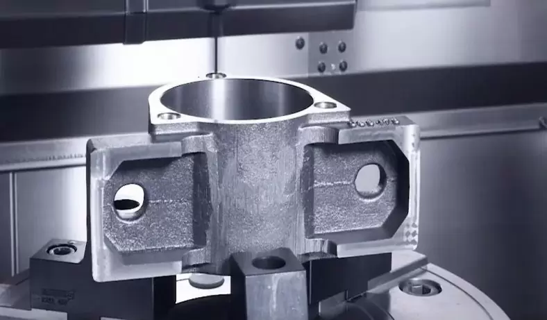
At present, more and more fields have increasingly higher design requirements for their products. In addition to traditional aerospace, automobile, ship and other fields, curved surfaces with large curvature are often used to achieve high aerodynamic performance. Also starting to use more and more freeform shapes. Traditional 3-axis machining can only process a surface with a single convex curve feature, and cannot do anything for surfaces with complex curve changes (deep concave or low-cut). At this time, 5 axis machining is required. In addition, for products with strict shape and dimensional tolerances, 5-axis one-time clamping can also be used for multi-face processing to avoid accuracy loss caused by multiple clamping.
Successful 5-axis machining depends on 4 factors that depend on each other to varying degrees:
- Machine tool (rigidity of bed structure, spindle stability, transmission system accuracy, etc.)
- Control hardware (motors, feedback components, drives, etc.)
- Control software (NC system motion, interpolation algorithm, etc.)
- Process programming software (tool path generation and post-processing)
The review states that in 5-axis machining, purely technical properties such as machine tools, control systems, tool holders, etc. are not the only factors that affect the final result, the quality of the result depends to a large extent on the design tools (especially CAM software) that support the entire process ) is used correctly. In this paper, the fourth point is explained in detail, and the 5-axis machining workflow and basic principles are briefly introduced. 1. Introduction to the five-axis machining workflow
As shown in Figure 1, the five-axis machining workflow is roughly as follows [1]:
1.Product 3D Design
According to the function and appearance requirements of the product, CAD design software is used for 3D design. CAD design software provides a variety of free-form surface modeling, including Coons surface, Bezier surface, B-spline surface, etc. In addition, 3D design software can generally be combined with finite element analysis. The software and CAM software are combined and connected to provide good support for product design optimization and subsequent processing and manufacturing. Commonly used CAD design software are: UG, Pro/E, SolidWorks, etc.
2.Tool Position File Generation
Input the 3D modeling file of the product, use the CAM software to set the tool type and parameters, process plan, tool axis control mode, tool path rules, etc., and calculate and generate the tool position file (this calculation process is called the main process of CAM). Commonly used CAM software are: UG, Pro/E, PowerMill, HyperMill, etc.
3.CNC Machining Program Generation
Input the tool position file, use the CAM software to set the characteristics of the machine tool and the CNC system, and calculate and generate the machining program (this calculation process is called CAM post-processing).
4.The Simulation Of Machining Program
With the help of the machine tool simulation environment (generally need to be built according to the specific machine tool), simulate the generated processing program to check whether the processing action is reasonable. Generally, only qualitative analysis can be performed in this step, and quantitative analysis such as specific processing effects needs to be verified by practical processing. Actual machining Copy the generated machining program into a specific machine tool and perform actual machining.
Homogeneous Coordinate Transformation
Four-dimensional homogeneous matrices are commonly used in mechanics, robotics and computer graphics to represent the coordinate transformation between two adjacent coordinate systems in three-dimensional space. In the subsequent description of the working principle, coordinate transformation is required in many places, so the secondary coordinate transformation is explained separately here.
As shown in Figure 2 below, O is the origin of the reference coordinate system, O’ is the origin of the moving coordinate system, and P(P’) represents the position vector of the tool center in the reference coordinate system (moving coordinate system) [Px, Py, Pz, 1]T ([P’x, P’y, P’z, 1]T), V(V’) represents the attitude vector [Vx, Vy, Vz, 0]T of the tool attitude in the reference coordinate system (moving coordinate system) ([V’x, V’y, V’z, 0]T). The moving coordinate system is the reference coordinate system rotated around X, Y, Z by angle A, B, C, and then translated [X, Y, Z]. The coordinate transformation expression is as follows [2]:
Among them, Rot(X, A), Rot(Y, B) and Rot(Z, C) represent the transformation matrices of rotation angles A, B, and C around the X, Y, and Z axes, respectively, and Trans(X, Y, Z) is Represents a transformation matrix translated along the vector [X, Y, Z]. For coordinate transformation between two coordinate systems, it is necessary to multiply the adjacent coordinate system transformation matrices together, and the sequence of matrix multiplication cannot be arbitrarily changed. If you want to calculate the change of the coordinates of the point in the moving coordinate system relative to the reference coordinate system, multiply the transformation matrix to the right; if you want to calculate the change of the point in the reference coordinate in the moving coordinate system, multiply the transformation matrix to the left.
Introduction To The Working Principle Of The CAM Main Processor
CAM main processor mainly completes tool path generation, tool interference inspection and tool axis orientation optimization, and generates tool position files. The working principle is shown in Figure 3. The principle of each working module of the CAM main processor is briefly introduced below.
1.The Calculation Of Tool Position Data
As shown in Figure 4, the tool coordinate system O is established with the tool center point O as the origin and the tool axis direction as the Z axis; the contact point between the tool and the workpiece surface is C, with C as the origin, the tangential direction of the curve as the X axis, the curve The normal direction establishes the local coordinate C for the Z axis; the workpiece defines the workpiece coordinate system W.
The tool location data calculation is to calculate the position vector PW and attitude vector VW of the tool center point O and the tool axis unit vector T in the workpiece coordinate system W. Since the tool coordinate system O and the workpiece coordinate system W are non-adjacent coordinate systems, they need to be connected by the local coordinate system C. The specific calculation expression is as follows:
They are the transformation matrices from the tool coordinate system O to the local coordinate system C, and the local coordinate system C to the workpiece coordinate system W, respectively.
2.The Calculation Of Cutting Step Length
At present, there are several common methods for calculating the cutting step length:
- Equal parameter discrete approximation method As shown in the figure below, the tool step length is calculated by inputting the equidistant parameter sequence.
- Step length estimation method According to the micro-geometry of the surface at the current tool contact point and the cutting direction, the discrete tool moving step length that meets the programming accuracy requirements is estimated, and then the position of the next tool contact point or tool position point is determined. The common method of step size estimation is to perform arc chord approximation to the theoretical tool path and tool contact point path, and to approximately determine the machining error and feed step size by the chord bow height error.
3.The Calculation Of Tool Distance
At present, there are several common methods for calculating the tool distance:
- Parametric line method As shown in the figure below, the tool path is generated by taking the parametric line of the machined surface as the tool contact point path. The algorithm is simple, the calculation amount is small, and it is suitable for the case where the surface parameter line is distributed evenly.
- CC path section line method As shown in the figure below, in the process of cutting the tool, the contact point (CC point) between the tool and the surface to be machined is always constrained to another set of surfaces, that is, a set of constraint surfaces and the surface to be machined are used. The intersection line is used as the tool contact point path to generate the tool path. The generated tool contact point trajectory is evenly distributed, which is suitable for surface processing, cavity processing and complex composite surface processing with uneven distribution of parameter lines. The intersection operation is required, the algorithm is complex, and the calculation amount is large.
- CL path section line method As shown in the figure below, the intersection line of a set of constraint surfaces and the tool offset surface of the machined surface is used as the tool path. There are two implementation algorithms: directly construct the tool offset surface of the part surface, and use the constraint surface Find the intersection between the surface and the offset surface; directly find a series of tool positions on the constraint surface where the tool is tangent to the surface to be processed through iteration and other measures. It is especially suitable for the machining of curved bottom pockets with boundary constraints and continuous machining of complex composite surfaces. .
- Driving surface method As shown in the figure below, the tool movement process is constrained by introducing a guiding surface, so that the tool is always kept tangent to the machined surface (part surface) and the guiding surface during the tool movement. The numerical iterative calculation of the algorithm is large, and there is a stability problem of whether the iteration converges. It is generally used for root cleaning of the intersection lines of combined surfaces.
Side milling cutter bar interference avoidance: axis translation method Side milling cutter head interference avoidance: axial movement method
Introduction To The Working Principle Of The CAM Post-Processor
The CAM post-processor reads the tool position file, and according to the characteristics of the machine tool and the numerical control system, completes the motion solution of the machine tool axis, the check and processing of the nonlinear motion error, the check and correction of the feed rate, and finally generates the numerical control machining program. The working principle is shown in Figure 6. The principle of each working module of the CAM post-processor is briefly introduced below.
There are three types of 5-axis machines:
1.Tool Axis Rotation Type, Table Rotation Type, Hybrid Type (1 Tool Axis Rotation + 1 Table Rotation)
According to the above-mentioned 5-axis machine tool type, generalize and abstract, build a unified motion model as shown in Figure 7, and solve the motion. According to the tool file, the position vector PW and attitude vector VW of the tool center point in the workpiece coordinate system WCS can be known. According to the above homogeneous transformation principle and the known machine tool characteristic parameters, the following equations can be derived. Axis position value [3].
2.Nonlinear Motion Error Checking And CNC Machining
As shown in the figure below, when each motion axis of the machine tool performs linear interpolation motion in each block, the combination of its motion will make the motion trajectory of the tool position point deviate from the straight line, which may cause the actual machining error to be too large, which is called Machine tool nonlinear motion machining error. Generally, it is checked according to the kinematic structure and size of the machine tool in the post-processing process, and the error checking process can only be approximate.
3.The Check And Correction Of Feed Speed
As shown in the figure below, check the composite feedrate of each block according to the speed, acceleration and stability of each axis of the machine tool, make necessary adjustments to the commanded feedrate, and take certain measures to realize the feedrate. The smooth transition of the speed can determine the effective feed speed curve that changes with the machining path.
4.NC Machining Program Generation
According to the characteristics of the numerical control system (mainly the programming rules), the calculated position value of each axis of the machine tool, the corrected speed value and other information are output to generate the numerical control machining program.
The Summary Of Five Axis CNC Machining
This paper describes the 5-axis machining workflow, and explains the working principles of key working nodes in detail, and comprehensively and clearly explains the knowledge of 5-axis machining. In addition, the method of homogeneous transformation is described in detail, and it is applied to the main processing and post-processing related calculations of 5-axis CAM.
-

AZ91D CNC Machining Quadcopter Arm Landing Gear
-
CNC Machining Lightweight Magnesium Alloy AZ91D Drone Gimbal Parts
-

CNC Machining Magnesium AZ61 Drone Blade Protection Cover
-

CNC Machining Magnesium AZ91D AI Ar Glasses Frame
-

CNC Machining AZ91D Magnesium Alloy High-End License Plate Frame
-

CNC Machining AZ91D Magnesium Alloy Laptop Middle Frame
-

CNC Machining AZ91D Magnesium Horizontal and Vertical Quick Turn Camera Stand
-

ZK61 Magnesium Cnc Machining Automation Parts