
What Is Automobile Grille
When portraying the shape of a car, the front of the car is the focus of interpreting the styling of the model, not only to emphasize the individual design of the lights, grille, bumper and other parts, but more importantly the coordination of the overall shape.
The grille is one of the most individual parts. Longer-established car manufacturers have developed their own unique car culture, and no matter how new models change, the style of the grille does not change easily.
For example, BMW features two large square frames, JEEP has seven square holes side by side, and Volkswagen has a long horizontal bar. Korea’s KIA Motors also began to develop its own iconic tiger head shape after tapping Volkswagen’s chief designer Peter Hillier (the first Audi TT designer and one of Europe’s top three car designers).
The Features And Requirements Of Automobile Grille
The front grille of a vehicle is a grid-like part of the front part of the vehicle with a grid. The front grille of the vehicle is located between the front bumper and the front cross member of the body. Since the hood lock needs to be arranged in the upper surface area of the front grille, the front grille needs to open hood lock avoidance holes to avoid the hood lock.
The Tpes Of Automobile Grille
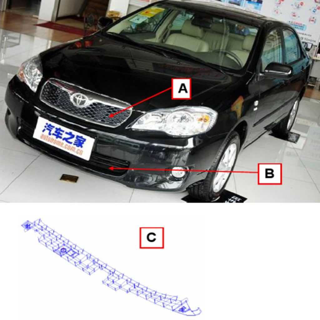
Grilles usually have three positions in automobiles:
- A) air intake grille (radiator grille);
- B) Bumper grille
- C) Buffer grille
In addition to the beauty of the front grille, the biggest role is to intake air and reduce air resistance. The greater the impact of the front grille on the resistance of the engine compartment, engine compartment resistance accounts for about 10% of the overall resistance, the grille active closure is conducive to reducing the resistance in the engine compartment.A and B are exterior parts that are common to all car models, so we will focus on them. C is a functional part that is not usually seen by users in the interior of the car, and not all car brands have such products, so we will not explain them in detail. The grille mentioned below refers to both A and B.
The Material Requirements For Automobile Grille
The automobile grille is an exterior part and has weather resistance requirements.
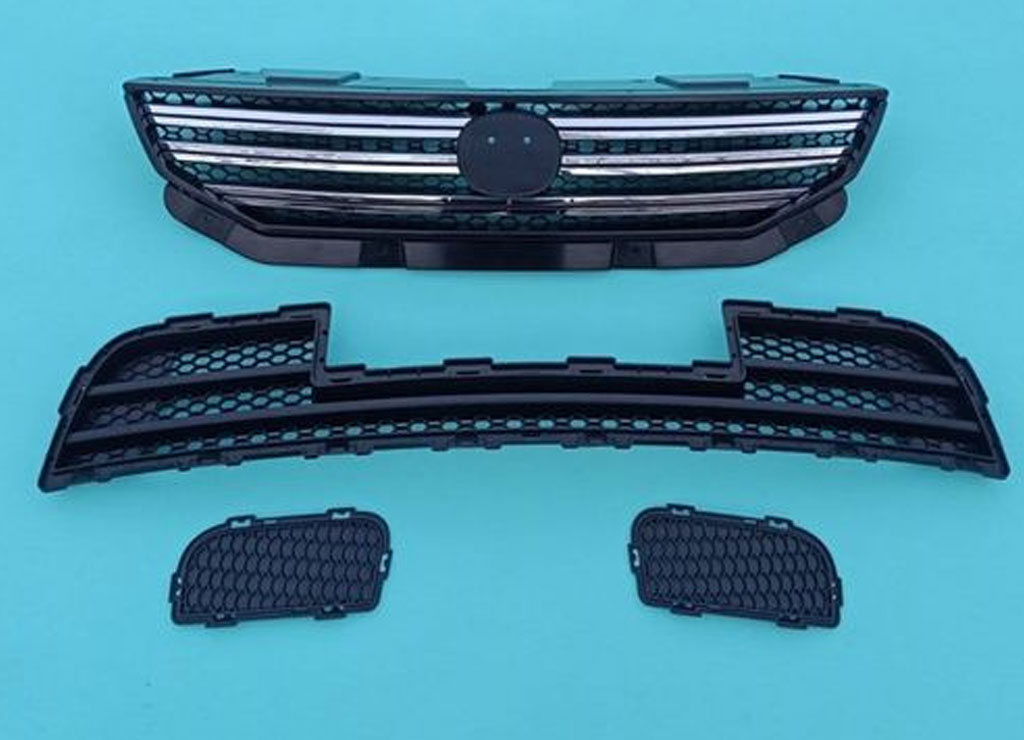
The surface treatment of air inlet grille is usually leather, sandblasting, painting, electroplating, and the materials are usually PP, ABS, ASA, etc.
The bumper grille has lower requirements, usually with leather pattern, sandblasting, and mainly PP material.
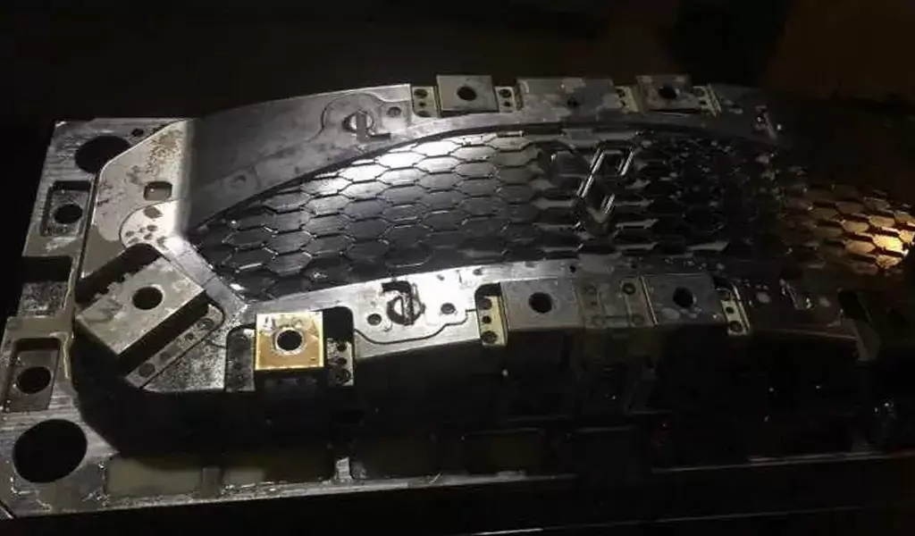
The grille is an exterior part with high surface quality requirements. Due to the limitation of product structure, it is difficult to eliminate the fusion marks. How to control the position of the fusion marks is the most important problem for these products.
The Structure Characteristics Of Automobile Grille
- The grids can be divided into irregular grids and square grids according to the shape of the mesh. The problem of fusion marks is more pronounced for square-hole grids, but it is easier to solve these problems in terms of mold construction.
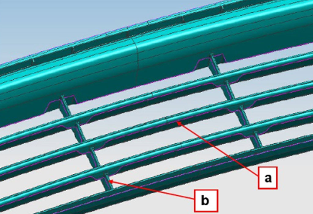
- The grid is usually different in two directions, one for the main body, position a, and the other for the secondary reinforcement, position b. The presence of fusion marks in the main direction is a concern, so fusion marks should be. The fusion marks are located in the secondary position.
The grid parting line is complex and the parting surface needs to be designed according to a certain rule, not arbitrarily, to avoid problems with the mold (detailed in the mold description section). The slope of the release at the product grid is usually not large, . Therefore, the design should be checked against the surface treatment requirements. If the product has a rib position in the front and rear mold, it is necessary to check the release slope of the front and rear mold, which is usually larger than the rear mold, to avoid the product staying in the front mold.
Preface
Automotive grille-type parts refer to the main structure of the product has more grid-like structure, the grid is perforated in the middle, for the grid structure only exists in the local structure of the parts, not included in this category. Such parts generally refer to:
1.Engine air intake grille (radiator grille);
2、Bumper trim grille;
3, the car’s interior cushion grille. For exterior grilles, the most important thing is the surface quality.
Because of its grid-like structure, the material flow is complicated and difficult to control, and melt marks are the main problem.
CNC Machining Requirements For Automotive Grille-Type Molds
- Fractal surface and piercing tabs as far as possible do not turn the angle cnc machining (pay attention to tool wear, choose a longer life tool cnc machining), steep straight penetration surface and other must turn the angle cnc machining should be first end mill milling a section of the benchmark before turning the angle to align.
- Spark pattern area can not light knife (pay special attention to the fine parts of the tool path control), must ensure that 0.2mm margin, and the tool path should be smooth, not directly equal to the height of the trace directly discharge machining.
- Pay attention to the convex and concave die benchmark edge and the position of the guide pillar hole is consistent, before finishing and then review a benchmark.
- 3 + 2 Axis or 5 axis cnc machining machines finishing tool and tool shank selected as short as possible to reduce the head error. The number of times the parting surface is turned should also be as few as possible.
- Corresponding to the concave mold components at the parting surface without boundaries should be left 0.03mm margin.
Grille class mold cavity is more complex, it is recommended that the first 16r0.8 or 8R1 overall 0.15MM equal height!
Base angle test do not forget!
D16R0.8 cutting parameters: speed 2000, feed 3000, depth of cut 0.3MM
D8R1 cutting parameters: speed 4000, feed 3000.
- D4R0.5 tool to leave 0.15MM margin clear angle cnc machining.
- D4R0.5 cutting parameters: speed 6000, feed 2000, depth of cut 0.12MM
- Maximum clamping 28MM, maximum effective 16MM

- D3R1.5 tool to leave 0.15MM margin clear angle processing
- D3R1.5 cutting parameters: speed 10000, feed 2000, depth of cut 0.12MM
- Maximum clamping 28MM, maximum effective 10MM
- 8r4 overall 0.08mm margin 3D offset finishing! Forming separate, no interface together, runners sealed!
- D8R4 cutting parameters: speed 9000, feed 3500, depth of cut 0.5MM
- D4R2 tool to leave 0.08MM margin with clear angle finishing toolpath processing, local V angle and other high-definition angle.
- D4R2 cutting parameters: speed 9000, feed 2200, depth of cut 0.15MM (maximum clamping 28MM, maximum effective 12MM)
- D2R1 tool to leave 0.08MM margin with clear angle finishing toolpath processing, local V angle and other high-definition angle.
- D2R1 cutting parameters: speed 12000, feed 1700, depth of cut 0.08MM (maximum clamping 28MM, maximum effective 8MM)
- Parting surface mouth and unbounded place, breakdown all processing out!To have a test to ensure the size!
- The middle of the large breakdown with R2 tool processing, milling is not in place where the angle of the pendulum joint.
- Too long knife path apart then try to choose at the molding!
- Parting surface periphery and molding finishing!
- Select D8R4 or D4R2 tool finishing
- Overall clear corner, parting surface penetration class sharp angle at least milling to r0.5, milling to r0.25 conditions!
- The final shape do not forget, isometric plate, pin hole platform light a knife. If there is a wear plate precision positioning benchmark do not forget to pull!
Injection Mold For Automobile Grille
- In the process of the existing injection mold from the nozzle outlet of the injection molding machine through the runner to the gate, due to the temperature reduction, part of the plastic will solidify, causing waste of raw materials, and the runner is easy to be blocked.
- Now there is a hot runner mold on the market, which can keep the temperature in the runner within a proper range to prevent plastic solidification. The hot runner mold mainly includes injection nozzle, nozzle, splitter plate and temperature control box used to control the temperature of the hot runner. Multiple sets of power transmission lines are connected to the temperature control box to provide energy to make the temperature of the hot runner moderate. In order to prevent damage to the power supply circuit caused by the mold with higher temperature, A protective shell is usually provided, and the power supply circuit passes through the protective shell, and the protective shell is fixed with the mold.
- However, in the existing hot runner mold, the temperature control box is directly fixed on the mold, which is easy to be damaged due to the high temperature of the mold during operation.
The Plastic Injection Mold Design For Automobile Grille
According to the structural characteristics and technical requirements of the automobile grille, Be-cu Prototype has designed a pair of injection mold for the customer, which uses the hot runner needle valve nozzle to feed, and solves the problem of reverse stripping and ejection of molded plastic parts through the inclined guide pillar+slider, inclined push block, secondary direct push block, mold lock and nitrogen spring The production practice has proved that the die structure design is reasonable, the action is stable and reliable, the mass production plastic parts have good molding quality, and good economic benefits have been achieved
1.The Characteristics Of Automobile Grille Structural
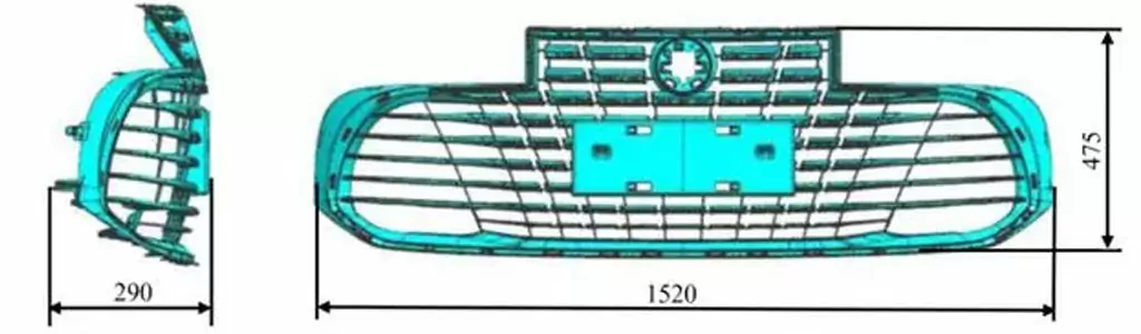
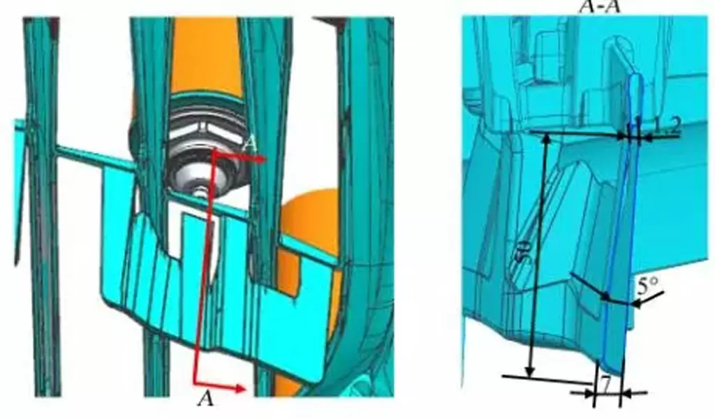
The overall dimension of car grille is 1520mm × 475mm × 290mm, as shown in Figure 1, no spot, gate trace, shrinkage depression, weld line, flash and other defects are allowed during molding. The grid is arranged in blocks. The strength of connecting bars between grids is weak. The grid bars are small, numerous and deep, up to 52mm deep. It is difficult to fill. In addition, there are many grid reverses, and the demoulding mechanism and the ejection mechanism are dense during mold design.
2.The Difficulties In Automobile Grille Mold Design
- Gating system design. Automobile grille is a kind of exterior part with high surface quality requirements. Due to its structure limitations, such as many grids and poor melt filling fluidity, it is critical to effectively control the position of weld lines through gating system design.
- Introduction of system design. In order to make the weld mark not on the appearance surface of the plastic part, the gate is set on the side of the straight push block, which increases the design difficulty of the push out system. The design of the ejection mechanism affects the molding quality of the plastic parts. If the design is not reasonable, it will lead to warping deformation, cracks, push rod marks and other defects of the molded plastic parts.
- Cooling system design. The large height drop of plastic parts, small, many and deep ribs, and high precision requirements lead to complex mold structure. How to effectively control the deformation of plastic parts through the cooling system is also the key point of mold design.
3.The Material Selection Of Grating
The grid is a kind of exterior part with weather resistance requirements. The surface treatment is paint spraying. The molding material is ABS (acrylonitrile (A) – butadiene (B) – styrene (S) terpolymer) with good performance. It integrates the performance of three components. Acrylonitrile has high hardness and strength, heat resistance and corrosion resistance, butadiene has impact resistance and toughness, and styrene has high surface luster, easy coloring and easy precision machining. The above characteristics make ABS plastic a “tough, tough, rigid” thermoplastic.
4.Mold Design Scheme
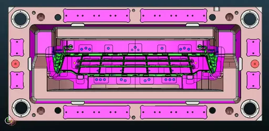
The mold adopts a hot runner gating system, 19 needle valve type hot nozzles are fed by a sequence valve, and the melt enters the cavity through a common runner gate in turn. There are 32 undercuts on the inner and outer surfaces of the plastic parts to be formed, and the sliding block and the inclined push block core pulling structure are used for demoulding. The overall dimension of the mold is 2230mm × 1600mm × 1265mm, with a total mass of 18600kg, is a large injection mold.
5.Mold Parting
Due to the large size and complex structure of the grid, based on its structural characteristics and materials, the mold adopts the layout of one mold and one cavity. When designing the parting surface, it is necessary to reduce and reduce the lapping of the upper and lower dies as much as possible to reduce the processing difficulty. The parting surface shall not produce flash, and shall be conducive to cavity exhaust.
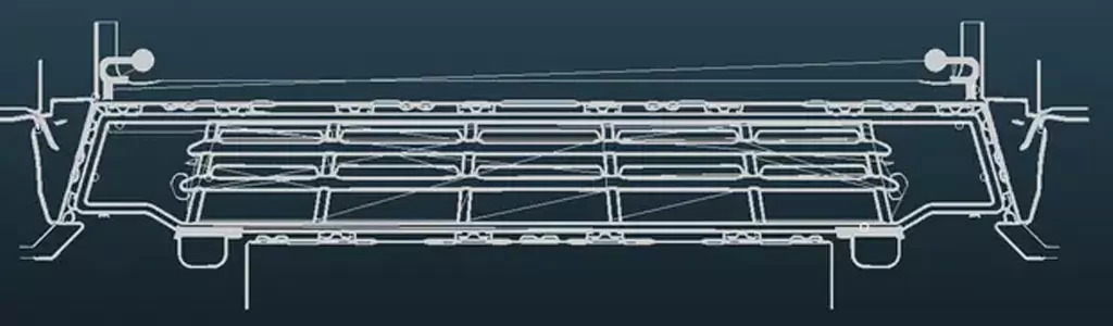
6.Pouring Scheme Design
The mold pouring system adopts “hot runner+common runner” for feeding, as shown in Figure 2. The hot runner system includes a hot runner plate and 19 needle valve type hot nozzles. The needle valve type hot nozzles are controlled by a sequence valve, which are opened in turn according to the shape and size of the plastic parts. The gate position should be arranged to make the material flow along the main direction, and move the weld line to the non appearance surface of the molded plastic parts.
The number of hot nozzles is large and dense. In order to prevent flashing of plastic parts, multiple support columns shall be designed on the hot runner splitter plate. When forming plastic parts, 9 gates are turned in from the side wall flow channel of the straight pushing block set between the block grids. The straight pushing block is designed to eject for the second time.
The second time is to eject the plastic part and the runner condensate together through the surrounding straight pushing blocks. Since the condensate of the runner needs to be forced to demould, the demoulding angle of the runner should be appropriate, and the R angle on the side of the runner should be large enough to prevent the plastic part from producing white pulling defects.
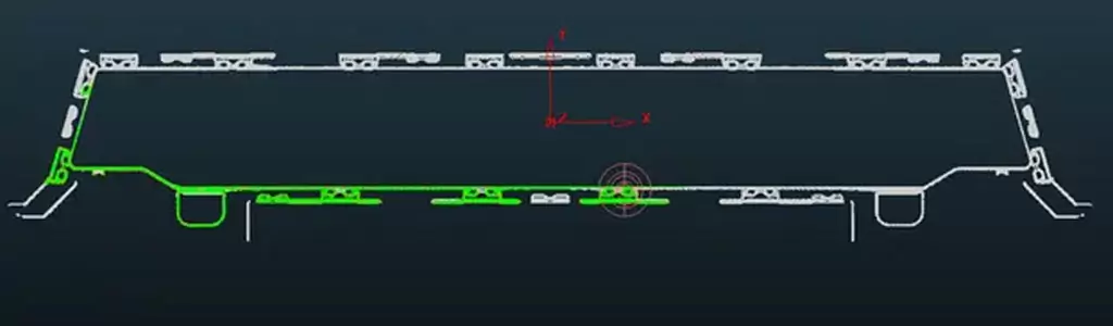
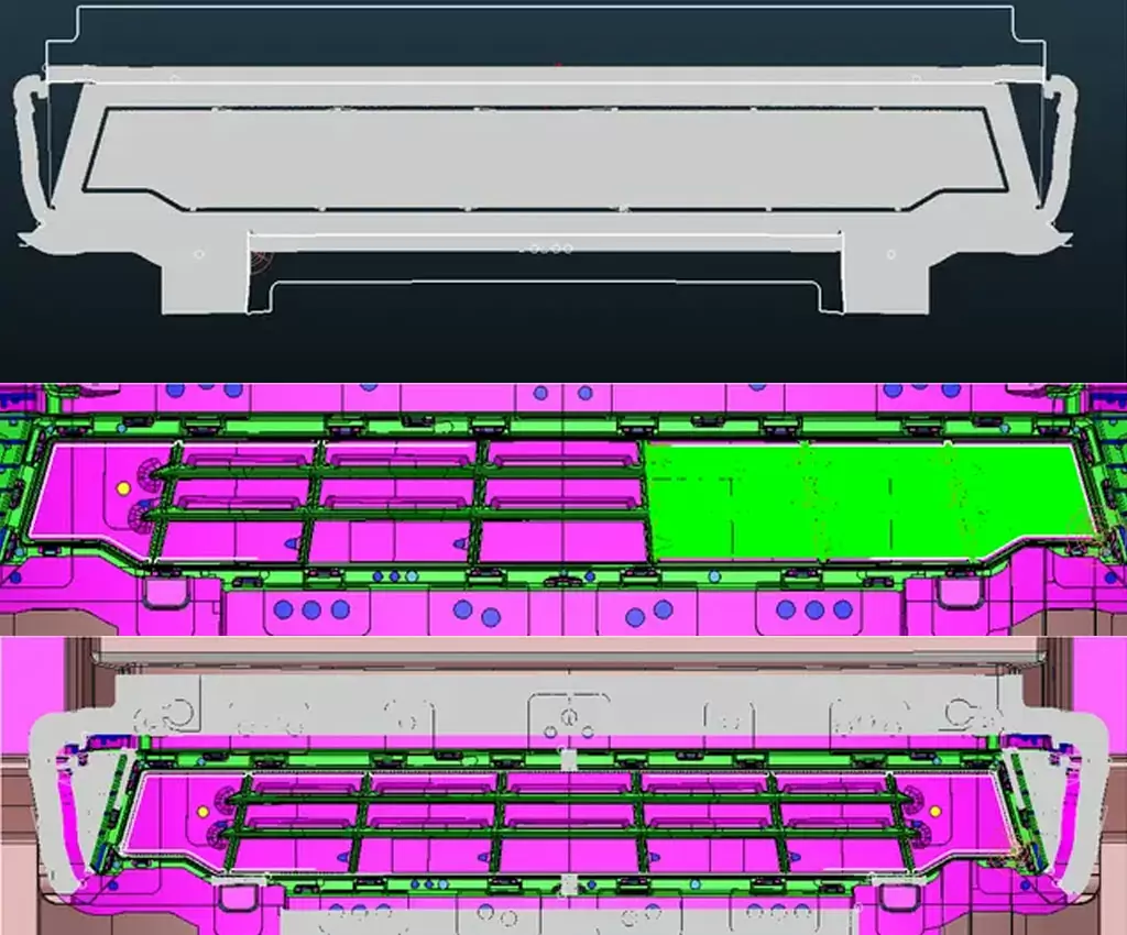
7.Cooling System Design
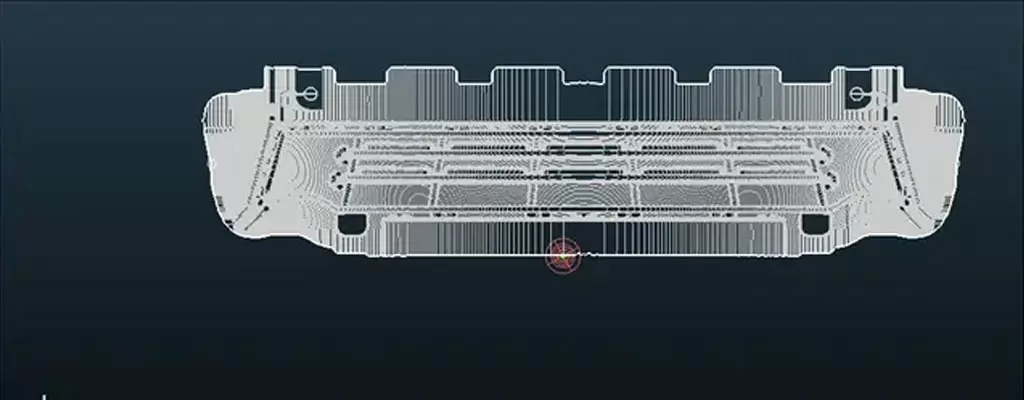
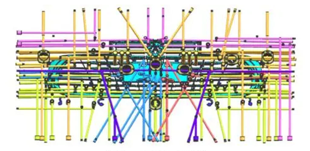
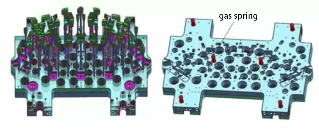
The design of the mold temperature control system has a great impact on the molding cycle and the molding quality of the plastic parts. One of the design principles of the cooling water path is that the distance between each part and the cavity wall is approximately equal, so as to achieve a roughly balanced temperature in each part of the cavity. The temperature control system of the mold adopts the combination form of “straight water pipe+inclined water pipe+water well”, which has the advantages of uniform cooling of plastic parts, short molding cycle, high molding quality, and is suitable for plastic parts with high requirements on appearance and performance. The local thin and high shape of the grid is formed by splicing structure, and is separately cooled by high thermal conductivity steel.
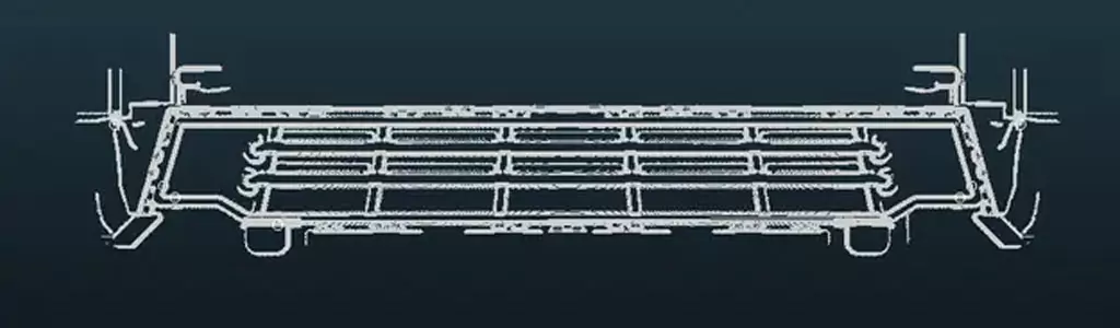
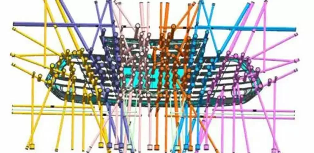
The upper and lower mold waterways shall be cooled sufficiently. The distance between each waterway and the cavity wall surface shall be similar. The length of each group of waterways shall be similar and the length of waterways shall not exceed 2m, as shown in Figure 3 and Figure 4. Double layer waterways or wells shall be designed in areas with large drop to achieve conformal cooling as far as possible. The inlet and outlet water temperature of the upper and lower mold shall be controlled within 5 ℃. The cooling water path is set separately at the hot nozzle, not in series with other water paths, which is conducive to heat dissipation in the hot nozzle area.
8.Demoulding Method
The grid backoff The grid backoff is located on the circumference, and the snap features simple structure and less backoff. According to the conditions, the sliding block and inclined push block can be used for demoulding.
9.Introduction System Design
The form of the ejection system is related to the shape, structure and plastic properties of the plastic parts. The ejection type, quantity and position are designed according to the ejection force and ejection resistance. The balance of pushing force ensures that the plastic parts are not deformed or damaged, and the pushing is smooth, stable and reliable. The die is pushed out by a push rod and a straight push block. The design difficulty lies in the pushing out of the upper runner condensate of the straight push block, the plastic assembly position and the special-shaped structure.
Pushing out of the upper runner of the push block
In order to avoid the appearance of the plastic part, runner and side gate are set on the side of the straight pushing block. The runner aggregate is similar to the shape of the undercut in the straight pushing block groove. The runner aggregate is pushed out from the lower mold by the large pushing block during the first push, and the plastic part and the runner aggregate are pushed out together by the small pushing block around during the second push. Since the runner aggregate needs to be forced to demould, a smooth transition surface needs to be designed for the undercut surface of the runner.
Push out of assembly position
There are many plastic parts for assembly. There are many plastic parts for assembly, with a height of 10~15mm. At the same time, the grid bars are connected by connecting bars. Therefore, because the grid bars are connected by connecting bars at each bone position, a push out mechanism needs to be set at each bone position, which not only facilitates the demoulding of plastic parts, but also improves the exhaust and reduces the filling pressure.
Ejection of profiled rubber level
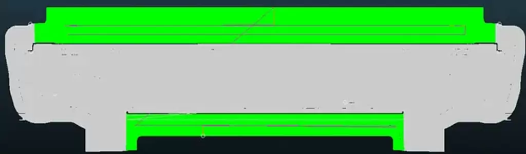
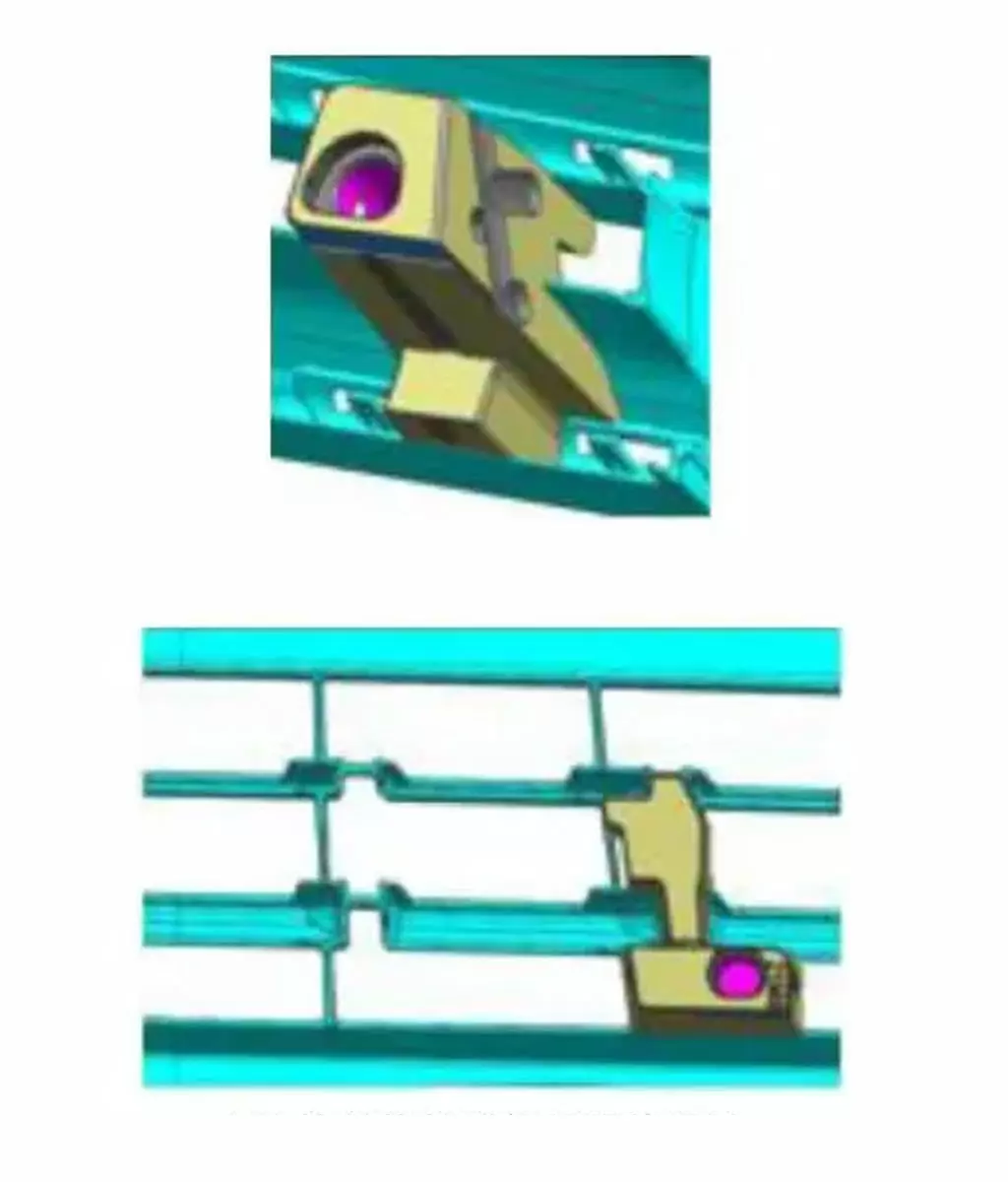
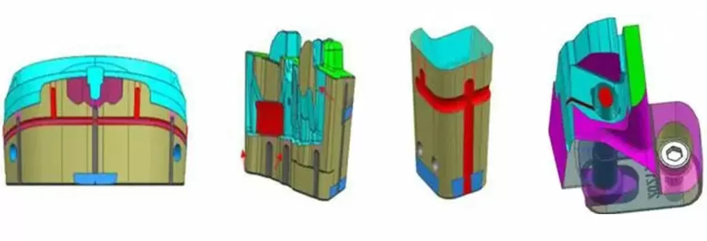
The profile glue plane is mainly the profile glue plane, which is mainly the deep bone position of the plastic part and the connection rib of the block grid. The two positions should design the straight push block based on the principle of the same direction of the side bread tightening force. The straight push block should be designed based on the principle of preventing the manipulator from grasping the direction after the plastic part is pushed out to prevent the manipulator from grasping the plastic part after it is pushed out, as shown in Figure 5.
10.Push Out Process
The mold adopts a secondary ejection mechanism, as shown in Figure 6. The drive mode is cylinder press+mold lock. The piston rod of the hydraulic cylinder directly drives the secondary pushing plate, and the primary pushing plate is driven by the mold lock. The primary pushing stroke is 80mm, and the side channel condensate on the straight pushing block is pushed out of the parting surface. The secondary pushing stroke is 50mm, and the channel condensate on the straight pushing block is forced to demould. The straight pushing block simultaneously pushes out the plastic parts.
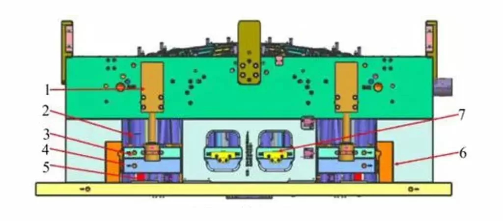
- Hydraulic cylinder
- Limit block
- Secondary push plate
- Primary push plate
- Nitrogen spring
- Pin type mold lock
- Wheel type mold lock
Due to the large length and size of the mold and the large spacing between hydraulic cylinders, the first block is equipped with a secondary push block, while the flow channel condensate on the primary direct push block is in the form of reverse thread. Due to the hardness and brittleness of ABS, the following two points should be noted during the push out process: ① The mold is designed with four sets of special clamping wheel type mold locks), four sets of pin type mold locks and six nitrogen springs, as shown in Figure 7, to ensure that the first push out mechanism and the second push out mechanism are the same as four sets) As shown in Figure 7, the pin type mold lock (4 sets) and nitrogen spring (6 pieces) ensure that the first and second push out mechanisms are synchronized, prevent the second push out from being higher than the first push out, and prevent the plastic parts from having push out defects; ② The layout of the die ejection mechanism is dense, so it is necessary to ensure that the ejector plate has sufficient strength to prevent plastic deformation during the ejection process.
11.Exhaust Slot Design
The function of the exhaust slot as the exhaust slot is to discharge the air in the mold cavity and various gases generated during the heating process of the plastic when injecting the molten plastic. The exhaust slot shall be designed to prevent the molten plastic from overflowing into the slot to block the exhaust. The exhaust slot can be set at the parting surface, the end of the material flow, the push rod, the insert pin and the insert.
U-shaped gas collecting groove with width of 8mm and depth of 1mm is designed on the parting surface of the mold, and 0.015-0.02mm deep exhaust groove is opened at 5mm from the mold cavity. The parting surface of each grid grid is provided with an air escape+exhaust slot, and the gas is discharged from the exhaust hole. The air trapping parts of the non parting surface, such as inserts, push blocks, runner push blocks and insert pins, need to be provided with exhaust grooves, as shown in Figure 8.
Mold Working Process
- Injections. The melt enters the mold cavity (2 points) through the hot runner; The melt enters the common runner through the hot runner and then enters the mold cavity through the side gate (8 points); The melt enters the runner in the direct pushing block of the lower mold from the upper mold through the hot runner, then enters the runner in the direct pushing block of the lower mold from the side gate, and then enters the mold cavity (9 points) from the side gate. After filling the cavity, the melt is kept under pressure, cooled and solidified.
- Open the mold. Under the action of the injection molding machine, the mold leaves the lower mold from the parting surface.
- Roll out. The nitrogen spring and the piston rod of the hydraulic cylinder directly drive the secondary push plate, and the primary push plate moves 80mm through the mold lock to push the condensate in the side channel on the straight push block out of the parting surface. The condensate in the side channel on the straight push block of the hydraulic cylinder piston pushes out the parting surface. The piston rod of the hydraulic cylinder continues to push out for 50mm, and the condensate in the inner channel of the straight pushing block is forced to demould. At the same time, the plastic parts are pushed out together, and the manipulator takes the parts.
- Mold closing. The secondary ejection mechanism and the primary ejection mechanism are closed, waiting for the next injection cycle.