
In order to ensure product quality and production efficiency, it is necessary to optimize the product structure and redesign the mold structure, and ensure the accuracy of processing and assembly and parts, in order to achieve the goals of product quality and quantity and reducing manufacturing costs.
Description Of Integrated Small Hole Punching Die
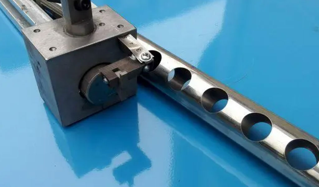
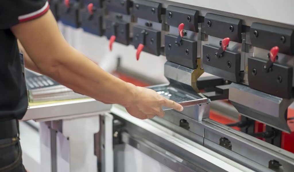
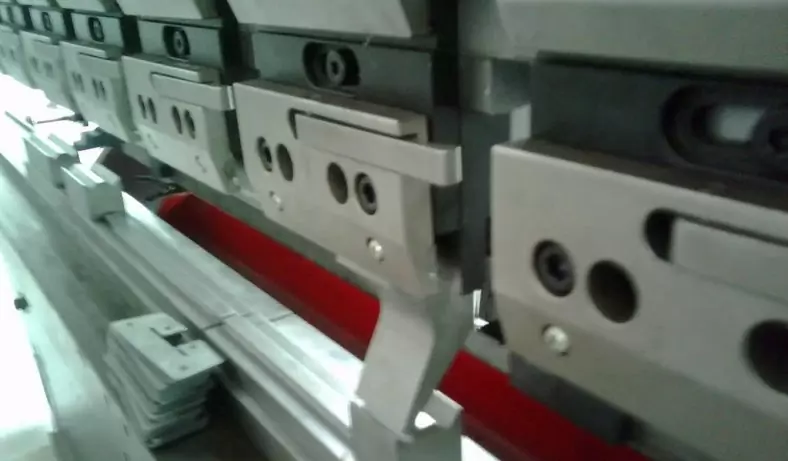
The blanking die is shown in Figure 1 and Figure 2. The description is as follows: Optimize the small holes of the product and reduce the types. The diameter of the punch ⑩ D≥2.5T is suitable (T=material thickness).
Add the small guide post ⑾ of the stripper plate to improve the guiding accuracy; the length of the small hole punching needle ⑩ is shortened from 60mm to 24.5mm; the punching insert of the lower die is made into a double-layer block, and the first layer of inserts ⑭
The thickness is 10mm, the material is SKH-9, the back side is left 2mm straight, and the whole body is discharged and hollowed out to prevent the needle from breaking due to blockage.
The second layer of inserts ⑮The thickness of 15mm is made of D2 material; the screw ②quick release device is locked and placed on the machine. It is easy to replace; all the small holes should be in the same step as far as possible, centralized punching, centralized waste suction, and increased waste suction equipment.
Structure Specific Implementation Plan
The small hole is concentrated in the punching step, and the stripper plate ⑤ is made into a double-layer structure ⑧ and ⑨.
According to the position of the corresponding hole on the product tape, the punching needle fixing plate ⑧ is cut on the line, and the punching needle ⑩ is fixed on the punching needle. In the wire cutting hole of the fixing plate ⑧, punch through the punching needle stripping plate ⑨. ;
When the punching needle is broken and needs to be replaced, first loosen the anti-locking screw ②, take out the punching needle stripping plate ⑨, then loosen the equal-height screw ①, take out the punching needle backing plate ⑦ and the punching needle fixing plate ⑧, so as to avoid dismantling the whole set The die can be replaced on the punch press.
The punching needle ⑩ is mounted on the punching needle fixing plate ⑧, and the punching needle backing plate ⑦ and the punching needle fixing plate ⑧ are fixed by small screws ⑫, which play the role of fixing and resisting the punching needle ⑩, preventing the punching needle from retreating during the punching process; Therefore, both the punching backing plate ⑦ and the punching needle fixing plate ⑧ need heat treatment. In order to ensure the smooth disassembly and assembly of the punching needle backing plate ⑦ and the punching needle fixing plate ⑧, the corresponding position of the stop plate ④ needs to make way through holes. This structure is also separate The precision small guide post ⑪ is used to guide up and down. The precision small guide post ⑾ is also mounted on the punching pin fixing plate ⑧, and passes through the punching pin stripping plate ⑨ into the guide post guide hole ⑬ of the lower die, so as to improve the guiding accuracy of the structure [2].
When the upper and lower dies are separated, the stripper plate ⑤, the stop plate ④ and the punching needle stripping plate ⑨ will be separated with the ejection of the spring assembly ⑥, while the punching needle backing plate ⑦ and the punching needle fixing plate ⑧ ①Fixed on the fixing plate ③, the punching needle ⑩ fixed on the punching needle fixing plate ⑧ returns to the punching needle stripping plate ⑨, so as to achieve the purpose of stripping after punching.
When the upper and lower dies are closed, the small precision guide post ⑾ will first enter the lower die together with other guide components, the die will continue to descend, and the punching needle ⑩ will pass through the punching needle stripper plate ⑨ and press the material before punching.
Design Improvement Of Small Hole Punching Die
Question Raising
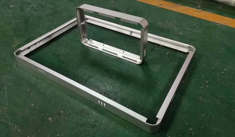
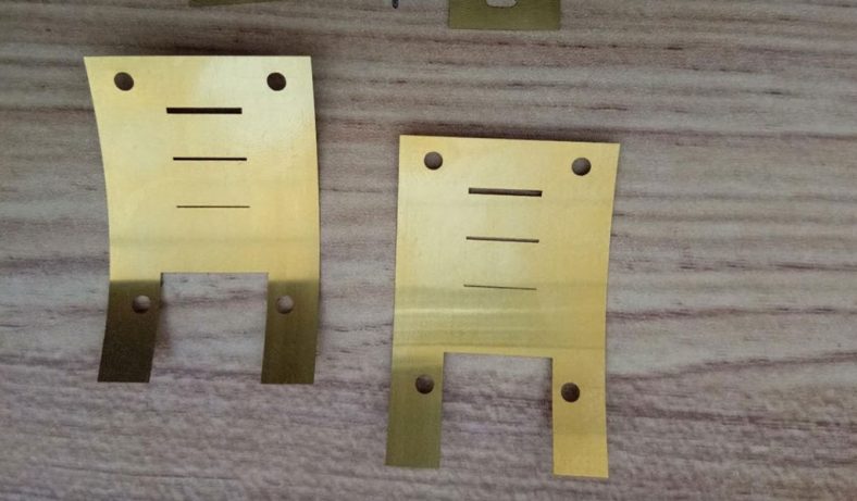
The stamped parts are shown in Figure 1. The material is 25CrMoVA and the thickness is 4mm. The following problems exist during mold trial and use:
- The hole spacing of 30±0.08 is often out of tolerance.
- There are burrs and serious tears on one side of the product appearance.
- The punching punch is easy to break and the mold life is short.
During the mold trial, it is difficult to ensure that the hole spacing is 30±0.08. Even if the trial mold is qualified, the life of the mold is only 200-300 pieces. Either the hole spacing is out of tolerance, or the punch is broken.
Reason analysis
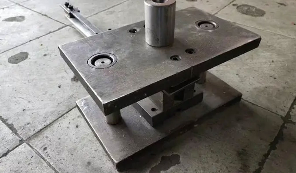
The mold structure is shown in Figure 2. There are many factors that affect the quality of the mold, and they involve a wide range of areas.
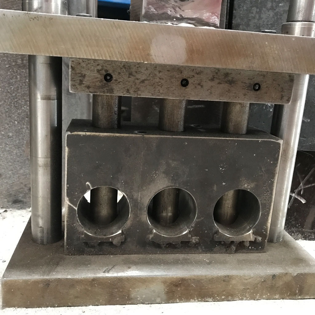
In order to solve the existing problems of the mold, it is necessary to go through multiple mold trials, and then analyze and improve them one by one based on the mold trial results. The main factors affecting the quality of the mold are the design and manufacturing quality of the mold. The material and heat treatment of the mold also have a certain impact on the quality of the mold.
- Driving rod;
- Push plate;
- Punch plywood;
- Concave mold;
- Positioning pin;
- Convex and concave mold;
- Concave and concave mold splints
- Upper template;
- Push rod;
- Unloading ring;
- Punch;
- Unloading plate;
- Rubber;
- Lower template;
Analysis of the causes of hole spacing out of tolerance
The reason for the excessive hole spacing can be found in the manufacturing and design of the mold. Manufacturing: Check whether the position of the hole on the punch clamp plate that matches the punch is out of tolerance, and check whether the assembled punch punch is perpendicular to the end face of the punch clamp plate. Design aspect: Check whether the punch is strong enough and whether it is protected during punching.
After actual measurement of the corresponding holes on the punch clamp plate and the distance between the two punches after assembly, the dimensions meet the drawing requirements, and it also shows that there is no problem with the perpendicularity between the punch and the clamp plate. At this time, we noticed that the working end of the punching punch was too slender and had poor rigidity. It may deform during operation, which may cause the hole spacing to exceed the tolerance. Therefore, the original punch structure must be improved.
Analysis of the reasons why there are burrs and serious tears on one side of the product appearance
For the punching die, the punching gap is the main factor affecting the cross-section quality of the part. If the gap is too large or too small, burrs will be produced, but the form is different. If the die gap is too small, a secondary bright band will appear on the punching section. Between the two bright bands There are tear bands in between, or intermittent small spots. The die gap is too large, the bright strip on the punched section is narrow, the tear zone has a large slope, and the burrs on the punched section are also large. When the mold gap is uneven, burrs will appear at unreasonable gaps and the cross-section quality will be poor.
The size of the punching overlap value will also affect the cross-section quality of the blanked parts. If the overlap value is too small, the normal stress acting on the side surface of the punch will be unevenly distributed along the cutting edge, which will not only reduce the cross-section of the punched parts.
The quality also reduces the life of the mold, so the minimum width of the overlap must be greater than the width of the plastic deformation zone during punching. Otherwise, the overlap may be deformed or broken during punching, and sometimes it may be pulled into the mold gap, causing parts to Burrs may even damage the mold edge.
Only one side of this part has burrs and severe tearing. Based on experience, it can be initially determined that the gap is biased to one side. But when the mold was opened and inspected, it was found that the gaps between the male and female molds on both sides were 0.4mm, which was even. At this time, we noticed that the overlap of the punched parts is 2.5mm. It may be that the overlap is a bit small, which causes the product to always have burrs and serious tears on the same side. The punching overlap should be appropriately increased.
Punching punch life is short
After the mold trial passes, the punching punch often breaks after two to three hundred or even dozens of parts have been made. There are many reasons for the short life of the punching punch, including the following: unreasonable punching clearance, structural defects of the punch itself, and partial unreasonable mold structure, all of which can cause the punch to fail prematurely. Figure 1 shows that the ratio of the material thickness to the hole diameter of the part is less than 1.5, which is a small hole punching and the stamping process is not good.
In addition, from a manufacturing perspective, the mold is limited by processing errors and assembly accuracy. The punch cannot be absolutely perpendicular to the plane of the concave mold, and the gaps will not be absolutely evenly distributed. Combining these two points, when the punch is relatively slender, Mold punch materials that are more likely to break are generally T8, Cr12Mo, and sometimes some imported materials are used. In terms of heat treatment, if the quenching hardness is too high, the punch will be more likely to break. If the quenching hardness is too low, the strength and rigidity of the punch will be poor, and it will easily become unstable and deformed, and the hole will not be punched through. The mold test results show that by replacing different materials and adjusting different quenching hardnesses, the life of the punch is slightly improved, but the effect is not obvious.
The Solutions Of Small Hole Punching Die
Changes in punch structure
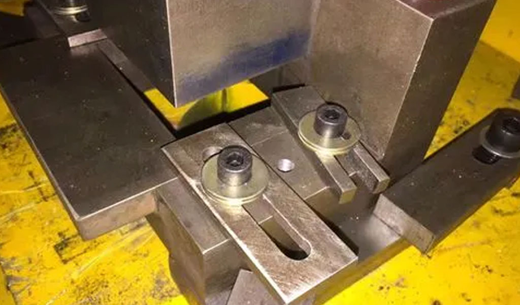
In order to increase the strength of the punch, improve the life of the punch and ensure the hole spacing of 30±0.08mm, the punch structure has been improved. As shown in Figure 3 and Figure 4. Figure 3 shows the standard punch given on the design drawing. The lower section is the working part, and the middle section is the press-fitting part with the plywood. Figure 4 is (continued from page 14) (continued from page 11) the improved structure, with a transition section added in the middle and the working part as short as possible to improve the strength and rigidity of the punch. The thickness of the punching punch stop plate is also increased to prevent the punch from being pulled out of the splint. The recess of the punching punch stop was also changed to R1.5 to prevent heat treatment stress concentration and cracks.
Adjustment of punch punch clearance
Using different blanking clearances for blanking and punching, the blanking clearance of the mold remains unchanged at 0.75mm~0.8mm, and the punching clearance is increased. The clearance between the punching die and the punch is about 30% larger than the blanking clearance, that is, 0.9mm~1.0mm. On the premise of ensuring the cross-section quality, appropriately increasing the punching gap can effectively reduce the punching force and indirectly increase the life of the punch, so the life of the mold will also be increased accordingly.
The large clearance fit between the punching punch and the unloading ring is changed to a small clearance sliding fit
Change the size of the hole on the unloading ring that matches the punching punch from a gap of 0.06mm to 0.08mm to a gap of 0.02mm. This can limit and guide the working punch to ensure the correct hole spacing. At the same time, after the gap is reduced, it protects the punching punch and makes the punch less likely to break.
The punching punch and the plywood are changed from interference fit to clearance fit
Since the gap between the working part of the punch and the unloading ring is only 0.02mm, and the punch will be deformed during operation, in order to prevent damage to the punch due to local over-positioning due to deformation, the matching part of the punch and the punch clamping plate is Change from interference fit to 0.02mm clearance fit. Another advantage of changing to clearance fit is that during assembly, you only need to gently push the punch into the punch plywood to prevent the punch from being perpendicular to the plywood by forcefully pressing the punch into the plywood during interference fit. occur.
The fit between the unloading ring and the die is changed to a small gap sliding fit.
The matching gap between the unloading ring and the die is changed from 0.06mm to 0.08mm to 0.02mm, which makes the unloading ring move smoothly and effectively protects the punch.
Change the punching edge size
The size of the punching overlap is increased, that is, the overlap is changed from 2.5mm to 4.5mm, which solves the problem of burrs and serious tears on one side of the product. After many mold trials and many improvements, various problems have been well solved, and the mold life has been increased from more than 200 pieces to more than 20,000 pieces, solving the urgent need for production. When similar problems occur in other stamped parts, we can also learn from the above methods and measures. For small hole punching, when the ratio of material thickness to hole diameter is less than 1.5, the stamping process will be poor and the punch will easily break. The following aspects should be paid attention to when designing:
- For small hole punching, the gap between the small hole die and punch should be about 30℅ larger than the normal punching gap.
- The working part of the punch should be shortened as much as possible, and the strength of the punching punch should be increased as much as possible.
- The punching punch and the plywood are changed from interference fit to sliding fit.
- The gap between the punching punch and the unloading plate is changed from a large gap to a small gap to protect the punch.
- The concave mold and the unloading ring are changed to a small gap sliding fit.
- Special attention should also be paid to the material selection and heat treatment of the punching punch.
Conclusion
To sum up, through verification, the length of the punching needle is shortened, from the conventional punching needle length of 60-65mm to 24-28mm, which increases the strength and life of the punching needle, and reduces the maintenance frequency and punching cost by more than 50%.
The structure concentrates the small holes in one step, and is designed as a quick-release structure, which saves the time of replacing the punching needle without disassembling the whole set of molds. The quality and quantity are guaranteed, the operation is simple, and the practicability is very strong.
China Sheet Metal Fabrication Company
Sheet fabrication services for mild steel, high strength low alloy (HSLA) steel, cold/hot rolled steel, galvanized steel, stainless steel, aluminum, copper and brass. Capable of fabricating parts up to 12 ft. length and +/-0.001 in. tolerance. Various capabilities include contract manufacturing,custom stamping,edge rolling, forming,top laser cutting, roll bending and welding. Finishing and secondary services such as hardware installation, tapping, deburring, cleaning, heat treating, plating, anodizing and painting available. Sheet Metal Prototype and low to high volume production runs offered.
Suitable for commercial/residential architectural, aluminum brake shape parts, wall panel systems, brackets, general flashings, rails, call button plates and ship building component parts.If you want a specific material to be used in the sheet metal fabrication process, don’t hesitate to contact us!
-
Stainless Steel Sheet Metal Fabrication
-
Aluminum Sheet Metal Fabrication
-
Copper Sheet Metal Fabrication
-
Brass Sheet Metal Fabrication
-
Steel Sheet Metal Fabrication
-
Titanium Sheet Metal Fabrication
-
Galvanized Steel Sheet Metal Fabrication
-
Mild Steel Sheet Metal Fabrication
-
Bronze Sheet Metal Fabrication
Our Sheet Metal Fabrication Applications
Be-Cu prototype offers custom sheet metal fabrication for creating structures, machines, and parts that includes:
Our Case Studies Gallery Of Sheet Metal Fabrication Parts
If you need custom Sheet Metal Fabrication parts in China from a trusted supplier, look no further. Professional service from 10 to 100000+ parts,Whether you want a small series production or large quantities,Be-Cu Prototype scale precision Sheet Metal Fabrication services according to our customers needs, including pipe,plate and tube cutting. Contact us to see how we can help you! Get a quote today!
-
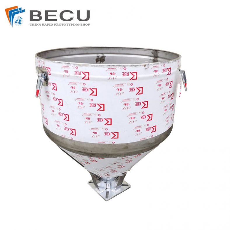
Sheet Metal Fabrication Injection Molding Machine Hopper
-
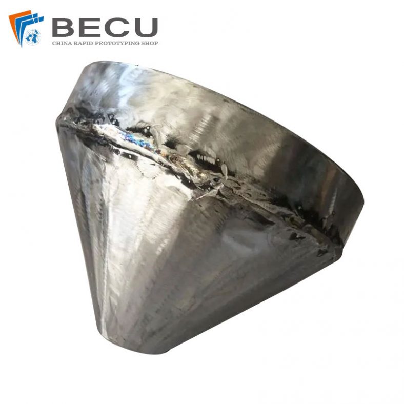
Sheet Metal Fabrication Funnel For Agricultural Machinery
-
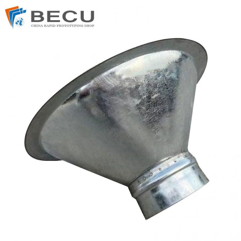
Sheet Metal Fabrication Galvanized Spiral Air Duct
-
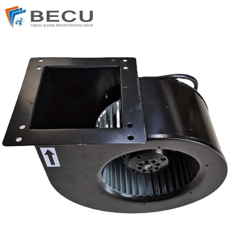
PCS Fan Ductwork Sheet Metal Housing
-
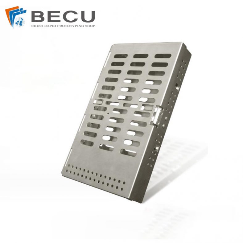
Custom Sheet Metal Surgical Instrument Sterilization Box For Beauty Salon
-

Precision Fabrication Green Energy EV Charging Station Cabinet
-
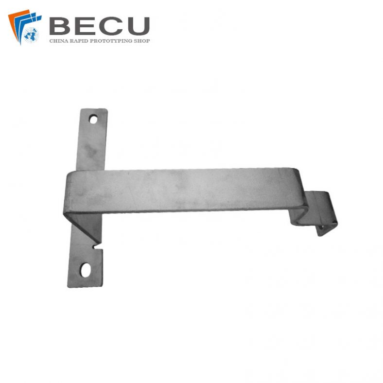
TA1TA2 Alloy Sheet Metal Manufacturing Machinery Support Parts
-
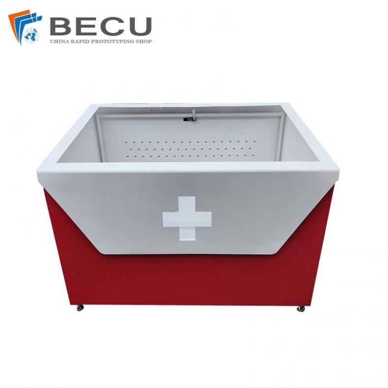
Sheet Metal Fabrication Aluminum 5052 Medical Box For Fire Fighting