
In manufacturing processes such as injection moulding,vacuum forming, forging, and casting, calculate daft angle is paramount to the quality and efficiency of the produced parts.The draft angle, also referred to simply as “draft,” is an angle applied to the vertical walls of a part to facilitate its removal from a mold. Without an appropriate draft angle, parts may stick or become damaged during the demolding process, leading to increased production costs and time.
What Is Draft Angle
The draft angle, also known as demolding angle, is a slope designed on both sides of a mold cavity to facilitate easy removal of the molded part.
The orientation of the draft angle depends on the internal and external dimensions of the plastic part. To ensure smooth ejection from the mold, draft angles must be set on surfaces (including side cores and ribs) that move in the same direction as the mold opening and closing.
The size of the draft angle for plastic parts is influenced by their properties, shrinkage rate, friction coefficient, wall thickness, and geometric shape. Hard plastics require larger draft angles compared to soft plastics. Parts with complex shapes or multiple molding holes typically require larger draft angles.
Parts with greater height or deeper holes require smaller draft angles. Moreover, thicker walls or tight fits around internal cores necessitate larger draft angles. Sometimes, draft angles are intentionally reduced or increased on specific edges to ensure that parts remain in the cavity or on the core during mold opening.
In addition, both male and female molds, as well as inserts and slides, require draft angles. Typically, the minimum draft angle is 5°, but it is generally recommended to use 7° or more. The direction of the draft angle should align with the direction in which the mold’s ejector pins push or the direction of cylinder action on the machine. This is especially crucial when there are textures on the mold surface.
Principles Of Draft Angle
During part cooling, it shrinks towards the core. Draft angles help parts avoid interference with the core. Even if there is a consideration to eliminate draft angles, they should never be completely removed. Reducing draft angles increases the locking force on the part, thereby requiring more force to remove the part from the mold. This extends the mold cycle time to ensure sufficient cooling for easy removal without deformation, typically occupying 50% to 80% of the entire molding cycle. Conversely, larger draft angles reduce the force needed for part removal, resulting in shorter ejection times.
Considering these conflicting factors, for most fill materials, a balanced approach involves reducing draft angles to approximately 1°. However, the habitual use of 1° for all situations overlooks potential cost savings achievable with appropriate draft angles.
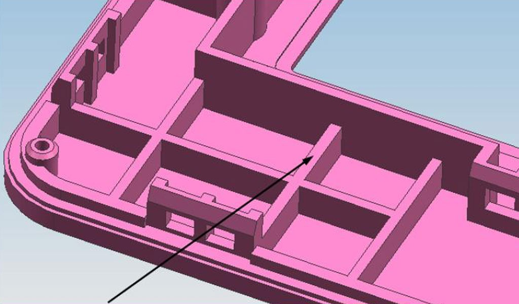
Locking force increases with the use of ribs, which create additional constraints on the part surface. The situation worsens with multiple ribs, although it is preferable to having no draft angle or using thick ribs with high internal stress. Figure 1 illustrates the minimum spacing between ribs, which is twice the nominal wall thickness. External ribs on the part wall allow gases inside the mold cavity to escape through rib cavities, whereas integral ribs can trap gases within the part.
Designing Draft Angles draft For Plastic and Metal
Draft angles are typically adjusted on the reference model to facilitate part removal from the mold after cooling-induced shrinkage, preventing parts from tightly adhering to mold cavities or sand cores. Failure to implement proper draft angles or their absence can increase demolding resistance, scratch part surfaces, and potentially deform parts, affecting their quality. Draft angles depend on part geometry, shrinkage rate, and material properties. If parts remain on sand cores during demolding, internal surface draft angles should exceed those on external surfaces. Longer demolding directions require smaller draft angles, and vice versa.
To accommodate allowances for part repair, larger dimensions are ensured at the major end for shaft-like parts, while smaller dimensions are maintained at the minor end for hole-like parts.
Height and Draft Angles
Larger draft angles ease demolding, which is crucial for products with deeper walls or greater heights. Calculating thickness variations due to draft angles in advance helps prevent issues arising from excessively thin or thick wall sections during molding:
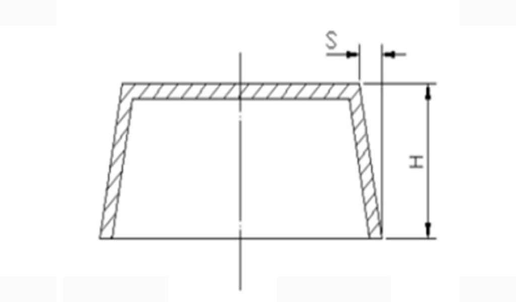
tanθ = X / H; where θ = draft angle, H = wall or rib height, X = reduced wall thickness (or tilt deviation).
BE-CU.COM
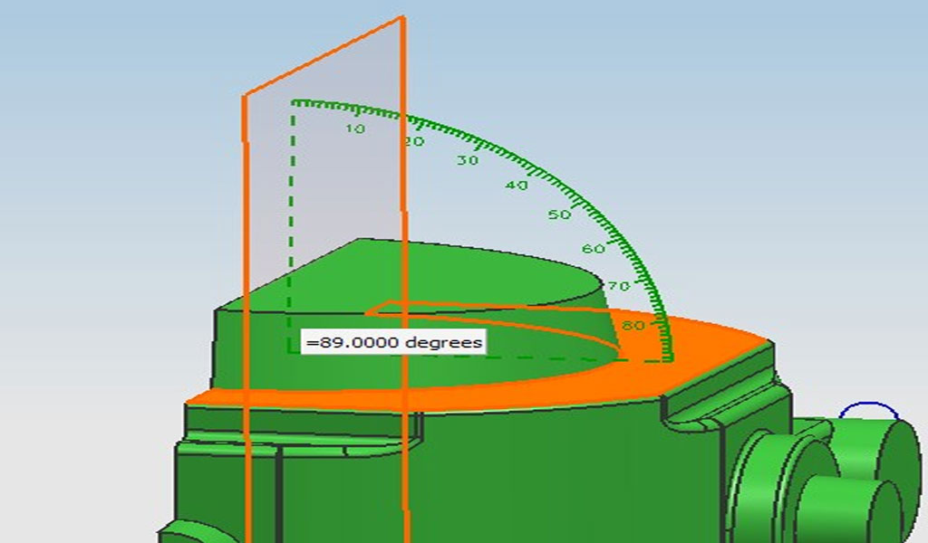
Precision designs typically require smaller draft angles, especially for products with greater depth or height, where the deviation X must be controlled within a specific range. For example, for a 100mm high product requiring precision, the deviation should ideally be kept within 0.15 mm, corresponding to tanθ = 0.005, θ ≈ 0.25°. Achieving such angles can be challenging in molding but is increasingly feasible with advances in precision molding machines and molds. If demands cannot be met, sliders should be considered as a solution.
Parting Surface and Demolding Direction
Figure 2 illustrates how the location of the parting surface affects the draft angle direction. Figure 2(a) shows the original design without draft angles.
Depending on the parting surface position, Figure 2(b) depicts scenarios where one part (A) can be demolded while another (B) cannot, necessitating opposite draft angles that can lead to uneven wall thickness. This aspect should be considered when designing wall thicknesses or ribs.
Principles of Determining Draft Angles
- When materials exhibit high shrinkage resistance, larger draft angles should be used.
- Larger shrinkage and higher pouring temperatures also necessitate larger draft angles.
- For parts with larger demolding dimensions, larger draft angles are required.
- The smoother the mold cavity surface (i.e., lower surface roughness), the smaller the draft angle required.
In fluid pressure forming, part walls are generally thinner, necessitating increased draft angles to compensate for increased wall thickness. When dimensional accuracy requirements for parts are not high or specifications are not explicitly defined on drawings, external and protruding draft angles are typically set at 0.30°, while internal cavities, holes, and recessed areas are set at 1°. For parts with higher overall dimensional accuracy requirements or specific dimensional tolerance demands on drawings, draft angles should be controlled within the tolerance range.
Practical Application Of Draft Angle
In actual production, the draft angles machined into molds are often smaller than those indicated on drawings. After trial molding, draft angles may be adjusted accordingly at locations where parts exhibit scratching or flash, and corresponding adjustments made to the mold.
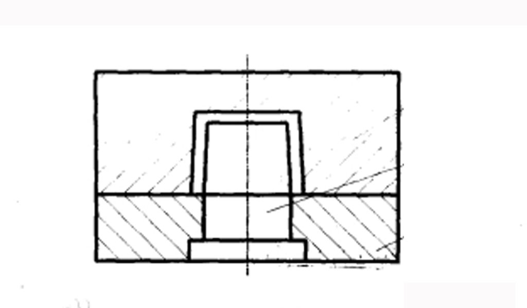
During mold design, maximum draft angles are applied to cores or ejector pins within a certain height range, while minimum draft angles are applied to mold cavities, as shown in Figures 1-11. Applying maximum draft angles to cores and minimum draft angles to movable mold cavities allows for adjustments based on actual part conditions post-trial molding.
In fluid pressure molding machines, the ejection mechanism in the movable mold section ensures that parts remain in the movable mold after opening for effective ejection. When designing molds and unsure which mold half the part will remain on post-opening, draft angles are adjusted appropriately within the part’s dimensional tolerance range to ensure parts remain on the intended mold half. Figure 1-12 illustrates this scenario where concentricity requirements (d1, d2, d3, d4) necessitate parting planes at points A~A and d1 and d2 sharing the same core, making it difficult to determine which mold half the part will adhere to post-opening.
Designing the draft angle to be as small as possible on the movable mold and larger on the stationary mold (within the part’s dimensional tolerance) ensures parts remain on the movable mold after opening.
In the design of plastic products, inclined angles (draft angles) are typically included on both the inner and outer edges to facilitate easy removal from the mold. Products with vertical outer walls aligned with the opening direction of the mold require significant opening force post-molding. Conversely, if the design includes draft angles and all mold components contacting the product are highly polished during processing, demolding becomes effortless. Therefore, considering draft angles during product design is crucial, as injected parts often adhere to the ejector side; thus, equal draft angles are necessary for both the ejector and core molds to ensure uniform wall thickness and prevent parts from adhering to the hotter core mold. However, in specific cases where parts are required to adhere to the core mold after opening, draft angles on the corresponding core mold sections can be minimized or deliberate undercuts can be added to facilitate this process.
How to Calculate Draft Angle For Injection Moulding
Calculating the draft angle for injection molding involves considering several factors related to the material, part geometry, mold design, and surface finish requirements.
The goal is to ensure that the molded part can be easily ejected from the mold without causing damage to either the part or the mold itself. Here’s a detailed guide on how to calculate draft angle for injection molding:
Factors Influencing Draft Angle Calculation
- Material Characteristics:Different plastics have varying shrinkage rates as they cool and solidify. Materials with higher shrinkage rates typically require larger draft angles to facilitate easy part release.Consider the type of plastic being used, its viscosity, and thermal properties which affect how it flows and solidifies within the mold.
- Part Geometry:Complex part geometries, such as deep cavities, undercuts, or intricate features, may require larger draft angles to ensure smooth ejection from the mold.Sharp corners or deep recesses can cause the part to stick if draft angles are insufficient.
- Mold Design:The surface finish of the mold cavity plays a crucial role. A polished or smooth surface reduces friction during ejection, allowing for smaller draft angles.Textured or rough surfaces require larger draft angles to prevent sticking.
- Ejection Mechanism:The method used to eject the part from the mold affects the draft angle calculation. For example, automated ejection systems may tolerate smaller draft angles compared to manual ejection methods.
General Guidelines: Minimum Draft Angle For Injection Moulding
- Minimum Draft Angle: It’s generally recommended to have a minimum draft angle of at least 1 degree on all vertical faces. This ensures easier ejection and reduces the risk of damage to the mold and part.
- Depth of Cavity: Increase the draft angle with the depth of the cavity. A common guideline is to add 1 degree of draft per inch of cavity depth. For example, a cavity that is 2 inches deep would typically require a draft angle of around 2 degrees.
- Part Complexity: More complex parts may require larger draft angles. For parts with deep or intricate features, draft angles can range from 1 to 5 degrees or more, depending on the specific geometry and material used.
Step-by-Step Calculation Process
Identify the Critical Faces:
Determine which faces of the part are vertical or near-vertical in the mold cavity.
Measure the Cavity Depth:
Measure the depth of the cavity where the draft angle needs to be applied. This is crucial as it determines the degree of taper required.
Consider Material Shrinkage:
Consult material datasheets or testing data to understand the shrinkage characteristics of the plastic being used. Higher shrinkage rates necessitate larger draft angles to accommodate dimensional changes during cooling.
Surface Finish Requirements:
Assess the required surface finish of the molded part. Smoother finishes allow for smaller draft angles, while textured finishes require larger angles to ensure easy release.
Calculate the Draft Angle:
Use the formula: Draft Angle=(Depth of Cavity×Draft per Inch)/Depth of Cavity in Inches
Determine the appropriate draft per inch based on material and mold surface conditions.
Apply the calculated draft angle uniformly to all vertical or near-vertical faces of the part in the mold design.
Example Calculation
Let’s assume you have a mold cavity with a depth of 3 inches and you’re using a plastic material with moderate shrinkage rates. Based on your mold surface finish and part geometry analysis, you determine that a draft angle of 1 degree per inch of depth is suitable.
Draft Angle=(3 inches×1∘/inch)/3 inches=1∘
Therefore, a draft angle of 1 degree would be applied to all vertical or near-vertical faces of the part in this specific mold cavity.
Calculating the draft angle for injection molding involves a careful consideration of material properties, part geometry, mold design, and surface finish requirements. By applying appropriate draft angles, manufacturers can ensure smooth part ejection, minimize production costs, and optimize the overall quality and efficiency of the injection molding process. Always refer to specific material and mold design guidelines to tailor the draft angle calculation to your particular manufacturing needs.
How to Calculate Draft Angle For Vacuum Forming
Calculating the draft angle for vacuum forming and vacuum casting involves considering several factors to ensure successful part release from the mold. Here’s a step-by-step guide on how to determine the appropriate draft angle for vacuum-formed parts:
1. Understand the Basics of Draft Angle in Vacuum Forming
Draft angle is the slight taper applied to vertical walls of a mold to allow for easy removal of the formed part from the mold cavity. In vacuum forming, this is crucial because the formed sheet material (often thermoplastic) needs to release smoothly from the mold after cooling.
2. Consider Material Characteristics
Different materials have varying shrinkage rates and surface friction properties. These factors influence the required draft angle:
- Shrinkage Rate: Materials with higher shrinkage rates require larger draft angles to compensate for dimensional changes during cooling.
- Surface Friction: Higher friction between the mold and the material may require larger draft angles to ensure easy release.
3. Determine Part Geometry
The shape and complexity of the part being formed affect the draft angle:
- Straight Sides: Parts with straight sides generally require less draft angle compared to parts with complex contours.
- Undercuts and Details: Areas with undercuts or deep features may require larger draft angles or additional considerations like side actions or split molds.
4. Calculate the Draft Angle
To calculate the draft angle for vacuum forming, a general guideline is to use the tangent of the angle, which can be derived from the following formula:
tan(θ)=X/H
where:
- θ is the draft angle in degrees.
- X is the draft allowance (typically in mm or inches), representing the taper distance over the height of the formed part.
- H is the height of the formed part.
Example Calculation:
Let’s say you have a vacuum-formed part with a height H of 100 mm and you want to apply a draft allowance X of 2 mm.
- tan(θ)=2 mm/100 m
- tan(θ)=0.02
- θ=tan−1(0.02)
- θ≈1.15∘
So, in this example, the draft angle θ would be approximately 1.15 degrees.
5. Practical Considerations
- Round Up: Draft angles are often rounded up to the nearest whole number for practical purposes and ease of manufacturing.
- Testing and Iteration: It’s important to test the draft angle on prototype molds to ensure parts release smoothly without sticking or distortion.
- Consultation: For complex designs or unfamiliar materials, consulting with mold makers or experienced vacuum forming technicians can provide valuable insights.
6. Adjustments Based on Experience
Draft angles in vacuum forming can vary based on specific materials, mold surface finishes, and part geometries. Experience with similar projects and materials can guide adjustments to ensure optimal part release and quality.
By carefully calculating and implementing draft angles in vacuum forming, you can improve manufacturing efficiency, reduce part defects, and ensure consistent quality in formed plastic parts.
How to Calculate Draft Angle For Casting
Calculating draft angles for die casting and investment casting involves considerations similar to those for injection molding, but with specific adjustments based on the metal casting process and material properties. Draft angles are crucial in these processes to facilitate the removal of the solidified casting from the mold or pattern without damaging either the casting or the mold. Here’s a detailed guide on how to calculate draft angles for both die casting and investment casting:
Calculate Draft Angle for Die Castings
Die casting involves injecting molten metal into a steel mold cavity under high pressure. The mold, known as a die, is typically made from hardened steel and consists of two halves: the cover die (or ejector die) and the ejector die (or core die). Proper draft angles are essential for efficient part ejection and maintaining the integrity of the mold. Here’s how to calculate draft angles for die casting:
Identify Critical Faces:
Determine which faces of the part are vertical or near-vertical in the die cavity.
Consider Part Complexity:
Evaluate the complexity of the part geometry, including undercuts, deep cavities, and intricate features. More complex parts may require larger draft angles.
Material Characteristics:
Different metals have varying solidification shrinkage rates. Consult material datasheets or casting simulation software to determine the shrinkage characteristics of the specific metal alloy being used.
Surface Finish Requirements:
Determine the required surface finish of the die-cast part. Smoother finishes generally allow for smaller draft angles, while textured or rough finishes may require larger angles to ensure easy release.
Calculate the Draft Angle:
A common guideline for die casting is to apply a draft angle of 1 to 3 degrees. However, this can vary based on the factors mentioned above.
Draft Angle=(Depth of Cavity×Draft per Inch)/Depth of Cavity in Inches
Depth of Cavity: Measure the depth of the die cavity where the draft angle needs to be applied.
Draft per Inch: Determine the appropriate draft per inch based on material shrinkage and surface finish requirements.
Example Calculation for Die Casting:
Assume you have a die cavity with a depth of 2 inches for casting a zinc alloy part with moderate shrinkage rates. Based on your surface finish requirements and part geometry analysis, you determine that a draft angle of 2 degrees is appropriate.
Draft Angle=(2 inches×2∘/inch)/2 inches=2∘
Therefore, a draft angle of 2 degrees would be applied uniformly to all vertical or near-vertical faces of the part in the die casting process.
Calculate Draft Angle for Investment Castings
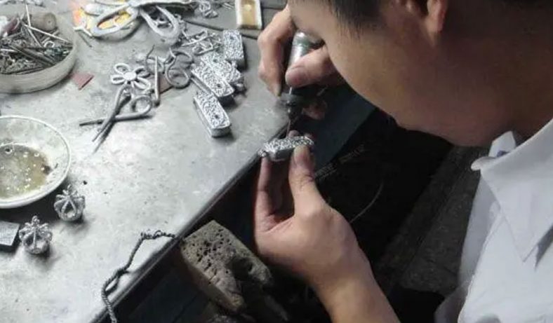
Investment casting, also known as lost-wax casting, involves creating a wax pattern that is coated with a ceramic material. Once the ceramic mold is formed, the wax is melted and drained, leaving a cavity that is then filled with molten metal. Draft angles are critical in investment casting to ensure the easy removal of the wax pattern and the solidified casting from the ceramic mold. Here’s how to calculate draft angles for investment casting:
Identify Critical Faces:
Determine which surfaces of the wax pattern or ceramic mold require draft angles for easy removal.
Evaluate Pattern and Mold Complexity:
Consider the complexity of the wax pattern and ceramic mold design. Intricate details or deep undercuts may necessitate larger draft angles.
Material Characteristics:
Different wax materials and ceramic shell materials have specific shrinkage rates and thermal expansion properties. These factors influence the required draft angles for successful casting.
Surface Finish Requirements:
Determine the surface finish requirements for the final casting. Smooth surfaces may allow for smaller draft angles, while textured or rough surfaces may require larger angles.
Calculate the Draft Angle:
Draft angles for investment casting typically range from 1 to 5 degrees, depending on the factors mentioned above.
Draft Angle=(Depth of Cavity×Draft per Inch)/Depth of Cavity in Inches
Depth of Cavity: Measure the depth of the cavity where the draft angle needs to be applied, either in the wax pattern or the ceramic mold.
Draft per Inch: Determine the appropriate draft per inch based on material characteristics and surface finish requirements.
Example Calculation for Investment Casting:
Assume you have a ceramic mold cavity with a depth of 3 inches for casting a stainless steel part. Based on your surface finish requirements and mold complexity analysis, you determine that a draft angle of 3 degrees is suitable.
Draft Angle=(3 inches×3∘/inch)/3 inches=3∘
Therefore, a draft angle of 3 degrees would be applied uniformly to all critical surfaces of the wax pattern or ceramic mold in the investment casting process.
Calculating draft angles for die casting and investment casting involves a thoughtful analysis of material properties, part geometry, mold or pattern complexity, and surface finish requirements. By applying appropriate draft angles, manufacturers can ensure smooth part ejection, minimize production costs, and optimize the overall quality and efficiency of the casting process. Always refer to specific material and casting process guidelines to tailor the draft angle calculation to your particular manufacturing needs.
How to Calculate Draft Angle For Forging
Calculating draft angles for forging is essential to ensure the successful ejection of the forged part from the die or mold. Unlike casting and injection molding, metal forging involves shaping metal through compressive forces rather than pouring molten material into a mold. The draft angle in forging is crucial for facilitating the removal of the forged part from the die without causing damage to either the part or the die. Here’s a comprehensive guide on how to calculate draft angles for forging:
Factors Influencing Draft Angle Calculation
Material Characteristics:
Different metals have varying degrees of ductility and flow characteristics when subjected to forging. Understanding these properties helps determine the appropriate draft angle.
High-strength materials may require larger draft angles to facilitate easier ejection from the die.
Part Geometry:
The complexity of the part design influences the required draft angle. Deep cavities, undercuts, and intricate features may necessitate larger draft angles to ensure smooth ejection.
Simple parts may require smaller draft angles.
Die Design:
Consider the design of the forging die or tooling. The surface finish and texture of the die impact the frictional forces during ejection.
A polished die surface allows for smaller draft angles, while textured or rough surfaces require larger angles to prevent sticking.
Ejection Mechanism:
The method used to eject the forged part from the die affects the draft angle calculation. Hydraulic or mechanical ejection systems may allow for smaller draft angles compared to manual methods.
General Guidelines for Draft Angle Calculation
- Minimum Draft Angle: It’s generally recommended to have a minimum draft angle of at least 2 degrees on all vertical or near-vertical faces of the forging die.
- Increase with Depth: Increase the draft angle with the depth of the cavity in the forging die. A common guideline is to add 1 degree of draft per inch of cavity depth.
- Part Complexity: More complex parts typically require larger draft angles. For parts with deep cavities or intricate features, draft angles can range from 2 to 7 degrees or more, depending on the specific geometry and material used.
Step-by-Step Calculation Process
Identify the Critical Faces:
Determine which surfaces of the forged part will be vertical or near-vertical in the forging die.
Measure the Die Cavity Depth:
Measure the depth of the cavity in the forging die where the draft angle needs to be applied. This measurement is crucial for determining the degree of taper required.
Consider Material Flow and Die Design:
Evaluate how the material flows within the die during forging. The draft angle must accommodate the movement of the metal to ensure complete filling of the die cavity without causing defects.
Factor in the die design, including any necessary allowances for metal flow and part ejection.
Calculate the Draft Angle:
Draft Angle=(Depth of Cavity×Draft per Inch)/Depth of Cavity in Inches
Depth of Cavity: Measure the depth of the die cavity where the draft angle needs to be applied.
Draft per Inch: Determine the appropriate draft per inch based on material flow characteristics and die surface conditions.
Example Calculation for Forging
Let’s assume you have a forging die cavity with a depth of 4 inches for shaping a steel alloy part. Based on your analysis of part complexity and die surface finish, you determine that a draft angle of 3 degrees is appropriate.
Draft Angle=(4 inches×3∘/inch)/4 inches=3∘
Therefore, a draft angle of 3 degrees would be uniformly applied to all vertical or near-vertical faces of the forging die cavity.
Calculating draft angles for forging involves considering material characteristics, part geometry, die design, and ejection requirements. By applying appropriate draft angles, manufacturers can ensure smooth part ejection, minimize die wear, and optimize the overall quality and efficiency of the forging process. Always refer to specific material and die design guidelines to tailor the draft angle calculation to your particular manufacturing needs.
Be-Cu Prototype – The Best Prototoype Parts to Mass Production Company in China
Injection molding,vacuum forming,casting and forging can crank out identical parts quickly and efficiently. This high-volume and repeatable process saves time and money for complex parts, but choosing the right manufacturer is key. Not all China-based mass parts production service providers offer the same quality, so research is crucial.
Here at Be-Cu.com, we work with many companies looking to require affordable and fast mass prototype production services for low-volume production of up to 100,000 parts. Moreover, we make sure their parts are identical to their final versions using production-grade materials. These capabilities put us among the best prototype manufacturing partners for designers and engineers in various industries, such as automotive, aerospace, telecommunications, and medical.


You can engage us for our manufacturing service with a low upfront investment. This comes with the flexibility that this manufacturing solution offers, allowing us to make prototypes from production materials, deliver low-volume parts, produce models for market testing, and so on. Plus, our team can review your project and provide design tips that can further reduce the lead time and cost.
Do you need a custom mold for parts mmass production? Contact us for a free project review and a quote.