
Geometric Dimensioning and Tolerancing (GD&T) is a symbolic language used in engineering and manufacturing to communicate design specifications and tolerances effectively. It offers a standardized method for defining the permissible variations in form, size, orientation, and location of features on a part or assembly.
Among the various GD&T controls, runout tolerance holds particular importance. Runout defines the allowable variation in a feature’s circularity, coaxiality, or total indicated runout (TIR). It specifies the permissible amount of wobble or variation of a surface or feature in relation to a datum axis or centerline.
What is Runout Tolerance?
Runout Tolerance, within the framework of Geometric Dimensioning and Tolerancing (GD&T), refers to a crucial specification that defines the allowable deviation of a surface or feature in relation to a specified datum or axis.
It’s used to control the variation in circular elements like surfaces, edges, or features to ensure proper rotation, concentricity, and overall functionality of mechanical parts.
Runout Tolerance is crucial in ensuring the smooth operation of rotating parts, such as shafts, gears, and bearings. It helps maintain the proper alignment of components, minimizing vibration, reducing wear and tear, and ensuring optimal functionality in assemblies.
There are primarily three types of Runout Tolerances within GD&T:
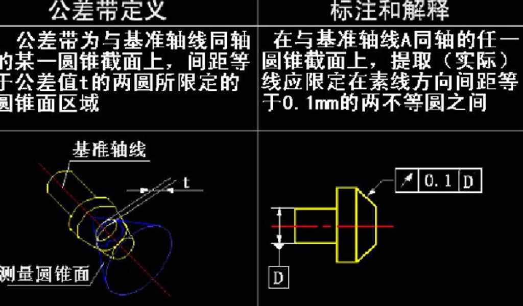
- Total Runout: This type of tolerance controls the cumulative variation of a surface in all directions around a datum axis. It ensures that the entire surface of a part does not deviate excessively from a specified axis, thus guaranteeing proper concentricity and alignment.
- Circular Runout: Circular Runout tolerance focuses specifically on controlling the circularity deviation of a surface relative to a datum axis. It ensures that the circular features of a part, such as the outside diameter of a cylindrical object, remain within specified tolerances during rotation.
- Profile Runout: Profile Runout tolerance governs the orientation and form deviation of a feature or surface relative to a specified datum. It ensures that the form of the feature does not deviate excessively from the specified tolerance zone, guaranteeing proper functionality and fit.
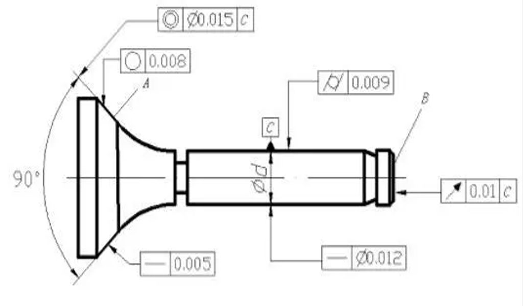
Each type of Runout Tolerance is represented by specific GD&T symbols on engineering drawings, indicating the permissible limits within which the part’s surfaces or features can deviate from their ideal shape or orientation.
In essence, Runout Tolerance is critical in ensuring that rotating parts and components maintain proper alignment, concentricity, and functionality within acceptable limits, as specified by engineering design requirements. It helps in manufacturing processes by providing clear guidelines to maintain precision, reduce errors, and ensure the proper functioning of mechanical assemblies.
What is Circular Runout Tolerance?
Circular Runout Tolerance is a fundamental aspect of Geometric Dimensioning and Tolerancing (GD&T tolerance) used to control the circularity deviation of a surface or feature relative to a specified datum axis.
It ensures that circular elements, such as the periphery of a cylindrical part, remain within specified tolerances during rotation.Circular Runout is particularly important for parts that involve rotational movement, such as shafts, cylinders, and rotating components in machinery.
It defines the allowable variation in the circular form of a feature, ensuring that it rotates without wobbling or excessive deviation from its intended circular path.Key aspects of Circular Runout Tolerance:
- Datum Axis: It refers to a specified axis or line from which the circularity of the feature is measured. The feature’s deviation from this axis is evaluated to ensure it remains within acceptable limits.
- Tolerance Zone: Circular Runout specifies a tolerance zone around the datum axis within which the circular feature must lie. This tolerance zone defines the allowable deviation in the circularity of the feature.
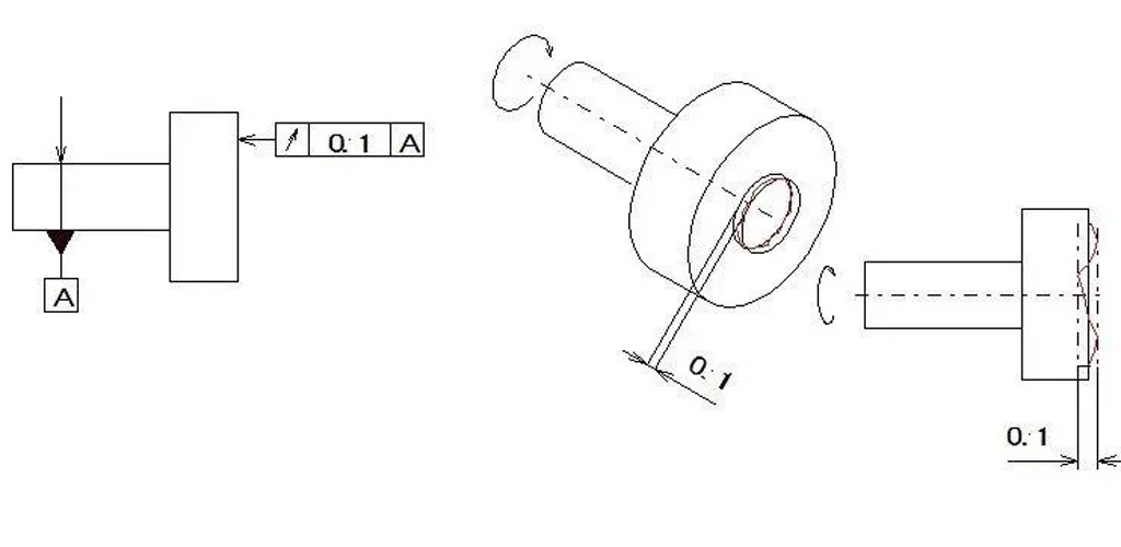
- Measurement and Evaluation: Circular Runout is measured using specialized tools such as dial indicators, micrometers, or coordinate measuring machines (CMMs). The feature is rotated, and deviations from the datum axis are measured and compared against the specified tolerances.
- Representation in GD&T: Circular Runout Tolerance is symbolized in engineering drawings using specific GD&T symbols. The symbol indicates the tolerance value and any additional information necessary for proper interpretation and manufacturing.
Circular Runout Tolerance ensures that circular features are manufactured within acceptable limits to maintain proper alignment, reduce vibration, ensure smooth rotation, and guarantee functionality within assemblies. It helps in controlling variations in circular elements, minimizing manufacturing defects and ensuring parts’ proper fit and function within mechanical systems.
What is Total Runout Tolerance?
Total Runout Tolerance, a vital aspect of Geometric Dimensioning and Tolerancing (GD&T), controls the composite variation of a surface or feature in all directions around a specified datum axis. It ensures that the entire surface of a part does not deviate excessively from a specified axis when measured in all orientations or GD&T positions.Key points about Total Runout Tolerance:
- Datum Axis: Similar to other GD&T tolerances, Total Runout also relies on a datum reference, which could be a line, plane, or axis, from which the deviations are measured. This datum axis serves as a reference for the entire feature or surface.
- Tolerance Zone: Total Runout defines a tolerance zone within which the entire surface or feature must lie when rotated or positioned in various orientations. The tolerance zone encompasses all possible variations of the feature relative to the datum axis.
- Measurement and Evaluation: Measurement of Total Runout often involves specialized equipment like coordinate measuring machines (CMMs), optical comparators, or precision gauges. The feature is checked for deviations from the datum axis in multiple positions to ensure compliance with specified tolerances.
- GD&T Representation: Total Runout Tolerance is symbolized in engineering drawings using specific GD&T symbols. The symbol denotes the tolerance value, the datum reference, and any other relevant information required for accurate interpretation and manufacturing.
Total Runout Tolerance is crucial in ensuring the concentricity, alignment, and proper functioning of rotating parts or features in assemblies. It’s particularly essential for components such as gears, shafts, bearings, and any part requiring precise rotational alignment. By controlling the composite variation of surfaces or features, Total Runout helps minimize errors, ensures proper assembly, reduces vibration, and maintains the integrity and functionality of mechanical systems.
What is Profile Runout Tolerance?
Profile Runout Tolerance is a key aspect of Geometric Dimensioning and Tolerancing (GD&T) that controls the orientation and form deviation of a feature or surface relative to a specified datum. It ensures that the profile of the feature maintains its intended shape and orientation within specified tolerances.Key points about Profile Runout Tolerance:
- Datum Reference: Similar to other GD&T tolerances, Profile Runout relies on a specified datum reference, such as a plane, line, or axis, from which the deviations in orientation and form are measured. This datum serves as a reference for evaluating the feature’s deviations.
- Tolerance Zone: Profile Runout defines a tolerance zone within which the entire profile or form of the feature must lie when positioned or oriented in various ways relative to the datum. The tolerance zone specifies acceptable deviations from the intended form and orientation.
- Application: It is crucial for ensuring that specific features or surfaces maintain their intended form, orientation, and relationship to the datum. Profile Runout is often used in parts where the geometric shape, such as contours, surfaces, or features with specific orientations, is critical for functionality or assembly.
- Measurement and Evaluation: Measuring Profile Runout involves assessing the deviations of the feature’s form and orientation relative to the datum. Techniques such as CMMs, height gauges, or specialized fixtures are used to verify compliance with specified tolerances.
- GD&T Representation: Profile Runout Tolerance is symbolized in engineering drawings using specific GD&T symbols. The symbol indicates the tolerance value, the datum reference, and any other relevant information essential for accurate interpretation and manufacturing.
Profile Runout Tolerance is significant for ensuring the proper orientation, form, and relationship of specific features within a part or assembly. It helps maintain functionality, proper assembly, and compatibility between mating parts by controlling deviations in orientation and form. This tolerance ensures that critical geometric features align correctly according to design specifications, enhancing the overall quality and functionality of the manufactured parts.
Distinguishing Circular Runout Tolerance from Total Runout Tolerance
Circular Runout Tolerance and Total Runout Tolerance are both crucial aspects of Geometric Dimensioning and Tolerancing (GD&T) used in engineering drawings to control the variation of features or surfaces relative to specified datums. While they share similarities, they have distinct characteristics and applications:
Circular Runout Tolerance:
- Focus: Circular Runout specifically controls the circularity deviation of a feature relative to a specified datum axis. It ensures that circular elements, such as the periphery of a cylindrical part or a circular surface, remain within specified tolerances during rotation.
- Application: It is primarily employed in situations where the roundness or circular form of a feature is critical, especially for rotating parts like shafts, bearings, and cylindrical components. The goal is to ensure smooth rotation without excessive wobbling or deviation from the intended circular path.
- Measurement: Circular Runout is measured by inspecting the deviation of the feature from the datum axis in various positions as it rotates. Specialized measuring tools like dial indicators, micrometers, or coordinate measuring machines (CMMs) are used for precise evaluation.
Total Runout Tolerance:
- Scope: Total Runout controls the composite variation of a surface or feature in all directions around a specified datum axis. It ensures that the entire surface or feature does not deviate excessively from the datum axis when measured in multiple orientations.
- Application: It is crucial for maintaining overall concentricity, alignment, and proper functionality of parts or assemblies, especially those involving multiple features and complex geometries. Total Runout ensures that the entire surface or feature is within specified tolerances regardless of its orientation.
- Measurement: Evaluating Total Runout involves checking the variation of the entire surface or feature relative to the datum axis in different positions or orientations. Measurement tools such as CMMs, optical comparators, or precision gauges are used to verify compliance.
Distinction:
- Focus: Circular Runout specifically addresses circularity deviation, while Total Runout considers the overall variation of a feature in all directions.
- Application: Circular Runout is more specific and useful for rotational parts, whereas Total Runout is broader and applicable to various complex surfaces and features.
- Measurement: Both require careful measurement, but Circular Runout focuses on deviations in circular elements, while Total Runout assesses variations in all orientations.
Circular Runout is more specific to controlling circular deviation, whereas Total Runout addresses the composite variation of a feature in all directions, ensuring overall alignment and functionality. Both are vital for ensuring precise manufacturing and assembly of mechanical components but serve different purposes based on their specific applications and measurement approaches.
Distinguishing Chart Of Total Runout,Circular Runout and Profile Runout
Here’s a chart table that outlines the distinguishing characteristics of Total Runout, Circular Runout, and Profile Runout Tolerances:
| Aspect | Total Runout | Circular Runout | Profile Runout |
|---|---|---|---|
| Focus | Controls composite variation of a feature in all directions around a specified datum axis. | Controls circularity deviation of a feature relative to a specified datum axis. | Controls orientation and form deviation of a feature or surface relative to a specified datum. |
| Application | Ensures overall concentricity, alignment, and functionality of parts or assemblies. | Ensures circular elements’ circularity deviation for rotating parts. | Ensures specific features or surfaces maintain intended form, orientation, and relationship to the datum. |
| Datum Reference | Relies on a specified datum axis for measurement of variations in all orientations. | Focuses on deviations from a specified circular datum axis. | Requires a specified datum for evaluation of form and orientation deviations. |
| Tolerance Zone | Specifies a zone encompassing all possible variations around the datum axis. | Defines a tolerance zone around the circular datum axis for circularity deviations. | Establishes a tolerance zone for acceptable form and orientation deviations relative to the datum. |
| Measurement | Involves checking variations of the entire feature in different orientations relative to the datum axis. | Requires evaluation of circularity deviations of the feature as it rotates. | Involves measuring deviations in form and orientation relative to the datum reference. |
| GD&T Symbol | Represented by specific GD&T symbols denoting overall feature variation. | Symbolized by GD&T symbols specific to circularity control. | Symbolized using GD&T symbols indicating form and orientation deviations. |
| Purpose | Ensures overall alignment, concentricity, and functionality in all orientations. | Ensures proper circularity and alignment in rotating parts. | Ensures specific feature form, orientation, and relationship according to design specifications. |
By following the guidelines above, engineers and machinists can effectively apply and measure runout tolerances to maintain the quality and functionality of rotating components.