
PolyJet is an advanced additive manufacturing technology renowned for its ability to produce high-resolution, multi-material parts with exceptional surface finish and precision. Developed by Objet Geometries (now part of Stratasys), PolyJet leverages inkjet printing principles to jet photopolymer resins onto a build platform, where they are immediately cured by ultraviolet (UV) light. Among its many capabilities, PolyJet excels in creating transparent or translucent parts, making it a preferred choice in industries such as medical device manufacturing, automotive design, consumer goods prototyping, and scientific visualization. Achieving clarity with PolyJet-printed parts, however, requires a nuanced understanding of the technology, material properties, design considerations, printing parameters, and post-processing techniques. This article explores the multifaceted process of achieving clarity with PolyJet, delving into the scientific principles, practical methodologies, and comparative analyses that underpin this capability.
Overview of PolyJet Technology
PolyJet operates by depositing micro-droplets of liquid photopolymer resin through multiple jetting heads onto a build tray. Each droplet, typically 16–30 micrometers (µm) in layer thickness, is cured instantly by UV lamps integrated into the print head assembly. This layer-by-layer process allows for intricate geometries, smooth surfaces, and the simultaneous use of multiple materials within a single print. The technology’s precision stems from its high-resolution jetting system, capable of achieving horizontal resolutions up to 600 dots per inch (dpi) and dimensional accuracies as tight as ±0.1 mm for small parts, with tolerances scaling to ±0.2% for larger components.
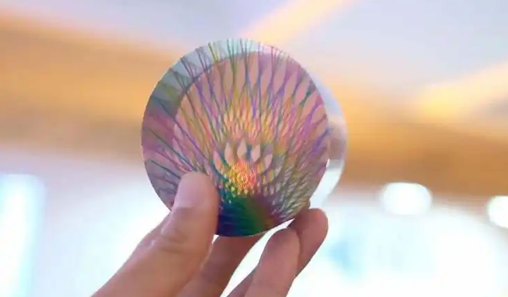
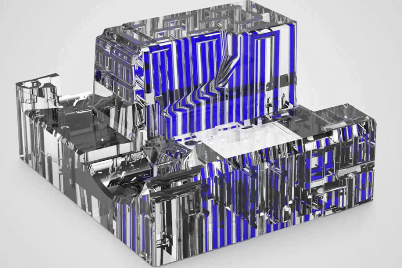
The ability to produce clear parts is facilitated by specific transparent photopolymers, such as Stratasys’ VeroClear or Xometry’s Translucent, Clear Photopolymer. These materials mimic the optical properties of poly(methyl methacrylate) (PMMA), commonly known as acrylic, offering high light transmission and low haze when properly processed. However, as-printed PolyJet parts often exhibit a slightly matte or frosted appearance due to layer lines and surface imperfections inherent to the additive process. Achieving optical clarity—defined as a state where light passes through the material with minimal scattering or distortion—requires both optimized printing and meticulous post-processing.
Material Science of Transparent Photopolymers
The photopolymers used in PolyJet are acrylate-based resins formulated with photoinitiators that trigger polymerization under UV exposure. VeroClear, for instance, is a rigid, transparent resin with a refractive index of approximately 1.47, closely aligning with PMMA (1.49). Its clarity is quantified by metrics such as light transmittance (typically >90% in the visible spectrum after polishing) and haze (a measure of light scattering, ideally <1% for optical applications). The resin’s chemical composition includes monomers, oligomers, and stabilizers, which determine its mechanical and optical properties post-cure.
During printing, the photopolymer’s viscosity (typically 10–20 centipoise at jetting temperature) ensures precise droplet formation, while its curing behavior influences layer adhesion and surface quality. Incomplete curing or residual uncured resin can introduce cloudiness, necessitating thorough UV exposure during printing and, in some cases, additional post-curing. The material’s isotropic nature—unlike the anisotropic properties of fused deposition modeling (FDM) thermoplastics—enhances its suitability for uniform optical performance across all axes.
Design Considerations for Clarity
Achieving clarity begins with the design phase. The geometry of the part significantly impacts light transmission and surface finish. Key design principles include:
- Wall Thickness Optimization: Thin walls (e.g., 0.8–2.0 mm) enhance light penetration but risk warping or cracking during printing or post-processing. Thicker walls (>3 mm) improve structural integrity but may increase internal scattering if not polished uniformly.
- Surface Orientation: Parts oriented with critical surfaces facing upward (Z-axis) benefit from the “glossy” setting in PolyJet software, reducing layer line visibility. However, vertical surfaces may still show striations unless post-processed.
- Avoiding Overhangs and Supports: Support material, typically a water-soluble gel (e.g., SUP706), is used for overhangs and complex geometries. While removable, its interface with the model can leave micro-imperfections, degrading clarity. Designing self-supporting structures minimizes this issue.
- Curvature and Edges: Sharp edges and small radii (<0.5 mm) can concentrate stress and scatter light. Smoothing these features in the CAD model enhances optical quality.
Software tools like GrabCAD Print or Materialise Magics allow designers to simulate light paths through the model, identifying areas prone to distortion. Finite Element Analysis (FEA) can also predict stress concentrations that might affect transparency during post-processing.
Printing Parameters for Optimal Clarity
The PolyJet printing process offers several adjustable parameters that influence clarity:
- Layer Thickness: Options range from 16 µm (high quality) to 55 µm (high speed). Thinner layers reduce visible stepping, improving surface smoothness and light transmission. For example, a 16 µm layer height yields a root mean square (RMS) surface roughness of ~1–2 µm, compared to 5–10 µm at 30 µm.
- Glossy vs. Matte Finish: The “glossy” mode applies additional resin to upper surfaces, minimizing layer lines. Matte mode, while faster, leaves a frosted texture requiring more post-processing for clarity.
- UV Exposure: Overexposure can yellow the resin, while underexposure leaves uncured regions, both compromising clarity. Optimal exposure is machine-specific, typically calibrated by the manufacturer (e.g., Stratasys J-series printers adjust UV intensity dynamically).
- Material Blending: Combining VeroClear with small amounts of tinted resins (e.g., VeroVivid) can adjust translucency without sacrificing optical quality, useful for aesthetic applications.
A typical print setup for clarity might involve a Stratasys J850 Prime printer, VeroClear resin, 16 µm layer height, and glossy mode, with a build time of 4–6 hours for a 100 mm³ part.
Post-Processing Techniques for Enhanced Clarity
As-printed PolyJet parts rarely achieve full optical clarity without post-processing. The following techniques, grounded in materials science and engineering, are essential:
1. Support Removal
Support material is dissolved using a 2% sodium hydroxide (NaOH) solution or a high-pressure water jet (e.g., Stratasys Cleaning Station). Incomplete removal leaves residues that scatter light, so parts are soaked for 1–2 hours, followed by rinsing in deionized water to prevent chemical haze.
2. Wet Sanding
Progressive wet sanding smooths layer lines and micro-imperfections. The process begins with coarse grit (400–600) to remove bulk irregularities, advancing to fine grits (1000–3000) for a polished finish. Sanding reduces surface roughness to <0.5 µm RMS, significantly lowering haze. For a 50 mm² surface, sanding takes approximately 30–60 minutes, depending on geometry.
3. Clear Coating
Applying a UV-curable clear enamel (e.g., Krylon Crystal Clear) fills microscopic voids, enhancing gloss and transmittance. Multiple thin coats (3–5 layers, 10 µm each) are preferred over a single thick coat to avoid drips or unevenness. Each layer cures in 5–10 minutes under ambient UV or a curing lamp, achieving a final haze of <0.5%.
4. Polishing (Optional)
For ultra-clarity, mechanical polishing with a buffing wheel and polishing compound (e.g., aluminum oxide paste) can achieve a mirror finish (<0.1 µm RMS). This step, while time-intensive (1–2 hours), is critical for optical-grade parts like lenses or light guides.
Post-processing can increase light transmittance from ~85% (as-printed) to >95%, rivaling injection-molded PMMA. However, it introduces variables such as operator skill and environmental conditions (e.g., humidity affecting coating adhesion), necessitating controlled workflows.
Scientific Principles Underpinning Clarity
Clarity in PolyJet parts hinges on the physics of light interaction with matter. Light transmission (T) through a material is governed by the Beer-Lambert Law:
T=I/I0=e−αd
where I0I_0I0 is incident light intensity, III is transmitted intensity, α\alphaα is the absorption coefficient, and ddd is material thickness. For VeroClear, α\alphaα is low (~0.01 mm⁻¹), but surface scattering—quantified by the bidirectional reflectance distribution function (BRDF)—increases haze in as-printed parts. Sanding and coating minimize scattering by reducing surface roughness (Ra), aligning the BRDF closer to that of a specular reflector.
Refractive index homogeneity is also critical. Microscopic voids or uncured resin pockets create index mismatches, scattering light via Rayleigh or Mie mechanisms. Post-curing in a UV chamber (e.g., 405 nm, 30 minutes) eliminates these defects, enhancing clarity.
Comparative Analysis of Clarity Across 3D Printing Technologies
To contextualize PolyJet’s clarity capabilities, a comparison with other 3D printing technologies is instructive. The table below evaluates key metrics:
| Technology | Material | Layer Thickness (µm) | As-Printed Clarity | Post-Processed Clarity | Surface Roughness (µm) | Cost ($/cm³) |
|---|---|---|---|---|---|---|
| PolyJet | VeroClear | 16–55 | Translucent (85% T) | Optical (>95% T) | 1–2 (as-printed); <0.5 (polished) | 0.5–1.0 |
| Stereolithography (SLA) | Clear Resin (Formlabs) | 25–100 | Translucent (80% T) | Near-Optical (90% T) | 2–5 (as-printed); <1 (polished) | 0.3–0.7 |
| FDM | Polycarbonate | 100–300 | Opaque (<50% T) | Translucent (70% T) | 10–20 (as-printed); 5–10 (polished) | 0.1–0.3 |
| Selective Laser Sintering (SLS) | PA12 (Nylon) | 80–120 | Opaque (<10% T) | N/A | 5–15 (as-printed) | 0.2–0.5 |
- PolyJet vs. SLA: PolyJet offers finer layer resolution and multi-material flexibility, but SLA’s lower cost and simpler post-processing (e.g., IPA rinse) make it competitive for basic clarity. PolyJet excels in complex, multi-part assemblies requiring transparency.
- PolyJet vs. FDM: FDM’s thermoplastic extrusion limits clarity due to thicker layers and material opacity. Even with transparent filaments, scattering is high, making FDM unsuitable for optical applications.
- PolyJet vs. SLS: SLS produces porous, opaque parts from powder, precluding clarity without infiltration, which PolyJet avoids entirely.
Applications Requiring Clarity
PolyJet’s clarity is leveraged across diverse fields:
- Medical: Transparent anatomical models visualize internal structures (e.g., vascular phantoms with >90% transmittance).
- Optics: Prototypes for lenses or light pipes achieve clarity comparable to glass after polishing.
- Consumer Goods: Packaging mockups or display components benefit from aesthetic transparency.
- Scientific Research: Microfluidic devices printed with biocompatible clear resins (e.g., MED610) enable cellular observation.
Challenges and Limitations
Despite its strengths, achieving clarity with PolyJet faces challenges:
- Cost: At $0.5–1.0/cm³, PolyJet is pricier than FDM or SLS, limiting scalability.
- Durability: Photopolymers are less robust than thermoplastics, with tensile strengths of 50–65 MPa vs. 80–100 MPa for nylon.
- Time: Post-processing adds hours to production, offsetting PolyJet’s rapid print speed (e.g., 20 mm/hr in Z-axis).
- Environmental Sensitivity: Yellowing from UV exposure or humidity can degrade clarity over time, requiring protective coatings.
Future Directions
Advancements in PolyJet clarity are emerging. New resins with lower α\alphaα values, automated post-processing systems (e.g., robotic sanding), and AI-driven print optimization promise to streamline workflows. Hybrid systems combining PolyJet with SLA or CNC finishing could further enhance optical quality, pushing transmittance beyond 98%.
Detailed Comparison Table of Post-Processing Techniques
| Technique | Equipment | Time (min) | Surface Roughness (µm) | Transmittance (%) | Cost ($) | Skill Level |
|---|---|---|---|---|---|---|
| Support Removal | NaOH Bath/Water Jet | 60–120 | 2–5 (pre-sanding) | 85–88 | 10–20 | Low |
| Wet Sanding | Sandpaper (400–3000) | 30–60 | 0.5–1 | 90–93 | 5–15 | Moderate |
| Clear Coating | Spray Enamel, UV Lamp | 20–40 | <0.5 | 93–95 | 10–25 | Moderate |
| Mechanical Polishing | Buffing Wheel, Compound | 60–120 | <0.1 | >95 | 20–50 | High |
This table illustrates the trade-offs between time, cost, and optical performance, guiding users to select techniques based on application needs.
The Detail Of BE-CU 3D Printing Company
BE-CU.COM offers online 3D printing services for rapid prototyping and production in volume. Our clients are across a wide variety of industries and companies, including automotive, construction, aerospace, defense, electronics, machinery, industrial automation, medical, healthcare, consumer production, oil & gas, etc. Accelerate your product development and manufacturing process with our industry-leading metal & plastic 3D printing service and 3D printed parts. We’ll find the best 3D printing solution for your projects, to lower your cost and shorten the lead time based on your needs, while maintaining the quality. From 3D prototyping to end-use parts production, multiple materials are available for custom 3D printing parts. Need an alternative to the traditional solution? Submit your 3D CAD file to get an online quotation quickly. Our 3D printing service ensures accuracy and speed. We can help you choose the most appropriate technology and material to match your applications or request.
-
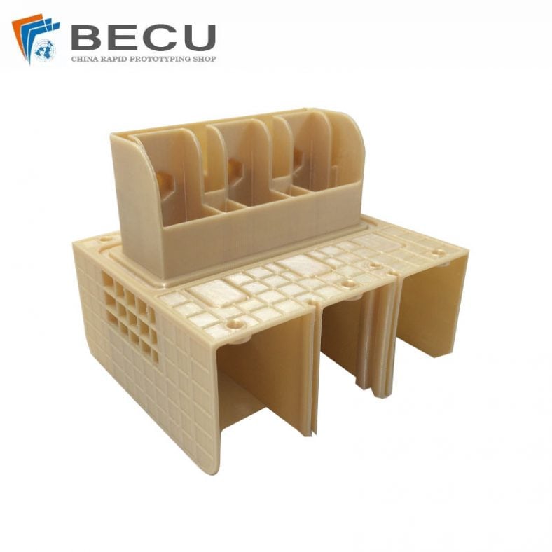
FDM 3D Printing Ultra-High Voltage Strong Electrical Connector
-
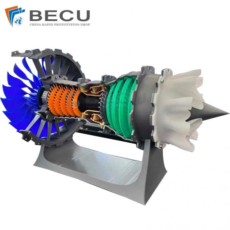
3D Printed Jet Engine Model
-

3D Printed Inconel Exhaust Manifold
-
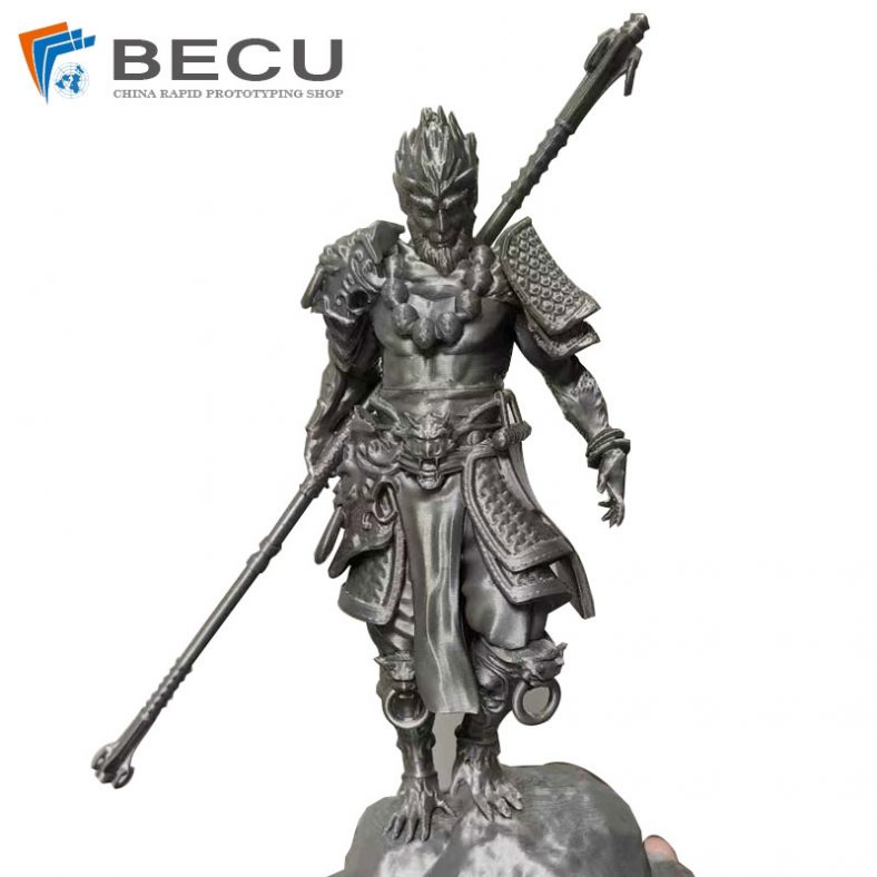
3D Printed Black Myth: Wukong Model
-
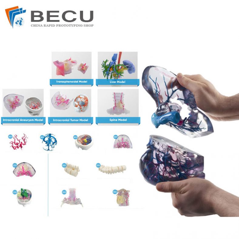
Omni-Directional Surgical Planning Medical Models
-
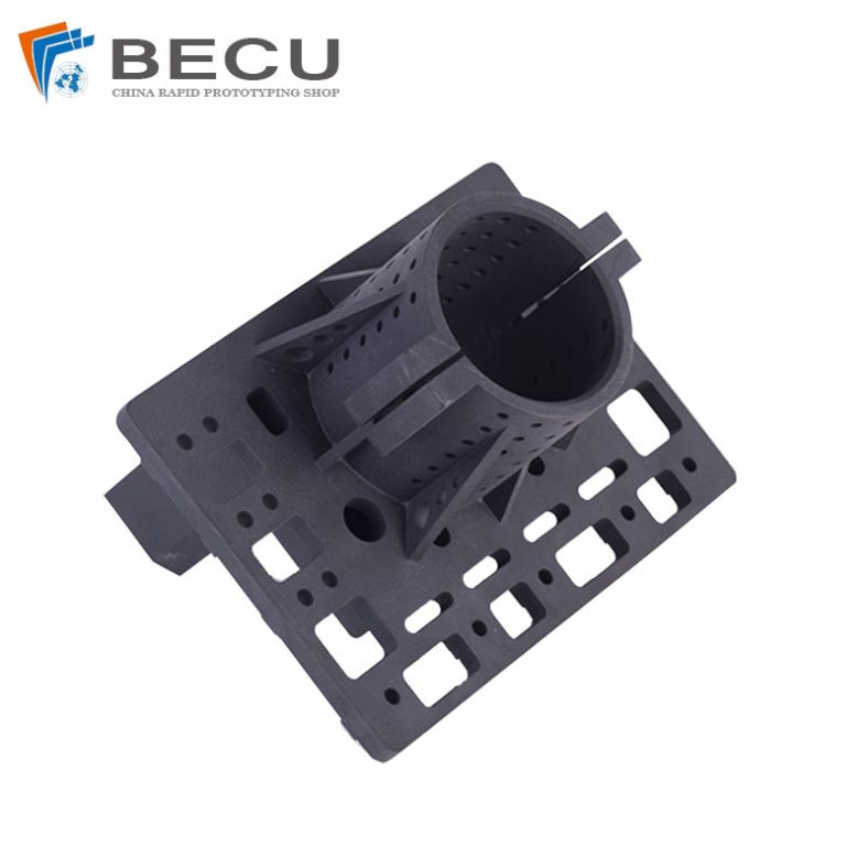
3D Printing Pool Pressure Cleaner Parts and Accessories
-
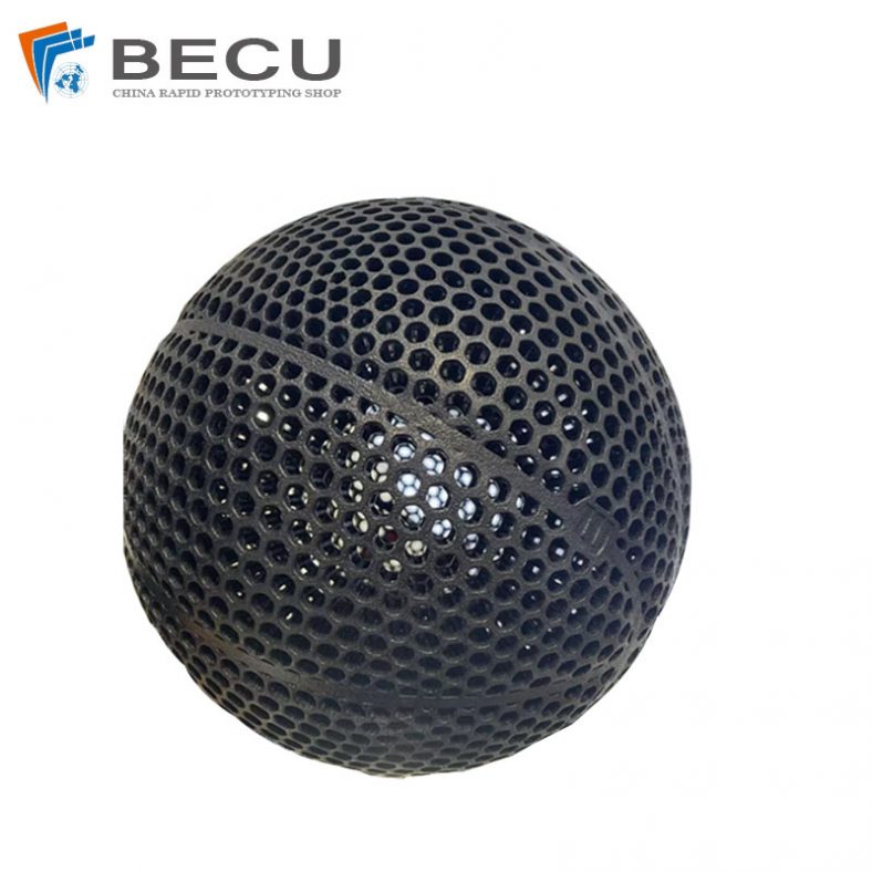
Nylon 3D Printed Size 5 Basketball
-
Black Nylon Medical Threaded Screw By MJF 3D Printing