
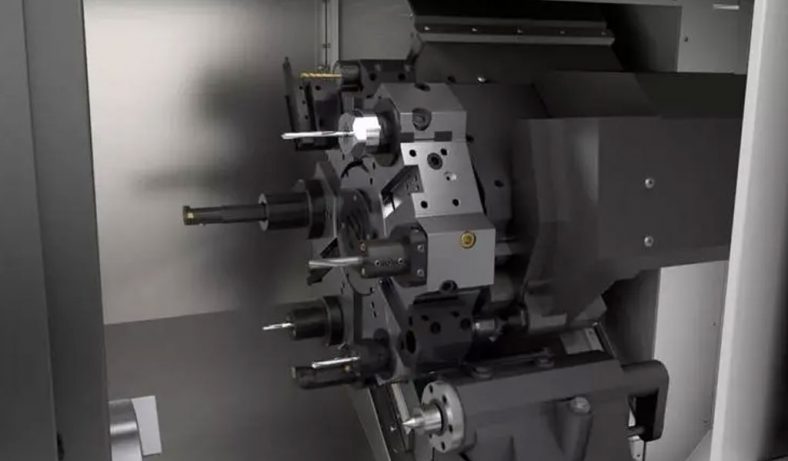
The advent of advanced machining technology has revolutionized the manufacturing industry, enabling precision and efficiency in producing intricate parts. One such innovation is the 9-axis lathe, a powerful machine that combines multiple operations into a single setup. Operating a 9-axis lathe requires a deep understanding of its capabilities, programming, and tooling. In this article, we will delve into the intricacies of running a 9-axis lathe, providing valuable tips and techniques to help you maximize its potential.
Understanding The Basics Of 9-Axis Lathe
A 9-axis lathe, also known as a multi-axis lathe or a mill-turn center, is a computer-controlled machine tool used for precision machining operations.
It combines the functionalities of a lathe and a machining center, allowing for complex part production in a single setup. The term “9-axis” refers to the machine’s ability to perform operations along nine different axes of motion.
9-axis lathes find extensive use in industries such as aerospace, automotive, medical, and precision engineering. They are ideal for producing complex components with tight tolerances, such as turbine blades, aerospace engine parts, medical implants, high-precision automotive components and large parts machining.
1.Axes of Motion
A 9-axis lathe typically incorporates the following axes of motion:
- X-axis: Horizontal movement along the lathe’s bed.
- Y-axis: Vertical movement perpendicular to the lathe’s bed.
- Z-axis: Longitudinal movement along the lathe’s spindle axis.
- C-axis: Rotational movement of the spindle or workpiece.
- B-axis: Tilting movement of the machining head or spindle.
- U, V, and W axes: Additional linear or rotational axes for enhanced flexibility and control.
2.The Benefits Of 9-axis lathe
The key benefits of utilizing a 9-axis lathe include:
- Reduced setup time and increased productivity.
- Enhanced machining capabilities, including multi-axis milling and turning.
- Improved accuracy and precision.
- Increased flexibility for machining complex geometries.
- Streamlined production processes, minimizing part handling and setup errors.
3.Components And Functions Of 9-Axis Lathe
A 9-axis lathe consists of various components that work together to facilitate precise and efficient machining operations. Understanding these components and their functions is essential for operating a 9-axis lathe effectively. Let’s explore the key components and their respective functions:
# Bed
The bed is the base of the lathe and provides a sturdy foundation for other components. It is typically made of cast iron and provides rigidity and stability to the machine.
# Headstock
The headstock houses the main spindle, which rotates the workpiece. It contains components like gears, bearings, and drive mechanisms to provide power and rotational motion.
# Chuck
The chuck is a clamping device mounted on the spindle that holds the workpiece securely during machining. It comes in various types, such as three-jaw chucks, four-jaw chucks, and collets, to accommodate different workpiece shapes and sizes.
# Tailstock
The tailstock is located on the opposite end of the lathe bed from the headstock. It provides additional support to the workpiece and can be adjusted for different lengths. The tailstock often includes a quill that can be extended or retracted to apply pressure against the workpiece.
# Tool Turret
The tool turret is a rotating component that holds multiple cutting tools. It allows for rapid tool changes during machining operations. Each tool is positioned and secured in the turret, ensuring precise alignment and repeatability.
# Tool Holders
Tool holders are clamping devices that secure cutting tools in the tool turret. They provide stability and allow for quick tool changes. Tool holders are designed to accommodate various tool sizes and types, such as turning tools, boring bars, drills, and milling tools.
# Axes and Slides
A 9-axis lathe incorporates multiple axes and slides, each responsible for specific movements during machining.
# Control Panel
The control panel houses the interface through which the operator interacts with the lathe. It includes a control unit, display screen, buttons, and switches for programming, adjusting settings, and monitoring the machining process.
# Coolant System
A 9-axis lathe typically incorporates a coolant system to cool and lubricate the cutting tools, reducing heat and friction. Coolant helps improve tool life, chip evacuation, and surface finish quality.
# Chip Conveyor
A chip conveyor is used to remove chips and debris generated during machining. It collects and transports the chips away from the work area, ensuring a clean and safe working environment.
# Automation and Bar Feeder (Optional)
In some cases, a 9-axis lathe can be equipped with automation features, such as robotic part loading and unloading systems. Additionally, a bar feeder may be integrated to automatically feed long bar stock into the lathe for continuous machining.
Understanding the various components and their functions in a 9-axis lathe enables operators to optimize the machine’s capabilities and carry out precise machining operations. Proper maintenance and periodic inspection of these components are crucial to ensure the machine operates at its best and delivers high-quality china machining parts consistently.
4.Safety Precautions Of 9-Axis Lathe
Safety is of utmost importance when operating any machinery, including a 9-axis lathe. Adhering to proper safety precautions ensures the well-being of operators and reduces the risk of accidents. Here are some essential safety precautions to consider when working with a 9-axis lathe:
- Read and Understand the Manual: Thoroughly read the lathe’s operation manual provided by the manufacturer. Familiarize yourself with the specific safety instructions, machine capabilities, and limitations. Follow the manufacturer’s guidelines for safe operation.
- Wear Personal Protective Equipment (PPE): Always wear appropriate personal protective equipment, including safety glasses or goggles, protective gloves, and safety shoes. Depending on the specific tasks and environment, additional protective gear like a face shield, ear protection, or a respirator may be necessary.
- Ensure Proper Training: Only trained and authorized personnel should operate a 9-axis lathe. Ensure operators receive comprehensive training on lathe operation, safety procedures, and emergency protocols. Regularly update their training as new techniques or features are introduced.
- Maintain a Clean and Organized Workspace: Keep the work area clean, free from clutter, and well-organized. Remove any debris, tools, or materials that are not required for the current machining operation. Properly dispose of waste material and chips to prevent slips, trips, and falls.
- Verify Machine Condition: Before starting the lathe, visually inspect the machine for any signs of damage, loose components, or abnormalities. Ensure all guards and safety devices are in place and functioning correctly. Report any issues to the appropriate personnel and refrain from operating the machine until repairs are made.
- Lockout/Tagout Procedures: Follow proper lockout/tagout procedures when performing maintenance, repairs, or adjustments on the lathe. Disconnect power sources, lockout energy controls, and clearly tag the machine to prevent accidental startup.
- Handle Tools Safely: Use the appropriate tools and tool holders designed for the lathe. Ensure cutting tools are sharp, properly secured, and in good condition. Never reach into the lathe while it is in operation. Wait for the machine to come to a complete stop before making any adjustments or tool changes.
- Monitor Workpiece Setup: Securely clamp the workpiece using the appropriate chuck or collet. Ensure the workpiece is properly aligned, centered, and balanced. Avoid excessive overhangs that may cause vibrations or instability during machining.
- Set Proper Speeds and Feeds: Select appropriate cutting speeds, feeds, and depths of cut based on the workpiece material, tooling, and machining operation. Consult cutting data charts or consult with machining experts to determine the optimal parameters.
- Use Coolant and Lubrication: When required, use coolant or lubrication to reduce heat, lubricate the cutting tools, and evacuate chips effectively. Follow proper procedures for coolant and lubricant handling and ensure that any necessary safety measures, such as splash guards, are in place.
- Emergency Preparedness: Familiarize yourself with the location and proper use of emergency stop buttons, fire extinguishers, first aid kits, and emergency exits. Have clear communication protocols in place for reporting emergencies and ensure operators know how to respond to different situations.
Remember, these safety precautions serve as general guidelines. Always consult the manufacturer’s safety recommendations, industry standards, and local regulations specific to your machine and work environment. Prioritize safety at all times to create a secure and productive working environment when operating a 9-axis lathe.
Programming and Setup Of 9-Axis Lathe – How To Run A 9 Axis Lathe
Programming and setup are crucial steps when operating a 9-axis lathe. Proper programming ensures accurate tool paths and machining operations, while a well-executed setup guarantees the workpiece is securely positioned and aligned. Here is a guide to programming and setup for a 9-axis lathe:
1.CAD/CAM Integration
CAD/CAM integration plays a crucial role in maximizing the capabilities of a 9-axis lathe. It enables efficient programming, accurate tool path generation, and seamless communication between the CAD software for design and the CAM software for generating machine instructions (G-code). Here’s a guide to CAD/CAM integration for a 9-axis lathe:
- CAD Design: Start by creating a detailed 3D model of the part you want to machine using CAD software. CAD software allows you to define the part’s geometry, dimensions, and features accurately. Ensure the model is complete and includes all necessary details for machining, such as fillets, chamfers, holes, and threads.
- Design for Machining: Consider the capabilities and limitations of your 9-axis lathe when designing the part. Ensure the design is suitable for machining on a lathe and takes advantage of the lathe’s multi-axis capabilities. Avoid features that may be challenging to machine, such as deep grooves, undercuts, or tight spaces inaccessible to cutting tools.
- CAM Software Selection: Choose a CAM software package that supports 9-axis machining and is compatible with your lathe. Look for CAM software specifically designed for lathe applications, as it will offer features and functionality tailored to lathe operations.
- Importing CAD Model: Import the CAD model into the CAM software. Ensure that the CAD and CAM software are compatible and can seamlessly transfer the part’s geometry and information.
- Toolpath Generation: Using the CAM software, define the machining operations and toolpaths required to produce the part. Specify turning, facing, drilling, threading, grooving, and any other required operations. Set tool orientations and angles for multi-axis machining capabilities, such as B-axis and Y-axis movements.
- Tool Selection and Setup: Within the CAM software, select appropriate cutting tools based on the part’s geometry, material, and machining operations. Specify tool dimensions, such as length, diameter, and tip radius.
Set up the tool library within the CAM software, including tool offsets and wear compensation data. This information will be used to generate accurate tool paths and ensure precise machining.
- Machining Parameters: Determine the cutting parameters for each tool and operation, including feeds, speeds, and depths of cut. Consider factors such as the workpiece material, tool type, and desired surface finish.Input the cutting parameters into the CAM software. These parameters will be used to generate tool paths and ensure efficient and optimized machining.
- Simulation and Verification: Utilize the CAM software’s simulation capabilities to visualize and verify the generated tool paths. Simulate the machining process to check for any collisions, interferences, or unexpected movements.Carefully review the simulation results to identify any potential issues and make necessary adjustments to the tool paths or programming parameters.
- Post-Processor: Generate the G-code program specific to your 9-axis lathe using the CAM software’s post-processor. The post-processor translates the tool paths, cutting parameters, and other information into machine-readable G-code commands.Ensure the post-processor is compatible with your lathe’s control system. Consult the CAM software documentation or contact the software provider for assistance in setting up the correct post-processor.
- Transferring the G-code: Transfer the generated G-code program to the 9-axis lathe’s control system. This can be done via a direct connection or using a USB drive, network connection, or other transfer methods supported by your lathe.
- Machine Setup and Execution: Follow the setup procedures outlined earlier, including workpiece fixturing, tool installation, and coordinate system setup. Load the G-code program onto the lathe’s control system and execute the program.Monitor the machining process, ensuring that the lathe is running smoothly and the part is being machined according to the intended design and specifications.
CAD/CAM integration for a 9-axis lathe streamlines the programming process, optimizes tool paths, and enhances the overall efficiency of machining operations. It allows for precise control and takes full advantage of the lathe’s multi-axis capabilities, enabling the production of complex and high-quality parts.
2.G-Code and M-Code Fundamentals
G-code and M-code are essential programming languages used to control the movements, functions, and operations of a 9-axis lathe. They provide a standardized set of commands that the lathe’s control system interprets and executes. Here’s an overview of the fundamentals of G-code and M-code for a 9-axis lathe:
# G-Code Fundamentals
G-Codes: G-codes are commands used to control various aspects of the machine’s movements and operations. Here are some commonly used G-codes for a 9-axis lathe:
- G00: Rapid positioning command. Moves the tool or axes at maximum speed without regard for cutting or feed rates.
- G01: Linear interpolation command. Executes a linear tool path at a specified feed rate.
- G02/G03: Circular interpolation commands. Enable clockwise (G02) or counterclockwise (G03) circular tool paths using defined radii or endpoints.
- G04: Dwell command. Pauses the tool at a specific location for a specified duration.
- G20/G21: Units of measurement command. Specifies whether the lathe operates in inches (G20) or millimeters (G21).
- G28/G30: Return to home command. Moves the tool to a predefined reference point (home position).
- G40/G41/G42: Cutter radius compensation commands. Adjust the tool path based on the cutter’s radius for precise machining.
- G90/G91: Distance mode commands. Determine whether the coordinates are interpreted as absolute (G90) or incremental (G91) values.
- Tool Control: G-codes are also used for tool control and management during machining operations:
- T: Tool selection command. Specifies the tool number to be used.
- M06: Tool change command. Initiates a tool change, prompting the operator to load the specified tool.
- M08/M09: Coolant control commands. Turn on (M08) or turn off (M09) the coolant system.
- M30: Program end command. Marks the end of the program and stops the lathe.
# M-Code Fundamentals
M-Codes: M-codes are used to control additional machine functions and operations beyond basic movements. Here are some commonly used M-codes for a 9-axis lathe:
- M03/M04: Spindle control commands. Start (M03) or reverse rotation (M04) of the lathe’s spindle.
- M05: Spindle stop command. Stops the spindle from rotating.
- M07/M08/M09: Coolant control commands. Turn on (M08) or turn off (M09) the coolant system.
- M19: Spindle orientation command. Positions the spindle at a specific orientation.
- M30: Program end command. Marks the end of the program and stops the lathe.
- M41/M42: Gear range commands. Engage (M41) or disengage (M42) a specific gear range.
- M48/M49: Feedrate override commands. Enable (M48) or disable (M49) feedrate override.
- M98/M99: Subprogram call and return commands. Call (M98) or return (M99) from a subprogram.
- Custom M-Codes: Additionally, custom M-codes can be defined and used for specific machine functions or custom operations. These codes may vary depending on the lathe’s manufacturer or specific machine features.
Understanding and properly utilizing G-code and M-code commands is crucial for programming a 9-axis lathe. Consult the machine’s operation manual, as well as the documentation provided by the control system manufacturer, to access a comprehensive list of supported G-codes and M-codes specific to your lathe model.
By mastering G-code and M-code fundamentals, operators can precisely control the lathe’s movements, manage tools effectively, and execute a wide range of machining operations on a 9-axis lathe.
3.Workpiece Fixturing
Workpiece fixturing is a critical aspect of operating a 9-axis lathe. Proper fixturing ensures the workpiece is securely held in place during machining, allowing for accurate and reliable production of parts. Here are some key considerations for workpiece fixturing on a 9-axis lathe:
# Workholding Devices
Select the appropriate workholding device based on the characteristics of the workpiece, such as size, shape, material, and machining requirements. Common workholding devices for a 9-axis lathe include chucks, collets, and fixtures.
- Chucks: Three-jaw or four-jaw chucks are commonly used for workpiece fixturing. They offer self-centering capabilities and are suitable for a wide range of workpiece shapes and sizes.
- Collets: Collets provide concentric clamping of cylindrical workpieces. They come in various sizes and configurations and offer excellent accuracy and repeatability.
- Fixtures: Fixtures are specialized workholding devices that provide custom clamping and support for complex workpieces. They are designed specifically for unique part geometries or when multiple workpieces need to be machined simultaneously.
# Workpiece Preparation
Prepare the workpiece by ensuring it is clean and free from contaminants that could affect the machining process. Remove any burrs, sharp edges, or surface imperfections that could interfere with the clamping or machining operations.
# Workpiece Alignment and Centering
Proper alignment and centering of the workpiece are crucial for accurate machining. Align the workpiece with the lathe’s spindle axis to ensure concentricity and minimize runout.
- Indicator Method: Use an indicator to check the workpiece’s alignment and runout. Adjust the workholding device or shimming as needed to achieve proper alignment.
- Edge Finder Method: Utilize an edge finder to locate the workpiece’s edges and align it with the lathe’s axis.
- Dial Test Indicator Method: Employ a dial test indicator to measure the runout and concentricity of the workpiece. Adjust the workholding device or position as necessary to minimize runout.
# Workpiece Clamping
Securely clamp the workpiece in the chosen workholding device to prevent movement or vibration during machining. The clamping force should be sufficient to hold the workpiece firmly without distorting or damaging it.
- Chucks: Ensure the jaws of the chuck are adjusted properly to grip the workpiece securely. Tighten the chuck evenly, following the manufacturer’s guidelines.
- Collets: Select the appropriate collet size and install it correctly in the collet chuck. Use a collet wrench to tighten the collet and ensure it holds the workpiece firmly.
- Fixtures: Follow the fixture’s instructions for clamping the workpiece securely. Utilize clamps, bolts, or other appropriate fastening mechanisms to hold the workpiece firmly in place.
# Overhang Considerations
Minimize the overhang of the workpiece from the workholding device to reduce vibrations and improve machining stability. Excessive overhang can lead to poor surface finish, chatter, or tool deflection. If necessary, use additional supports, tailstocks, or steady rests to provide additional stability for long or slender workpieces.
# Verification
Before starting the machining operation, verify the workpiece’s alignment, clamping, and stability. Check for any movement or play in the workholding device. Inspect the workpiece’s position and concentricity to ensure it meets the desired specifications.
By following these workpiece fixturing guidelines, operators can ensure secure and accurate positioning of the workpiece on a 9-axis lathe. Proper fixturing enhances the stability of the machining process, reduces the risk of errors, and improves the overall quality and precision of the machined parts.
4.Tool Selection and Setup
Tool selection and setup are crucial steps in operating a 9-axis lathe. Choosing the right cutting tools and setting them up properly ensures efficient and accurate machining operations. Here’s a guide to tool selection and setup for a 9-axis lathe:
# Understanding Tooling Types
Familiarize yourself with the various types of cutting tools commonly used on a lathe. These include:
- Turning Tools: Used for general turning, facing, and chamfering operations. They have a variety of geometries, such as square, round, and triangular inserts, designed for specific cutting requirements.
- Boring Bars: Designed for internal machining operations, such as enlarging existing holes or creating internal features.
- Drills: Used for creating holes in the workpiece. They come in various types, including twist drills and center drills.
- Milling Tools: Enable milling operations on the lathe, such as slotting, contouring, and pocketing. These tools may have specific insert geometries for efficient milling.
- Threading Tools: Designed for cutting threads on the workpiece, including external and internal threading.
- Grooving Tools: Used for creating grooves, recesses, or parting-off operations.
# Tool Material Selection
Consider the workpiece material and machining requirements when selecting tool materials. Common tool materials include carbide, high-speed steel (HSS), and ceramic. Carbide is widely used due to its excellent wear resistance, while HSS is suitable for softer materials or less demanding operations. Ceramic tools offer high cutting speeds and temperature resistance for challenging applications.
# Tool Holder Selection
Choose tool holders that are compatible with your lathe’s tool turret and tooling interface. Tool holders should securely hold the cutting tools and provide stability during machining operations. Ensure that the tool holders are correctly sized and designed to accommodate the chosen cutting tools.
# Tool Presetting and Measurement
Accurate tool presetting is crucial for minimizing setup time and achieving consistent machining results. Use a tool presetter or measuring device to measure and set the tool lengths and diameters precisely. Measure the tool’s protrusion length and compensate for any variations in length to ensure accurate cutting operations.
# Tool Offset Measurement and Input
Determine the tool offsets for each cutting tool. Tool offsets compensate for variations in tool length and diameter, allowing for precise machining. Measure the tool offsets using a measuring device or a tool presetter and input these values into the lathe’s control system. Ensure that the correct tool offsets are applied to the corresponding tools during programming.
# Tool Mounting and Securing
Install the cutting tools securely in the tool holders. Use the proper tightening torque and follow the manufacturer’s guidelines for tool installation. Ensure that the tools are correctly seated and aligned within the tool holders to achieve optimal cutting performance and minimize runout.
# Tool Orientation and Angles
For 9-axis lathes, take advantage of the additional axes to control tool orientation and angles. Consider the part geometry and required machining operations to position the cutting tools in the most advantageous orientations. Optimize the tool angles, such as rake angle and clearance angle, to achieve desired chip formation, tool life, and surface finish.
# Tool Life Monitoring and Replacement
Monitor tool life during machining operations to ensure optimal performance and prevent tool failure. Implement tool life management systems, such as tool wear sensors or monitoring software, to track tool condition and predict tool replacement. Replace worn or damaged tools promptly to maintain consistent machining quality.
Remember to consult the cutting tool manufacturer’s recommendations, cutting data charts, and machining handbooks for specific guidelines and parameters related to tool selection, cutting speeds, feeds, and depths of cut. Proper tool selection and setup on a 9-axis lathe contribute to efficient operations, improved surface finish, and extended tool life.
5.Spindle and Chuck Setup
Spindle and chuck setup is an essential step in operating a 9-axis lathe. Proper setup of the spindle and chuck ensures secure and accurate workpiece clamping, enabling precise machining operations. Here are the key considerations for spindle and chuck setup on a 9-axis lathe:
# Spindle Inspection and Cleaning
Before setup, inspect the lathe’s spindle for any damage, wear, or contamination. Clean the spindle taper and mating surfaces to remove any debris, chips, or dirt that could interfere with proper chuck seating.
# Chuck Selection
Choose the appropriate chuck type based on the workpiece size, shape, and machining requirements. Common chuck types include three-jaw chucks, four-jaw chucks, collet chucks, and specialized chucks for specific applications. Ensure that the chuck’s size and gripping capacity are compatible with your lathe’s spindle.
# Mounting the Chuck
Follow the manufacturer’s instructions to mount the chuck onto the spindle. Ensure that the chuck is centered and aligned properly with the spindle axis.
- Three-Jaw and Four-Jaw Chucks: Position the chuck on the spindle nose and engage the chuck’s threads or mounting mechanism. Use a chuck wrench or key to tighten the chuck securely. Tighten the jaws evenly to achieve balanced gripping force.
- Collet Chucks: Install the collet chuck into the spindle taper, ensuring a tight fit. Use a drawbar or collet nut to secure the collet chuck in place.
# Chuck Runout Verification
Check the chuck’s runout to ensure it rotates concentrically. Use a dial indicator mounted on the lathe’s tool post to measure the runout at the chuck jaws or workpiece mounting surface. Rotate the spindle by hand and observe the indicator. Adjust the chuck if necessary to minimize runout and achieve concentric rotation.
# Workpiece Mounting
Position and mount the workpiece securely in the chuck. Ensure that the workpiece is centered and aligned with the chuck jaws or collet properly. Use chuck keys, wrenches, or collet tightening devices to clamp the workpiece firmly. Apply even pressure to avoid workpiece deformation or slippage during machining.
# Jaw Selection and Adjustments
If using a jaw chuck, select the appropriate jaws based on the workpiece shape and size. Adjust the chuck jaws to securely hold the workpiece without distorting or damaging it.
- Three-Jaw Chuck: Adjust the chuck jaws evenly to center and grip the workpiece symmetrically. Use a chuck wrench or key to turn the jaws inward or outward. Verify that the workpiece is clamped securely and evenly.
- Four-Jaw Chuck: Independently adjust each jaw to center and grip the workpiece. Use a chuck wrench or key to turn the jaws inward or outward. Adjust each jaw until the workpiece is centered and securely clamped.
# Verify Chuck Gripping Force
Ensure that the chuck provides adequate gripping force to hold the workpiece securely during machining. Verify the gripping force according to the chuck manufacturer’s recommendations. Insufficient gripping force can result in workpiece movement, poor surface finish, or even tool damage.
# Sub-Spindle (if applicable)
If your lathe has a sub-spindle, ensure that it is properly aligned with the main spindle. Verify that the sub-spindle’s chuck or collet is securely mounted and aligned. Follow similar setup procedures for the sub-spindle as for the main spindle.
Proper spindle and chuck setup on a 9-axis lathe ensures secure workpiece clamping, concentric rotation, and accurate machining operations. Regularly inspect the spindle and chuck for wear or damage and perform necessary maintenance to ensure optimal performance.
6.Tailstock and Steady Rest Setup
Setting up the tailstock and steady rest properly on a 9-axis lathe is important for supporting long workpieces and minimizing vibrations during machining. Here are the key steps to consider when setting up the tailstock and steady rest:
Tailstock Setup
- Positioning the Tailstock: Place the tailstock on the lathe bed opposite the headstock. Align it parallel to the lathe’s axis and ensure it slides smoothly along the bedways.
- Aligning the Tailstock: Align the tailstock’s center with the lathe’s spindle center to ensure proper workpiece alignment. Use a dial indicator or a test bar to verify the alignment.
- Adjusting the Quill: The tailstock usually contains a quill that can be extended or retracted. Adjust the quill’s position to provide the desired support and pressure against the workpiece. The quill should be extended enough to support the workpiece securely without excessive pressure that may cause distortion.
- Aligning the Quill Center: Ensure that the quill’s center aligns with the lathe’s spindle center. This alignment is crucial for maintaining concentricity during machining operations.
- Securing the Tailstock: Lock the tailstock in place using the locking mechanism provided. Ensure that the tailstock is securely clamped to prevent movement during machining.
Steady Rest Setup
- Determining the Need for a Steady Rest: Assess whether the workpiece requires additional support from a steady rest. A steady rest is typically used for long, slender workpieces that may experience excessive vibration during machining.
- Choosing the Proper Steady Rest: Select a steady rest that is suitable for the workpiece size and shape. The steady rest should have adjustable jaws or fingers that can be positioned to support and stabilize the workpiece.
- Mounting the Steady Rest: Mount the steady rest on the lathe bed or the appropriate mounting location provided by the lathe. Ensure that the steady rest is securely fastened and aligned parallel to the lathe’s axis.
- Adjusting the Steady Rest Fingers: Position the steady rest fingers or jaws to provide adequate support and prevent workpiece deflection. Adjust the fingers to contact the workpiece at strategic points along its length, maintaining stability and reducing vibrations.
- Applying Proper Pressure: Adjust the pressure applied by the steady rest to ensure sufficient support without excessive force. The pressure should be evenly distributed along the workpiece to avoid distortion or damage.
- Securing the Steady Rest: Once the steady rest is properly positioned, secure it in place using the locking mechanism provided. Ensure that the steady rest does not interfere with the tool movement or the machining operation.
Remember to periodically check the alignment, pressure, and stability of both the tailstock and steady rest during machining operations. Proper setup and adjustment of the tailstock and steady rest on a 9-axis lathe enhance stability, reduce vibrations, and support the machining of long and slender workpieces.
7.Tool Presetting and Measurement
Tool presetting and measurement are crucial steps in the setup process of a 9-axis lathe. Accurate tool presetting allows for precise tool length and diameter measurement, ensuring consistent and reliable machining operations. Here are the key steps for tool presetting and measurement on a 9-axis lathe:
- Tool Presetter: Utilize a tool presetter or measuring device specifically designed for tool length and diameter measurements. These devices provide accurate and repeatable measurements, improving the setup process.
- Select the Tool: Choose the cutting tool that you want to preset and measure. Ensure that the tool is clean and free from any chips or contaminants that could affect the measurement accuracy.
- Establish a Reference Point: Identify a reference point on the tool presetter or measuring device. This point serves as the base for measuring the tool length and diameter accurately.
- Measure the Tool Length: Place the tool in the tool presetter and position it against the reference point. Adjust the measuring device or use the built-in mechanisms to measure the length of the tool from the reference point to the tip.
- Measure the Tool Diameter: For measuring the tool diameter, position the tool against the measuring surface or within the tool holder provided by the tool presetter. Adjust the measuring device to determine the diameter of the tool accurately.
- Record Tool Data: Note down the measured values for tool length and diameter. These measurements will be used to input tool offsets into the lathe’s control system.
- Compensate for Tool Length Variations: Take into account any variations in tool length due to factors such as tool wear or different tool holders. Calculate the offset by subtracting the measured tool length from the reference tool length specified in the programming.
- Input Tool Offsets: Using the lathe’s control system, input the calculated tool offsets for the specific cutting tool. The tool offsets compensate for variations in tool length and diameter, ensuring accurate machining operations.
- Verify Tool Offsets: To verify the accuracy of the tool offsets, conduct a test run by performing a simple machining operation on a test workpiece. Use a measuring device, such as a micrometer or caliper, to measure the machined feature and compare it to the desired dimensions. Make necessary adjustments to the tool offsets if any discrepancies are observed.
- Document Tool Offsets: Record the tool offsets for future reference. Maintain a tool offset database or tool library within the lathe’s control system. This documentation ensures consistent setup for subsequent machining operations and facilitates tool replacement or changeovers.
Regularly check and recalibrate the tool presetter or measuring device to ensure accurate measurements. Reverify tool offsets periodically, especially when tool wear or replacement occurs, to maintain precise machining operations.
Proper tool presetting and measurement on a 9-axis lathe contribute to improved setup times, enhanced machining accuracy, and increased productivity.
8.Workpiece Alignment and Centering
Proper workpiece alignment and centering are essential for accurate and precise machining on a 9-axis lathe. Aligning and centering the workpiece ensures that the machining operations are performed at the desired positions and orientations. Here are the key steps to achieve workpiece alignment and centering on a 9-axis lathe:
# Workpiece Inspection
Before aligning and centering the workpiece, inspect it for any burrs, chips, or surface imperfections that could affect the machining process. Remove any debris or contaminants that may interfere with the alignment and centering operations.
# Establish a Reference Point
Identify a reference point on the workpiece that will serve as the basis for alignment and centering. This reference point should be easily identifiable and allow for precise measurements.
# Workpiece Alignment
Align the workpiece with the lathe’s spindle axis to ensure concentricity and proper orientation during machining. There are several methods to align the workpiece:
# Indicator Method
Use a dial indicator mounted on the lathe’s tool post or carriage. Touch the indicator probe to the workpiece surface and rotate the spindle by hand. Adjust the workpiece position until the indicator shows minimal runout, indicating alignment with the spindle axis.
# Edge Finder Method
Utilize an edge finder to locate the workpiece’s edges and align it with the lathe’s axis. Touch the edge finder to the workpiece surface and move the axis until the edge finder indicates contact. Repeat the process for multiple points to ensure alignment.
# Dial Test Indicator Method
Employ a dial test indicator to measure runout and concentricity. Mount the dial test indicator on the tool post or carriage and position the probe against the workpiece surface. Rotate the spindle by hand and observe the indicator reading. Adjust the workpiece position until the runout is minimized.
# Workpiece Centering
Ensure that the workpiece is centered within the lathe’s chuck or collet for accurate machining. Centering the workpiece involves aligning its center with the lathe’s spindle center. There are various methods to center the workpiece:
# Indicator Method
Use a dial indicator mounted on the lathe’s tool post or carriage. Touch the indicator probe against the workpiece’s OD or ID surfaces and rotate the spindle by hand. Adjust the workpiece position until the indicator shows minimal runout, indicating centering with the spindle.
# Tailstock Method
Utilize the tailstock for support and centering. Extend the tailstock quill and align its center with the workpiece’s center by adjusting its position. Ensure that the tailstock is locked securely to maintain the centered position.
# Verification
After aligning and centering the workpiece, perform a test run to verify the accuracy of the alignment and centering. Machine a simple feature or perform a test cut and measure the results using a measuring device. Compare the measurements to the desired dimensions to ensure proper alignment and centering.
# Adjustments
If the alignment or centering is not satisfactory, make necessary adjustments by repeating the alignment and centering procedures. Fine-tune the workpiece position until the desired accuracy is achieved.
Maintaining accurate workpiece alignment and centering is essential throughout the machining process. Regularly inspect and recheck alignment and centering during operations, especially during tool changes or workpiece repositioning, to ensure consistent accuracy and quality in the machined parts.
9.Work Coordinate Systems (WCS)
Work Coordinate Systems (WCS) play a crucial role in programming and operating a 9-axis lathe. WCS allows for precise positioning and machining of the workpiece by establishing reference points and axes. Here’s an overview of Work Coordinate Systems for a 9-axis lathe:
- Understanding WCS: A Work Coordinate System defines the origin (zero point) and axes of a coordinate system used to program and control the motion of the lathe’s tooling. It establishes a reference point from which all tool paths and positions are defined.
- Primary and Auxiliary Coordinate Systems: In a 9-axis lathe, there are typically multiple coordinate systems available. The primary coordinate system is often aligned with the lathe’s spindle and used as the default reference. Auxiliary coordinate systems provide additional flexibility by allowing tool paths in different orientations.
- G54 to G59 Offsets: G54 to G59 are commonly used G-codes to define multiple Work Coordinate Systems on a 9-axis lathe. Each G-code represents a specific Work Coordinate System, allowing the operator to switch between different reference points and orientations.
- Workpiece Alignment and Zero Point: Align the workpiece in the desired orientation within the lathe’s chuck or collet. Once aligned, establish the zero point or origin of the Work Coordinate System. This zero point serves as the reference for programming the tool paths and machining operations.
- Defining WCS in Programming: When programming the lathe, specify the appropriate G-code (e.g., G54, G55) to select the desired Work Coordinate System. This G-code tells the lathe’s control system which reference point and axes to use for the subsequent tool paths.
- WCS Shifts and Offsets: WCS shifts and offsets are used to program tool paths relative to the established Work Coordinate System. Offsets can be applied to the X, Y, Z, and other auxiliary axes to position the tool accurately for machining operations.
- Toolpath Calculation in WCS: When programming tool paths, consider the workpiece’s position and orientation within the selected Work Coordinate System. Utilize appropriate G and M codes to control the lathe’s movements, tool changes, and machining operations relative to the defined WCS.
- WCS Selection and Verification: Before running the program, ensure the correct Work Coordinate System is selected. Verify the alignment of the workpiece and confirm that the tool paths and operations are programmed based on the intended WCS.
- Switching between WCS: During a machining operation, it may be necessary to switch between different Work Coordinate Systems. Use the appropriate G-code to select the desired WCS, and ensure the workpiece is aligned accordingly.
- WCS Documentation: Maintain documentation of the different Work Coordinate Systems used, including their reference points, offsets, and orientations. This documentation facilitates consistent programming and setup for future machining operations.
Understanding and utilizing Work Coordinate Systems on a 9-axis lathe allows for precise positioning and machining of the workpiece. Proper WCS management enables flexibility in tool path programming and enhances the lathe’s capabilities for complex machining operations.
10.Cutting Parameters and Feeds & Speeds
Cutting parameters, feeds, and speeds are critical factors that directly influence the efficiency, quality, and tool life during machining on a 9-axis lathe. Here’s an overview of cutting parameters and guidelines for determining feeds and speeds on a 9-axis lathe:
Cutting Parameters:
- Cutting Speed (S): Cutting speed refers to the speed at which the workpiece material moves past the cutting tool. It is typically measured in surface feet per minute (SFM) or meters per minute (m/min). Cutting speed depends on the workpiece material and tooling being used. Higher cutting speeds result in faster material removal rates but may increase tool wear.
- Feed Rate (F): Feed rate determines the distance the cutting tool advances in one revolution or per minute. It is measured in inches per revolution (IPR) or millimeters per revolution (mm/rev). The feed rate affects the rate of material removal and the quality of the surface finish. Optimal feed rates depend on the workpiece material, tooling, and desired surface finish.
- Depth of Cut (DOC): Depth of cut refers to the thickness of material removed by each pass of the cutting tool. It is measured in inches or millimeters. The depth of cut influences the cutting forces, tool life, and chip formation. A deeper cut can increase material removal rates but may require additional power and cause increased tool wear.
- Cutting Parameters by Material: Different materials require specific cutting parameters for optimal results. Consider the workpiece material’s hardness, machinability, and specific recommendations from cutting tool manufacturers or machining handbooks. Adjust the cutting speed, feed rate, and depth of cut based on the material properties and desired machining outcomes.
Feeds and Speeds: Determining the appropriate feeds and speeds for a 9-axis lathe involves considering the cutting parameters and material properties. While exact values depend on the specific application and tooling used, here are general guidelines:
- Cutting Speed: Start with a recommended cutting speed for the workpiece material, considering factors such as tooling type, coating, and material hardness. Adjust the cutting speed within a suitable range based on the desired tool life, surface finish, and chip formation. Higher cutting speeds generally improve productivity but may increase tool wear.
- Feed Rate: Select a feed rate based on the desired material removal rate, surface finish requirements, and the capabilities of the lathe and tooling. Begin with a conservative feed rate and gradually increase it while monitoring the cutting forces and chip formation. Avoid excessively high feed rates that may lead to tool breakage or poor surface finish.
- Depth of Cut: Start with a conservative depth of cut and gradually increase it based on the workpiece material and tooling. Consider the lathe’s power capabilities, stability, and tool strength when determining the depth of cut. A deeper cut can increase material removal rates but may require higher cutting forces and reduce tool life.
- Considerations for Multi-Axis Machining: In multi-axis machining on a 9-axis lathe, such as simultaneous B-axis or Y-axis movements, consider the impact on cutting parameters. Adjust feeds and speeds to account for changes in cutting conditions, tool engagement, and chip evacuation during multi-axis machining.
- Cutting Fluid and Cooling: Utilize appropriate cutting fluids or coolants to improve chip evacuation, reduce cutting forces, and prolong tool life. Adjust the coolant flow rate and application method based on the workpiece material and machining requirements.
It is crucial to consult cutting tool manufacturers, machining handbooks, or cutting data charts specific to the tooling, workpiece material, and lathe capabilities for recommended cutting parameters. Additionally, perform test runs and monitor the machining process to optimize feeds, speeds, and cutting parameters for the specific application and desired results.
Advanced Machining Techniques
A 9-axis lathe offers advanced machining capabilities that go beyond traditional turning operations. Here are some advanced machining techniques that can be performed on a 9-axis lathe:
- Multi-Axis Milling: With additional axes, a 9-axis lathe can perform milling operations, such as slotting, contouring, and pocketing. Utilize the live tooling and simultaneous multi axis movements to create complex shapes and features on the workpiece.
- Cylindrical Interpolation: 9-axis lathes enable cylindrical interpolation, allowing for the creation of curved or contoured surfaces. By programming the lathe to move along multiple axes simultaneously, complex shapes can be generated with high precision.
- Thread Milling: Thread milling on a 9-axis lathe involves using live tooling to cut threads. The lathe can perform various thread types, including external and internal threads, helical threads, and multi-start threads. This eliminates the need for dedicated thread cutting tools or taps.
- Y-Axis Machining: The Y-axis capability of a 9-axis lathe allows for off-center drilling, milling, and other operations. It enables machining operations at different radial positions, expanding the range of possible geometries and features on the workpiece.
- B-Axis Contouring: The B-axis on a 9-axis lathe provides rotational movement, allowing for the machining of complex contours, angles, and chamfers. This capability is particularly useful for producing intricate features on parts or for angled drilling and milling operations.
- Gear Machining: A 9-axis lathe equipped with appropriate tooling and software can perform gear machining operations. This includes gear hobbing, gear shaping, and gear milling. Gear machining on a lathe eliminates the need for a dedicated gear-cutting machine, reducing setup time and increasing production efficiency.
- Swiss-Type Machining: Some 9-axis lathes are designed in the Swiss-type configuration, which allows for high-precision machining of small, complex parts. Swiss-type machining involves using guide bushings to support the workpiece close to the cutting tool, resulting in excellent stability and precision.
- Simultaneous Machining: Leveraging the multiple axes and live tooling of a 9-axis lathe, simultaneous machining can be performed. This technique involves performing multiple operations simultaneously, such as turning, drilling, milling, and tapping, resulting in reduced cycle times and improved efficiency.
- In-Process Measurement: Advanced 9-axis lathes may feature in-process measurement systems, such as touch probes or laser measurement tools. These systems enable real-time measurement and feedback, ensuring dimensional accuracy and quality control during machining.
When utilizing these advanced machining techniques on a 9-axis lathe, it’s important to consider tool selection, toolpath programming, cutting parameters, and machine capabilities. Proper training, programming skills, and understanding of the machine’s capabilities are essential for successful implementation of advanced machining techniques on a 9-axis lathe.
Industry Best Practices and Case Studies
Industry best practices for 9-axis lathe machining involve a combination of efficient programming, optimal tooling, effective workpiece fixturing, and proper cutting parameters. Here are some best practices and case studies highlighting successful applications of 9-axis lathe machining:
-
Restoration of Petroleum Splined Shafts through Supersonic Thermal Spray Coating
-

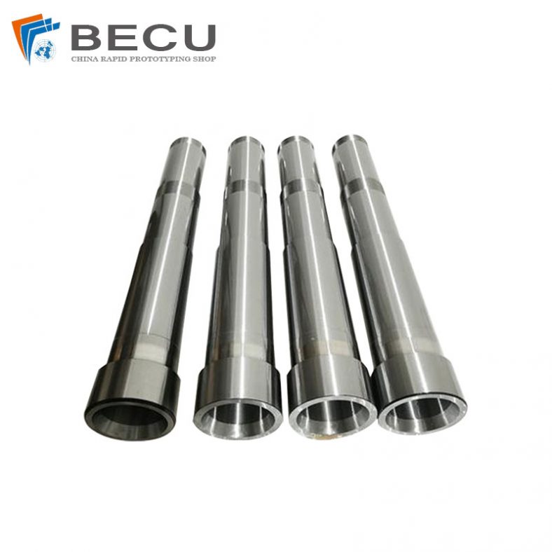
Large CNC Turning Inconel 625 Automobile Engine Camshafts
-
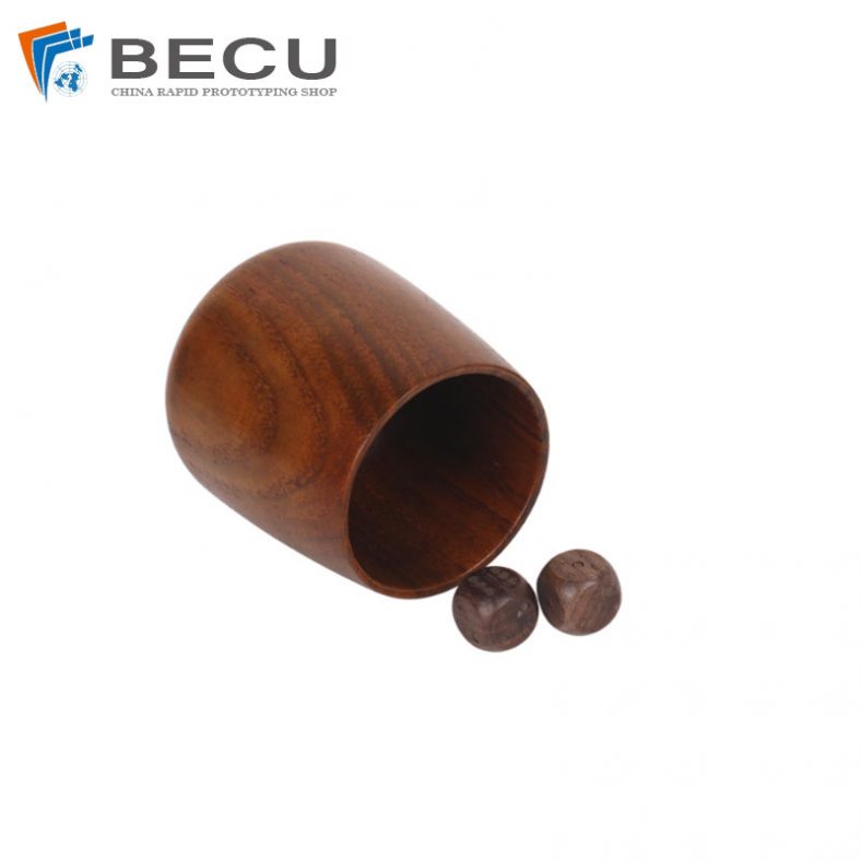
Precision Turning Solid Wood Dice
-

Custom Wood Chess Board, Sets And Pieces
-
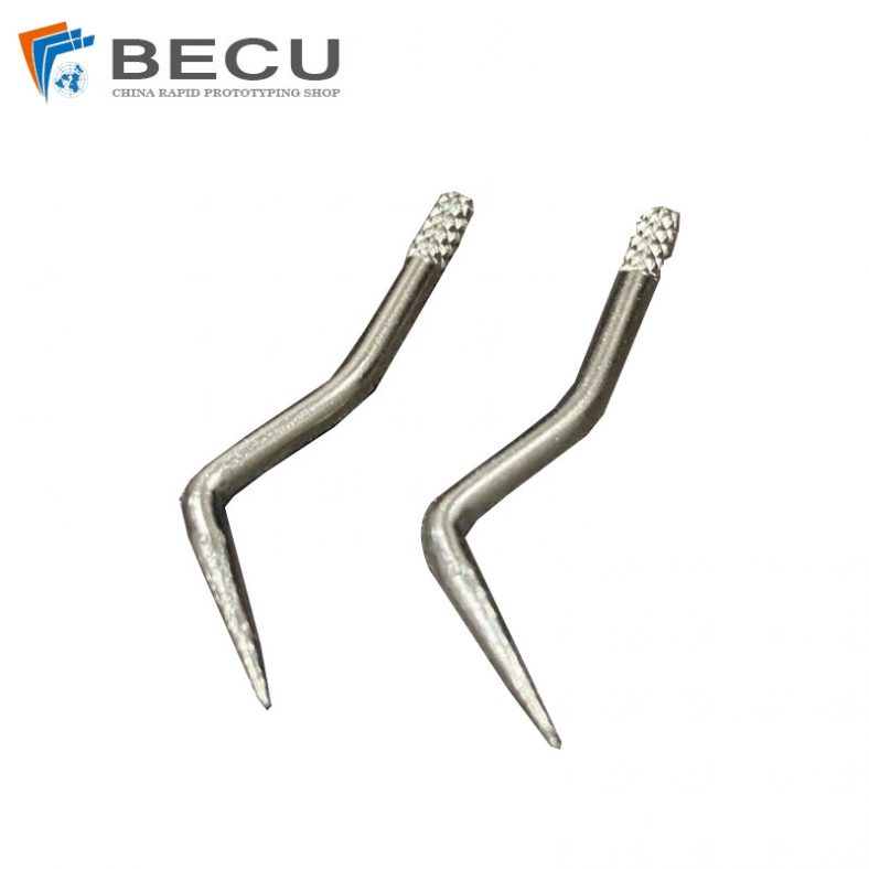
Swiss Machining And Bending 304 Hand Sewing Needle For Textile Machinery
-
Automatic Swiss Turning Stainless Steel 316L U-bolt
Online CNC Turning With China 9 Axis Lathing Company
Mastering the operation of a 9-axis lathe is a journey that requires patience, dedication, and a commitment to ongoing learning. With a solid foundation in the machine’s basics, programming and setup, advanced techniques, troubleshooting, and maintenance, you will be well-equipped to achieve remarkable results in your machining operations. Remember, constant practice, exploration of new strategies, and embracing the latest technological advancements are essential to stay ahead in today’s competitive manufacturing landscape. So, harness the power of the 9-axis lathe, push your boundaries, and unlock a world of possibilities in precision machining.
If you need custom 9 Axis Lathing parts with complex geometries, or get end-use products in the shortest possible time, Be-Cu.com is good enough to break through all of that and achieve your idea immediately. We operate over 150 sets of 3, 4, and 5-axis CNC machines and 9 axis cnc lathe, and offer 100+ different types of materials and surface finishes, guaranteeing quick turnaround and quality of one-off prototypes and production parts.Contact us via [email protected] to get free quote!