
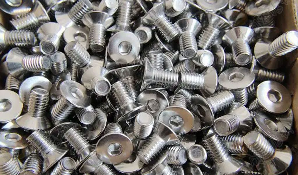
What Is A Machine Screw?
Machine screws are a type of fastener designed to be threaded into pre-tapped holes or used with nuts in various mechanical and industrial applications. They are typically smaller in diameter and shorter in length compared to other types of screws, such as wood screws.Machine screws have a uniform diameter along their entire length and are typically made of metal, such as steel or stainless steel. They have a threaded shaft with a blunt or flat end, and their heads come in various shapes, including flat head, round head, oval head, pan head, and truss head.
The head of a machine screw often has a slotted or Phillips drive for tightening with a screwdriver or a hex socket for use with a wrench or Allen key.These screws are commonly used in machinery, equipment assembly, automotive applications, electronics, and other industries where secure fastening is required. They provide reliable and durable connections and can be easily tightened or loosened when necessary.
Related Read: Metric & Imperial Bolt Dimensions Chart
The first time you read the label on a box of screws, you’ll probably come across a lot of confusing numbers that seemingly don’t make any sense.
But here’s the kicker:
I’m here to tell you that sizing the right screw doesn’t have to be guesswork anymore!
By the end of this guide, you’ll be able to confidently read a screw size chart and decipher all the measurements on a screw callout by yourself.
From metric and imperial size standards to all the other related intricacies, I’ve got it all covered below.
Let’s get started!
What’s The Difference Between Machine Screw And Bolt?
The main difference between machine screws and bolts lies in their intended applications and the way they are used.
Machine screws:
- Size: Machine screws are generally smaller in diameter and shorter in length compared to bolts.
- Fastening Method: Machine screws are threaded screws designed to be threaded into pre-tapped holes or used with nuts to create secure fastenings.
- Head Types: Machine screws typically have a variety of head types, such as flat head, round head, oval head, pan head, or truss head. These heads are designed for different applications and provide specific functionality.
- Thread Coverage: Machine screws usually have a full thread along their shaft, meaning the threads run the entire length of the screw.
Bolts:
- Size: Bolts are typically larger in diameter and longer in length compared to machine screws.
- Fastening Method: Bolts are used with nuts and are inserted through pre-drilled holes in two or more parts, with the nut tightened on the opposite side to secure the joint.
- Head Types: Bolts commonly have a hexagonal head (hex head) or square head, designed for tightening with a wrench or socket.
- Thread Coverage: Bolts usually have a partial thread, meaning the threads cover only a portion of the shaft, leaving unthreaded sections near the head.
Machine screws are smaller screws used for threaded fastenings with pre-tapped holes or nuts, while bolts are larger fasteners used with nuts and inserted through pre-drilled holes. Bolts typically have a partial thread and a specific head style for wrench or socket tightening, while machine screws have a full thread and a variety of head types for different applications.
The Types Of Machine Screws
There are several types of machine screws, each designed for specific applications. Here are some common types:
- Round Head Machine Screws: These screws have a rounded head with a flat bearing surface. They provide a low-profile appearance and are commonly used in applications where a flush or slightly raised finish is desired.
- Flat Head Machine Screws: Flat head screws have a flat top surface and a conical bearing surface. They are ideal for applications where the screw head needs to sit flush with the surface or be countersunk.
- Pan Head Machine Screws: Pan head screws have a rounded, slightly domed head with a flat bearing surface. They offer a larger bearing area and are suitable for applications where a greater clamping force is required.
- Oval Head Machine Screws: Oval head screws have an oval-shaped head with a flat bearing surface. They are often used when a low-profile appearance is desired, similar to round head screws, but with a more decorative look.
- Truss Head Machine Screws: Truss head screws have a low-profile, wide head with a rounded top and a flat bearing surface. They provide a larger load-bearing area and are commonly used in applications where a strong joint is required.
- Cheese Head Machine Screws: Cheese head screws have a cylindrical head with a flat bearing surface and a rounded top. They are named for their resemblance to a wheel of cheese. These screws are often used in applications where a decorative or vintage look is desired.
- Phillips Head Machine Screws: Phillips head screws have a cross-shaped indentation on the head, designed to be used with a Phillips screwdriver. They provide good torque transfer and are widely used in various applications.
- Slotted Head Machine Screws: Slotted head screws have a single straight slot on the head, allowing for tightening or loosening using a flat-blade screwdriver. They are a traditional type of screw head but are less common compared to Phillips or other drive types.
These are just a few examples of the most commonly used machine screw types. Other specialized types, such as hex head screws or socket head screws, are also available to suit specific applications and requirements.The Unified Screw Thread System and ISO Metric Screw Thread System are two major systems to classify the machine screws, based on inches and millimeters, separately. Machine screw sizes chart for the most common UNF (Unified Fine) and UNC (Unified Coarse) in The Unified Screw Thread System are provided at BE-CU.COM. As a professional CNC machining services supplier, we can produce custom screws and other fasteners for your specific applications.
How To Read A Screw Chart
Reading a screw chart involves understanding the various columns and information provided. Here are the key elements typically found in a screw chart and how to interpret them:
- Screw Size: The screw size column lists the numerical or alphanumeric designations for different screw sizes. This can include numbers (#0, #1, #2, etc.), letters (A, B, C, etc.), or a combination of both.
- Thread Size: The thread size column provides the thread designation, which indicates the number of threads per inch (TPI) or the thread pitch in metric measurements. For example, 20 TPI or 1.25 mm pitch.
- Major Diameter: The major diameter column lists the nominal or approximate diameter of the screw thread. It represents the outer diameter of the threaded portion of the screw.
- Minor Diameter: The minor diameter column provides the nominal or approximate diameter of the unthreaded portion or the root diameter of the screw.
- Head Diameter: The head diameter column specifies the diameter of the screw head. This measurement is crucial when considering the fit of the screw head in the corresponding hole or recess.
- Head Height: The head height column indicates the height or thickness of the screw head. This measurement is essential when determining how much the screw head will protrude or sit flush with the surface.
- Length: The length column indicates the overall length of the screw, including the threaded and unthreaded portions. This measurement helps determine the appropriate screw length for the desired application.
By understanding and interpreting the information provided in these columns, you can identify the appropriate screw size, thread size, dimensions, and length required for your specific project or application. It’s essential to refer to the specific screw chart you are using, as different charts may vary in format and details provided.
Unified National Thread Sizes With Their Dimensions
| Screw Size | Major Diameter (inch) | Threads per Inch (TPI) | Minor Diameter (inch) | Head Diameter (inch) | Head Height (inch) |
|---|---|---|---|---|---|
| #0 | 0.060 | 80 | 0.051 | 0.120 | 0.040 |
| #1 | 0.073 | 64 | 0.062 | 0.137 | 0.043 |
| #2 | 0.086 | 56 | 0.074 | 0.154 | 0.046 |
| #3 | 0.099 | 48 | 0.086 | 0.173 | 0.049 |
| #4 | 0.112 | 40 | 0.098 | 0.190 | 0.052 |
| #5 | 0.125 | 40 | 0.110 | 0.207 | 0.055 |
| #6 | 0.138 | 32 | 0.122 | 0.224 | 0.058 |
| #8 | 0.164 | 32 | 0.146 | 0.258 | 0.067 |
| #10 | 0.190 | 24 | 0.170 | 0.293 | 0.076 |
| 1/4″ | 0.250 | 20 | 0.220 | 0.375 | 0.094 |
| 5/16″ | 0.312 | 18 | 0.280 | 0.469 | 0.109 |
| 3/8″ | 0.375 | 16 | 0.330 | 0.562 | 0.125 |
| 1/2″ | 0.500 | 13 | 0.450 | 0.750 | 0.156 |
| 5/8″ | 0.625 | 11 | 0.570 | 0.938 | 0.188 |
| 3/4″ | 0.750 | 10 | 0.680 | 1.125 | 0.219 |
| 1″ | 1.000 | 8 | 0.900 | 1.500 | 0.250 |
US (Inch) Screw Sizes With Decimal And Metric Equivalents
Here is a reference chart showing common US (inch) screw sizes with their decimal equivalents and corresponding metric equivalents:
| US Screw Size (Inch) | Decimal Equivalent (Inch) | Metric Equivalent (mm) |
|---|---|---|
| #0 | 0.060″ | 1.524 mm |
| #1 | 0.073″ | 1.854 mm |
| #2 | 0.086″ | 2.184 mm |
| #3 | 0.099″ | 2.515 mm |
| #4 | 0.112″ | 2.845 mm |
| #5 | 0.125″ | 3.175 mm |
| #6 | 0.138″ | 3.505 mm |
| #8 | 0.164″ | 4.166 mm |
| #10 | 0.190″ | 4.826 mm |
| 1/4″ | 0.250″ | 6.350 mm |
| 5/16″ | 0.313″ | 7.938 mm |
| 3/8″ | 0.375″ | 9.525 mm |
| 7/16″ | 0.438″ | 11.113 mm |
| 1/2″ | 0.500″ | 12.700 mm |
| 9/16″ | 0.563″ | 14.288 mm |
| 5/8″ | 0.625″ | 15.875 mm |
| 3/4″ | 0.750″ | 19.050 mm |
| 7/8″ | 0.875″ | 22.225 mm |
| 1″ | 1.000″ | 25.400 mm |
Please note that this chart provides approximate metric equivalents for common inch screw sizes. The metric equivalents are rounded to the nearest millimeter. It’s important to consult specific engineering or screw reference guides for precise conversions and measurements, as there may be variations and tolerances depending on the specific screw standard and application requirements.
US Machine Screw Diameters Chart
| Screw Diameter (inch) | Thread Size (Threads per Inch) |
|---|---|
| #0 | 80 |
| #1 | 64 |
| #2 | 56 |
| #3 | 48 |
| #4 | 40 |
| #5 | 40 |
| #6 | 32 |
| #8 | 32 |
| #10 | 24 |
| 1/4″ | 20 |
| 5/16″ | 18 |
| 3/8″ | 16 |
| 7/16″ | 14 |
| 1/2″ | 13 |
| 9/16″ | 12 |
| 5/8″ | 11 |
| 3/4″ | 10 |
| 7/8″ | 9 |
| 1″ | 8 |