
In CNC milling machines, the coordinate system and origin play a crucial role in defining the positions and movements of the cutting tool relative to the workpiece. Understanding and properly setting up the coordinate system and origin are essential for accurate and efficient machining. Here’s a detailed explanation of the CNC milling machine coordinate system and origin:
Coordinate System
The coordinate system in a precision CNC milling machine is a three-dimensional reference system that defines the machine’s workspace. It consists of three mutually perpendicular axes – X, Y, and Z. These axes are defined as follows:
- X-Axis: The X-axis is the horizontal axis that runs from left to right, parallel to the machine’s table or work surface.
- Y-Axis: The Y-axis is the horizontal axis that runs from front to back, perpendicular to the X-axis.
- Z-Axis: The Z-axis is the vertical axis that runs from the bottom to the top, perpendicular to both the X and Y axes.
Coordinate Origin
The coordinate origin, also known as the zero point or reference point, is a specific location on the workpiece where the three axes intersect. It serves as the starting point for all tool movements and positions during CNC machining. The origin point is typically set to a known and easily accessible location on the workpiece, making it convenient to reference during setup and toolpath programming.
Setting the Coordinate Origin: The process of setting the coordinate origin is known as “workpiece zero” or “work zero” setup. It involves several steps:
- Workpiece Setup: Place the workpiece securely on the machine’s table and ensure it is aligned with the machine’s axis. Use clamps, vises, or fixtures to hold the workpiece firmly in place.
- Tool Setup: Install the cutting tool in the CNC milling machine’s spindle. Ensure the tool is properly mounted and aligned with the machine’s axis.
- Reference Point Selection: Choose a specific reference point on the workpiece surface that will serve as the origin. This point should be easily identifiable and measurable.
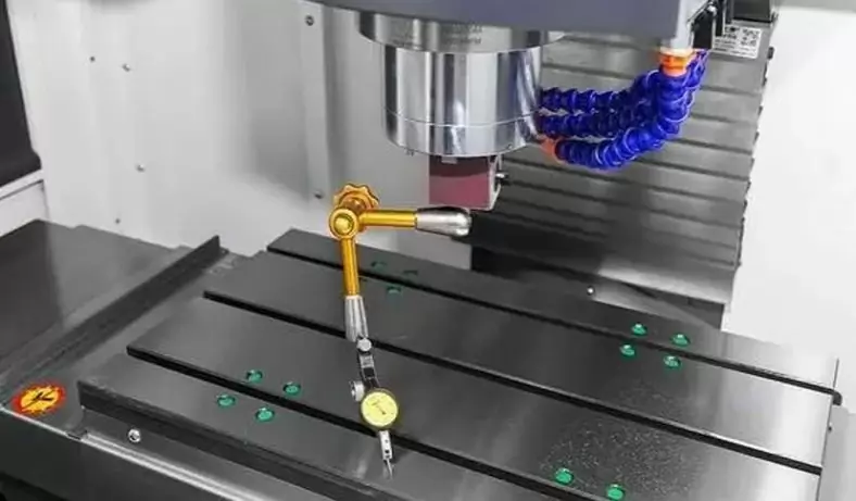
- Tool Touch-Off: Use a touch probe or edge finder to locate the reference point accurately. The touch probe allows the machine to measure the tool’s position relative to the workpiece surface, while the edge finder detects the workpiece’s edge.
- Zero Setup: Move the machine’s axes to bring the cutting tool precisely to the reference point. At this position, set the X, Y, and Z coordinates to zero. This establishes the coordinate origin for the workpiece.
Work Coordinate System (WCS)
In addition to the machine coordinate system, CNC milling machines often support multiple work coordinate systems (WCS). A WCS allows the operator to set additional origins for specific features or operations on the workpiece without changing the machine’s coordinate system. This feature is useful when machining multiple features on different parts of the workpiece without re-referencing the coordinate system each time.
In summary, the coordinate system and origin in a CNC milling machine provide the fundamental framework for defining tool positions and movements relative to the workpiece. Properly setting the coordinate origin is essential for accurate machining and ensures that the CNC milling machine follows the programmed toolpaths accurately and consistently.
Program Origin And Workpiece Coordinate System
The program origin (Pmgr.m Or.gin) is represented by W, which is the geometric reference point defined by the programmer on the workpiece during the CNC programming process, and is sometimes called the workpiece origin (Part Origin).
The origin of the workpiece is generally selected at a reference position that is convenient for measurement or tool setting, and at the same time, it is convenient for programming and calculation. Pay attention to the following points when selecting the position of the workpiece origin.
- The origin of the workpiece should be selected on the dimension datum of the part pattern, so as to facilitate the calculation of the coordinate value and make the programming simple.
- Try to choose the machined surface with higher precision to improve the machining accuracy of the machined parts.
- For symmetrical parts, the origin of the workpiece is generally set on the center of symmetry.
- For general parts, the origin of the workpiece is usually set at a corner of the outer contour of the piece.
- When the origin of the workpiece is in the Z-axis direction, it is generally set on the surface of the workpiece.
When programming, generally select a certain point on the workpiece as the program origin, and use this origin as the origin to establish a new coordinate system, that is, the T-piece coordinate system (programming coordinate system). Determine the position of the starting point of the tool relative to the origin of the workpiece coordinate system.
Clamp The Original Electric Clamp Origin
It is often used in CNC machine tools or T centers with rotary or oscillating worktables. It is generally a fixed point on the T table of the machine tool, such as the rotary center. The offset between the clamping origin and the reference point of the machine tool can be stored in the origin offset register (Or.E, n Offset Register) of the CNC system after the measurement, for the calculation of the origin offset of the CNC system.
Additional Motion Coordinates
Generally, X, Y, z are called the main coordinates or the first coordinates. If there are second or third sets of coordinates parallel to the first coordinates, they are designated as U, v, W and P, Q, R, respectively. That is, additional motion coordinates.
Relationship Between Machine Tool Coordinate System And Workpiece Coordinate System
The relationship between the machine tool coordinate system and the T-piece coordinate system. The X, Y, Z coordinate system is the machine tool coordinate system, and the X, Y’, Z’ coordinate system is the lower part coordinate system.
At Be-cu.com,we use advanced equipment to offer you Unparalleled precision for producing metal and plastic machining parts
- We combine the latest CNC milling and turning processes with proprietary technology to deliver high quality, on-demand parts.
- Our team of engineers and machinists program the equipment to optimize cutting time, surface finish, and final tolerance to meet your design specifications
- We specialize in cnc precision machining, single part prototyping, short to medium production runs, manufacture parts on time, every time, so you can stay ahead of schedule
- CNC machining can create very similar parts to series parts. It is often more efficient and faster than other rapid prototyping technologies for the manufacture of a quantity of prototypes between 1 and 10 parts . We also recommend CNC machining for parts with large sizes (greater than 600 mm).
Contact Us ([email protected]) Now for your Custom CNC Machining, We are your best online cnc machining and rapid prototyping services choice!