
In the automotive body manufacturing process, tailor-welded blank stamping technology has been widely used due to its many advantages, such as reducing body mass, improving body assembly accuracy, increasing body stiffness, and reducing body stamping and assembly costs.At present, the parts produced by tailor-welded blanks mainly include A, B, C pillars, door inner panels, longitudinal beams, floors, etc..
Due to the difference in thickness and material properties, the forming properties of tailor-welded blanks are significantly different from those of traditional single-material sheets, which are manifested in material properties and deformation characteristics.
Simulation is an important method to study the forming of TWBs with different thicknesses. Scholars at home and abroad have done a lot of research on it. An Zhiguo et al. used the method of incremental forming to simulate the forming process of TWB with different thicknesses, and studied the influence of process parameters on the formability.
In order to improve the formability of tailor-welded blanks, a clamping tool is used to control the movement of the weld seam in the stamping simulation process. Zheng Guangwen et al. used four weld models to simulate the forming process of tailor-welded blanks to verify the practicability of weld models. Zhou Jie et al and SH Chang[6]et al. analyzed the effect of different plate thickness ratios and weld positions on springback prediction.
None of the above studies have considered the feature of the differential thickness step on the mold surface when the differential thickness plate is actually formed. Therefore, this paper builds a simulation model that is consistent with the actual forming mold to improve the accuracy of the simulation calculation, and compares it with the test results.
Forming Characteristics Of Differential Thickness Tailor Welded Blanks
Features of blanks and molds
Tailored blanks refer to the welding of two or more flat sheets of different thicknesses. Due to the difference in thickness, the thin plate and the thick plate have a plane in a common plane during the welding process, which is convenient for welding. Due to the thickness difference between the thin plate and the thick plate, there will be a height difference on the other side of the thick plate and the thin plate. This height difference will cause the problem that the thin-side blank cannot fit the mold surface during the stamping process of the die that is not adjusted. Therefore, the profile surface of the differential thickness plate mold also needs to be processed with a thick profile surface, and a step is formed on the profile surface, so as to realize the complete fit of the mold and the sheet metal.
Characteristics of Weld Line Formation
During the stamping process, due to the plastic deformation of the blank, the weld line on the blank is deformed and offset. On the one hand, it is required that the deviation between the weld line of the formed part and the weld line of the product design is controlled within a small range; Small gap area for people. Therefore, it is required that the step position on the mold profile should match the position of the weld line after the actual forming. At the same time, it should be noted that when the step position of the mold changes, the plastic deformation of the blank will be affected, thereby affecting the position and shape of the actual weld line, and the two will affect each other. Therefore, it is necessary to determine the position of the blank weld line and the step position of the mold during simulation modeling.
Construction Of The Simulation Model
Construction of billet and mold ladder
In the common stamping simulation modeling method, the neutral layer is used for the sheet material to replace the position of the intermediate layer. For Tailored Blanks, the intermediate layers of two sheets with different thicknesses are not actually on the same plane. Therefore, one of the plates should be offset by a certain distance t during the construction of the sheet metal model, as shown in formula (1).
The tailor-welded model after offset is shown in Figure 1, which is consistent with the actual tailor-welded blank. After the tailor-welded blanks are accurately modeled, the tooling also needs to be adjusted accordingly. Since most stamping parts require a smooth shape, in the actual stamping process of TWBs with different thicknesses, in order to ensure a smooth outer surface, the stepped side corresponds to the blank holder and punch.
Therefore, the blank holder and The surface of the punch needs to be partially offset to achieve the fit of the sheet and the mold. The distance between the blank holder and the thin side or thick side of the punch is Dd.
Determination Of Mold Step Curve
The determination of the mold step curve is essentially the determination of the blank weld line. After the stamping simulation, the deformed weld line is obtained, and then the mold step curve is constructed accordingly. Since the formed weld line should be as close as possible to the product design weld line, it is necessary to optimize the iterative calculation of the blank weld line. Therefore, there is always a certain deviation between the weld line after forming and the design weld line.
The process of obtaining the blank weld line is shown in Figure 3. First build a complete stamping process model and extend the design weld line to the binder surface. Then carry out stamping simulation calculation, discretize the extended design weld line into points, obtain its corresponding position on the blank by grid mapping method and fit it into a curve, compare the relative deviation of the weld line after forming, and analyze the blank. The welding seam line on the top is adjusted accordingly, and the process is repeated until the welding seam line is basically consistent with the design welding seam line after forming. At this time, the blank welding seam line obtained by optimization is a curved welding seam, and the least square method needs to be converted into a straight welding seam. Then, according to the overall deviation and end deviation of the straight weld line and the design weld line after forming, the corresponding overall offset and rotation adjustment are carried out, so that the design weld line after the final forming basically runs through the weld lines obtained by the simulation forming. The step curve of the mold can be obtained by offsetting the weld line obtained by the final forming to the thick side by a safe distance of about 10mm.
Computing Examples
In this paper, a type of tailor-welded blank model of the inner panel of a car door is used as the test object, and the method in this paper is verified by comparing the two intuitive data of the movement of the weld line and the springback. The material thickness is 1.4 mm, 0.7 mm, The design model and process model are shown in Figure 4.
According to the design of the weld line optimization, after the blank weld line is obtained, the simulation model is constructed in the traditional method and the accurate modeling method proposed in this paper for calculation, and the actual stamping is performed. The obtained parts are shown in Figure 5.
Figure 6 shows the deviation of the weld line after simulation and calculation in two different ways and the actual obtained weld line relative to the product design weld line. It can be seen that the accurately modeled simulation result weld line is more consistent with the real weld line.
When analyzing the accuracy of springback prediction, this paper uses a typical U-shaped part, and designs a trimming line on the door inner panel model (Figure 7). The width of the trimming line is 60mm, and the left and right are symmetrical.
After using the same springback simulation method, the results shown in Figure 8 are obtained. After analysis, using the modeling method of accurate model, the maximum springback of the thick side of the U-shaped piece is 0.35mm, and the maximum springback of the thin side is 1.077mm. Using the traditional modeling method, the maximum springback of the thick side of the U-shaped piece The rebound amount is 0.285mm, and the maximum rebound amount on the thin side is 0.251mm.
The actual stamping part is laser-cut to obtain a U-shaped part as shown in Figure 9(a), which is scanned in reverse, as shown in Figure 9(b).
Figure 10 shows the comparison results between the springback data obtained by the traditional modeling and simulation method and the actual stamping parts. It can be seen that most of the deviations on the thick side are -0.151~0.652mm, and most of the deviations on the thin side are 0.151~1.154mm.
Figure 11 shows the comparison results of the springback data obtained by the accurate modeling and simulation method with the actual stamping parts. After the middle features are aligned, the deviation of the thick side is -0.158~0.158mm, and the deviation of the thin side is larger. Comparing the two results at -0.158~-0.658 mm, it can be clearly seen that the springback prediction data of the accurate stamping process model is more accurate. close to the actual part shape.
At the same time, measure the distance between the two ends of the U-shaped piece to compare the size of the springback deformation, as shown in Figure 12.
Measure the traditional modeling springback simulation results, the accurate modeling springback simulation results, and the distance d between the two ends of the actual part, and take the equidistant distance from one side to the other to obtain the curve in Figure 13. It can be seen that the precise modeling and simulation method is closer to the actual measured value, indicating that the precise modeling and simulation method is more accurate than the traditional modeling and simulation method in the prediction of springback.
Conclusion
The forming of TWB with differential thickness is obviously different from that of ordinary steel plate. When constructing the simulation model, it is necessary to pay attention to the method of single-sided flushing the billet during tailor-welding, and corresponding offset when meshing the billet.
At the same time, it is necessary to take into account the characteristics of the mold for differential plate forming. When building the simulation model, on the one hand, a mold with a stepped profile should be established for mesh division, and on the other hand, the stepped curve of the mold surface should be accurately calculated. To ensure that the stepped curve of the mold surface can adapt to the final part weld line. Experiments and related data analysis show that the accuracy of accurate modeling and simulation calculation is higher.
China Sheet Metal Fabrication Company
Sheet fabrication services for mild steel, high strength low alloy (HSLA) steel, cold/hot rolled steel, galvanized steel, stainless steel, aluminum, copper and brass. Capable of fabricating parts up to 12 ft. length and +/-0.001 in. tolerance. Various capabilities include contract manufacturing,custom stamping,edge rolling, forming,top laser cutting, roll bending and welding. Finishing and secondary services such as hardware installation, tapping, deburring, cleaning, heat treating, plating, anodizing and painting available. Sheet Metal Prototype and low to high volume production runs offered.
Suitable for commercial/residential architectural, aluminum brake shape parts, wall panel systems, brackets, general flashings, rails, call button plates and ship building component parts.If you want a specific material to be used in the sheet metal fabrication process, don’t hesitate to contact us!
-
Stainless Steel Sheet Metal Fabrication
-
Aluminum Sheet Metal Fabrication
-
Copper Sheet Metal Fabrication
-
Brass Sheet Metal Fabrication
-
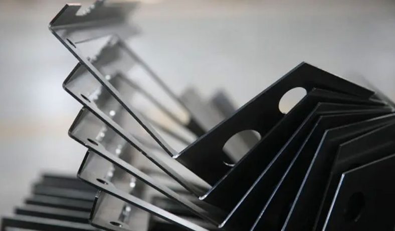
Steel Sheet Metal Fabrication
-
Titanium Sheet Metal Fabrication
-
Galvanized Steel Sheet Metal Fabrication
-
Mild Steel Sheet Metal Fabrication
-
Bronze Sheet Metal Fabrication
Our Sheet Metal Fabrication Applications
Be-Cu prototype offers custom sheet metal fabrication for creating structures, machines, and parts that includes:
Our Case Studies Gallery Of Sheet Metal Fabrication Parts
If you need custom Sheet Metal Fabrication parts in China from a trusted supplier, look no further. Professional service from 10 to 100000+ parts,Whether you want a small series production or large quantities,Be-Cu Prototype scale precision Sheet Metal Fabrication services according to our customers needs, including pipe,plate and tube cutting. Contact us to see how we can help you! Get a quote today!
-
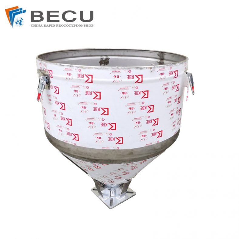
Sheet Metal Fabrication Injection Molding Machine Hopper
-
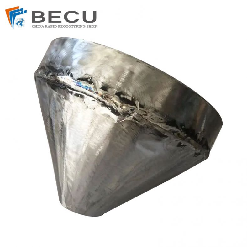
Sheet Metal Fabrication Funnel For Agricultural Machinery
-
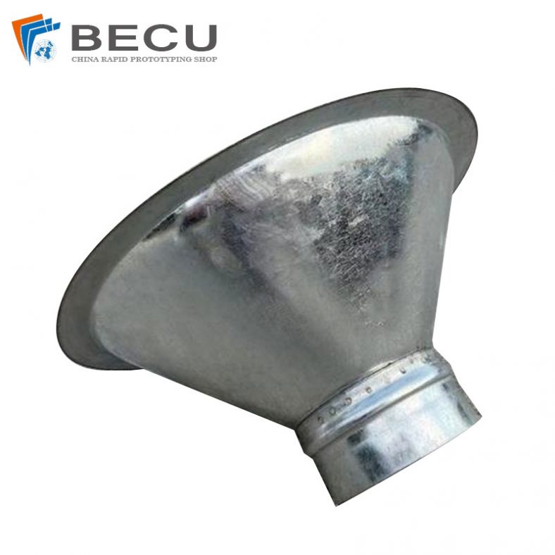
Sheet Metal Fabrication Galvanized Spiral Air Duct
-
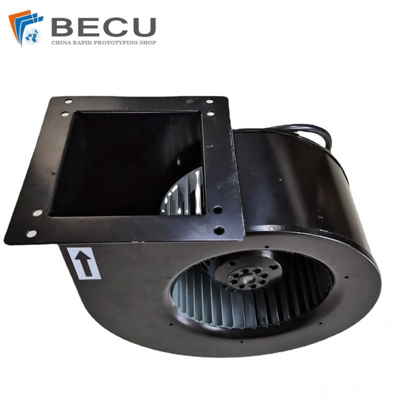
PCS Fan Ductwork Sheet Metal Housing
-
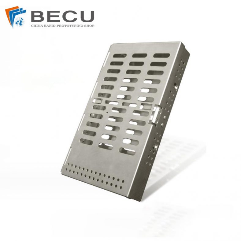
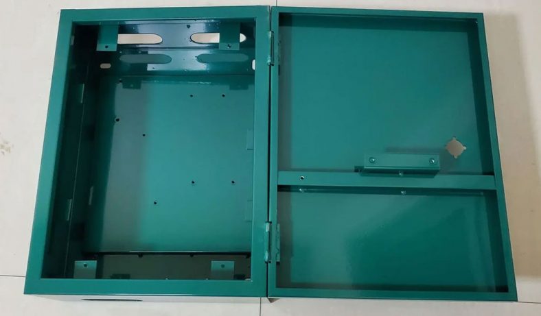
Custom Sheet Metal Surgical Instrument Sterilization Box For Beauty Salon
-
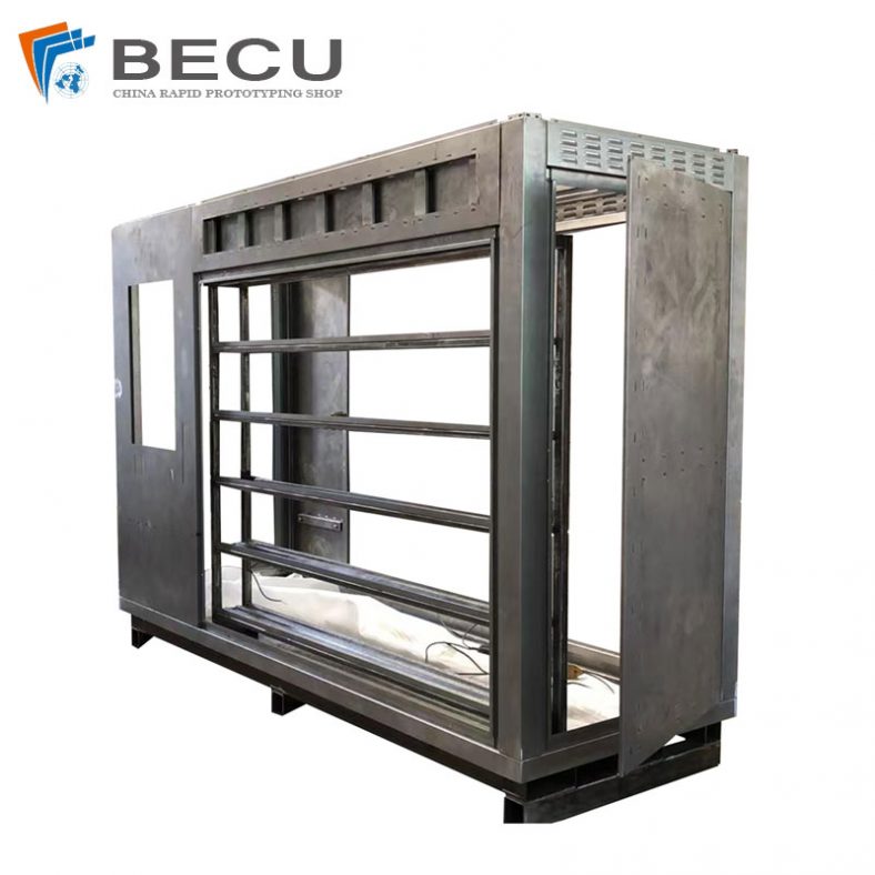
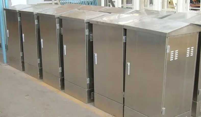
Precision Fabrication Green Energy EV Charging Station Cabinet
-
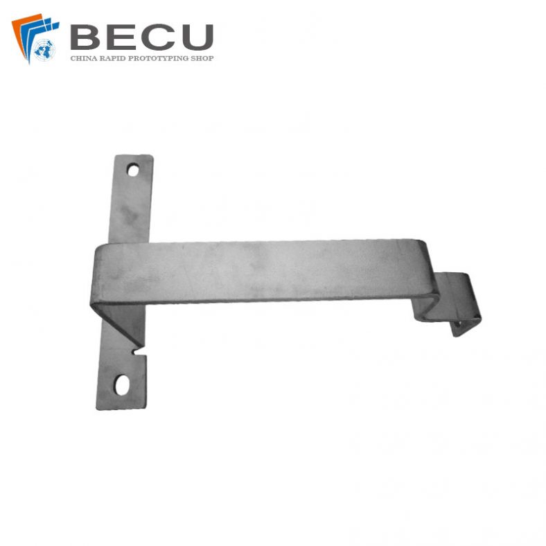
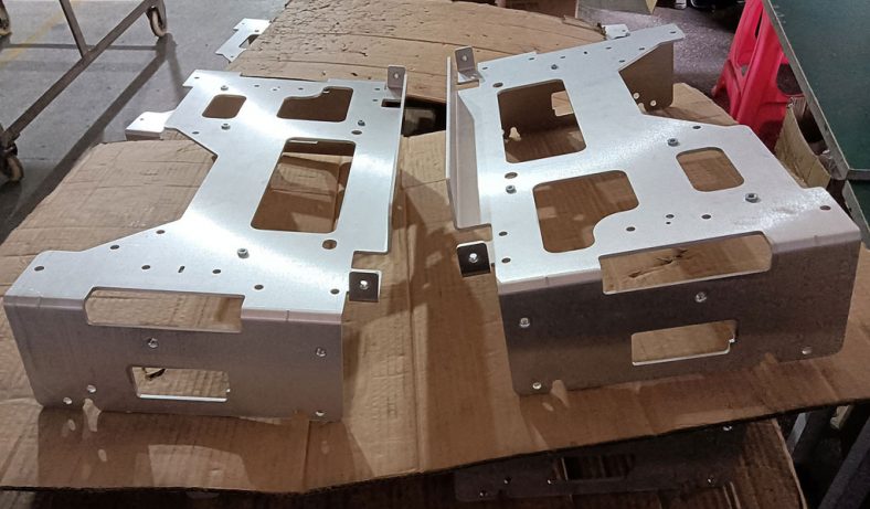
TA1TA2 Alloy Sheet Metal Manufacturing Machinery Support Parts
-
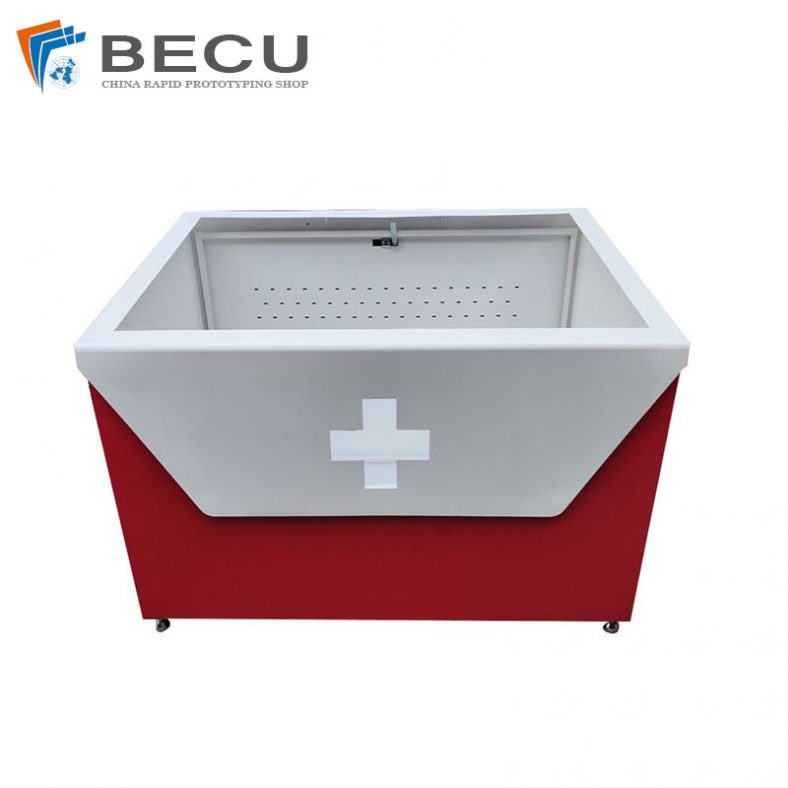
Sheet Metal Fabrication Aluminum 5052 Medical Box For Fire Fighting