
With the increasing adoption of electric vehicles (EVs) and renewable energy storage systems, the demand for high-performance and safe power batteries has grown substantially. A critical component of any battery system is the Battery Management System (BMS), which plays a crucial role in monitoring, controlling, and protecting the battery pack. Ensuring functional safety in the development process of the BMS is of utmost importance to prevent potential hazards and enhance the overall performance and reliability of the battery system. This article explores the development process of a power battery BMS with a focus on functional safety considerations.
Overview of Battery Management Systems (BMS)
A Battery Management System (BMS) is an essential electronic control unit responsible for overseeing the charging and discharging processes, cell balancing, state-of-charge (SOC) estimation, temperature management, and safety protection of a power battery pack. The BMS ensures the optimal performance, longevity, and safety of the battery system, making it a critical component in various applications, including EVs, grid storage systems, and portable devices.
Development Process of Power Battery BMS Involving Functional Safety
The development process of a power battery BMS involving functional safety can be divided into several key phases:
- 1. Safety Requirements Analysis: The process begins with a thorough safety requirements analysis to identify potential hazards, assess risks, and define the necessary functional safety requirements. This phase involves understanding the application and its operating conditions, identifying possible failure modes, and defining safety goals.
- 2. System Architecture Design: The next step is to design the system architecture, including hardware and software components. The architecture should be developed in a way that ensures redundancy, fault tolerance, and fail-safe mechanisms.
- 3. Hazard and Risk Analysis: Conduct a hazard and risk analysis to identify and evaluate potential safety risks. This analysis involves assessing the consequences of possible system failures and implementing safety measures to mitigate risks.
- 4. Safety Integrity Level (SIL) Determination: Assign Safety Integrity Levels (SILs) to different components based on their criticality and safety impact. SIL is a measure of the effectiveness of a safety function in reducing risks, ranging from SIL1 (lowest) to SIL4 (highest).
- 5. Hardware and Software Development: Develop the BMS hardware and software components in compliance with functional safety requirements and SILs. This involves implementing redundancy, self-checking mechanisms, and safety features to achieve the required safety integrity.
- 6. Verification and Validation: Thoroughly verify and validate the BMS design through simulations, testing, and validation against safety requirements. This includes testing the BMS under normal operating conditions and various fault scenarios.
- 7. Safety Validation and Certification: The BMS should undergo an independent safety validation process to ensure compliance with functional safety standards. This may involve third-party assessments and certification.
- 8. Production and Operation: After successful validation and certification, the BMS is ready for production and operation. Continuous monitoring and maintenance are necessary to ensure ongoing functional safety compliance throughout the lifecycle of the battery system.
Challenges and Future Developments
Developing a power battery BMS involving functional safety is a complex task that presents several challenges:
- 1. Integration Complexity: Integrating safety features into the BMS without compromising its performance, size, or cost is a challenging task that requires careful design and engineering.
- 2. Data Security: Ensuring the security of the BMS data is crucial, as any unauthorized access or manipulation of data can compromise safety and performance.
- 3. Evolving Standards: Functional safety standards are continuously evolving, and developers must stay updated with the latest requirements and best practices.
- 4. Scaling for High-Voltage Systems: Scaling functional safety to high-voltage battery systems presents additional challenges, as higher voltage levels demand more stringent safety measures.
The development process of a power battery BMS involving functional safety is a critical aspect of ensuring the reliable and safe operation of power battery packs in various applications. Implementing the necessary safety measures, adhering to international standards, and conducting thorough verification and validation are essential to achieve the desired functional safety levels. As the demand for electric vehicles and renewable energy storage systems continues to grow, the focus on functional safety in BMS development will become even more critical to safeguarding users, the environment, and the efficient functioning of power battery systems.
The Definition Of Functional Safety
Functional safety: There is no unreasonable risk of hazards arising from failure of electrical and electronic systems. Therefore, the first priority of functional safety development is to avoid unacceptable risks. As a vehicle component, BMS generally obtains the FSR (Function safety requirements) at the conceptual stage from the Safety Goal at the vehicle level during functional safety development, and then analyzes the TSR (Technical safety requirements) at the electrical and electronic level from the FSR at the conceptual stage. Finally analyze the BMS
software and hardware functional safety requirements. The figure below is a schematic diagram of the ISO26262 development process.
Overview Of Power Battery BMS Involving Functional Safety
In the ISO26262 standard, we distinguish between two types of failures, errors and failures: random and systematic failures. Systematic failures can be avoided by appropriate methods at the design stage, while random failures can only be reduced to an acceptable level. Systematic or even random failures will occur in hardware, while software failures are more systematic failures. First, according to the security objectives, determine the security level. For each hazard event, according to its exposure probability E, controllability C, severity S three elements, determine its ASIL level.
According to the development process of ISO26262, starting from requirements, including conceptual design, system design, hardware design, software design, and finally production release, after-sales maintenance, corresponding functional safety requirements are put forward, which covers the entire life cycle of the car , so as to ensure that the functions of automotive electronic products are safe and reliable, and even if the function fails, it will not cause danger. As the key to new energy vehicles, BMS has more and more complex functional requirements. BMS must have basic sampling functions such as voltage, current, and temperature, and at the same time supervise the operation process of the battery in real time.
Temperature and other protection functions, and SOP, SOC, SOH prediction, fault diagnosis, balanced control, thermal management, fast and slow charging management, etc. Applying the ISO26262 standard requirements to the development of BMS will greatly improve the security of BMS.
If the BMS is regarded as a safety element out of context (independent safety unit), the independent safety unit means that other elements in the vehicle are temporarily ignored during the product development cycle. According to the Saftety Goal provided by the OEM, the BMS developer supplier derives the Saftety Requirements according to the Satety Goal, followed by the system design, hardware design, software design and so on.
As a part of the whole vehicle, some functions on the whole vehicle will interact with the battery system, and the results of their actions must be considered from the perspective of related items.
BMS is developed in accordance with the development practice of automotive electronics and electrics, according to the main process of the V model, and the OEM will participate in the testing part on the right side of the V model.
The Definition Of Related Items
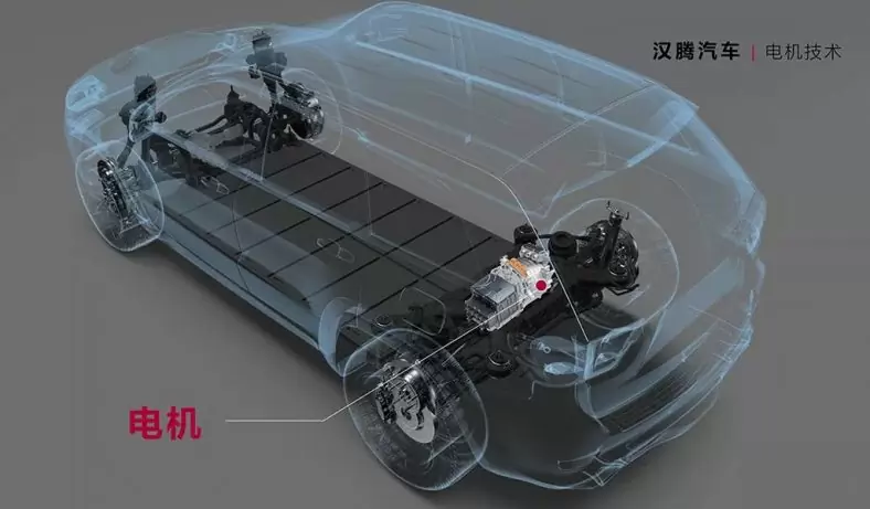
The battery high voltage system is mainly composed of junction box, module, battery balance connector, high voltage connector module, BMS, etc. The BMS collects data such as voltage and temperature through sensors for processing, calculates the SOC/SOH of the battery, and diagnoses faults. At the same time, information exchange is carried out with the VCU through the vehicle CAN. When defining the relevant items, analyze the battery system components and define the scope of the functional safety analysis. The following figure is the structure and principle block diagram of the battery system. The functional safety goals undertaken by BMS are obtained at the level of vehicle-related items. On this basis, the development and verification of BMS products are carried out.
Development Process
First identify the hazardous event. According to different working conditions, different driving habits and weather conditions, the most likely hazardous events are analyzed, and the hazardous events are assigned to various functional departments of the system. In ISO26262-3, Hazrad analysis can be confirmed by methods such as brainstorm, DFMEA, etc. Taking the monomer overcharge hazard event as an example, the level of the hazard event is determined according to the three elements of the ASIL level. The table below is a simple HARA analysis of cell overcharge. In this table, if the thermal runaway of the battery cell causes the vehicle to catch fire on an urban road, the ASIL Level is C; when the vehicle is at a low speed, the ASIL Level is A.
List All Possibilities Of Function Failure Due To Malfunction;
Summarize all functions and faults, differentiate them by operating mode, and form a matrix of hazardous events. Through hazard analysis and risk assessment, functional safety objectives for hazard events are defined. Combine the safety levels of the same hazard event in different scenarios, and use the highest functional safety level as the safety level of the hazard event. In order to avoid the occurrence of hazardous events, a safety goal is formed.
The safety objectives can be considered from the perspective of avoiding the occurrence of hazardous events, and can also be proposed from the perspective of avoiding the occurrence of failures. For example, a safety goal is proposed for the hazard of over-discharge causing an internal short-circuit battery to catch fire. From the perspective of avoiding hazards, the safety goal is proposed to prevent over-discharge from causing a short-circuit battery to catch fire. From the perspective of avoiding failure, the safety goal is proposed to avoid temperature limit failures. The ASIL level of the safety target is the highest level of the hazardous event.
After the safety goal is derived, some safety-related parameters also need to be specified. These parameters include: operation mode, fault tolerance time, safe state, functional redundancy, etc.
The second step is to determine the functional safety requirements FSR. Each safety objective defines at least one functional safety requirement. Although a functional safety requirement can cover more than one safety objective, each FSR inherits the highest ASIL from the associated SG. Through a layered approach, safety objectives are derived from risk assessment and hazard analysis, and functional safety requirements are derived from the safety objectives. The functional safety level of the FSR, which automatically inherits the highest level of the safety target.
The third step is to refine the technical safety requirements (TSR) from the functional safety requirements (FSR). Throughout the development life cycle, the technical safety requirements are the technical requirements to implement the concept of functional safety. The intent is from the detailed single-level functional safety requirements to System-level security technical requirements. The following table shows the transformation of functional safety requirements into technical safety requirements, which is only for reference in the process.
The fourth step, the system design stage, the system and subsystems need to implement the technical security requirements defined above, and need to reflect the security detection and security mechanisms defined above. The technical safety requirements should be assigned to the system design elements, and the system design should complete the technical safety requirements. Regarding the realization of the technical safety requirements, the following issues should be considered in the system design, define the system architecture, assign TSR to hardware and software, and define Software and hardware interface HIS. The hardware-software interface specification shall specify the interaction of hardware and software, and be consistent with the concept of technical security, and shall include components of hardware devices that are controlled by software and hardware resources to support software operation.
System design, three principles are given in the standard: modularity, appropriate granularity and simplicity. For different security levels, emphasis is placed on design considerations that focus on different aspects.
Technical safety requirements, either directly or after further refinement, are assigned to hardware and software.
After the system design is complete, design verification also needs to be considered. The higher the functional safety goal, the more inclined to the way of physical verification.
The fifth step is the functional safety design of the hardware system. The detailed security requirements of the hardware come from the TSR, the system architecture and the system boundary HSI. According to ISO 26262-8 Chapter 6.4.2 Hardware safety requirements specification shall include each hardware requirement related to safety, and hardware safety requirements shall be verified in accordance with ISO 26262-8 Chapter 6 and Chapter 9 requirements to provide evidence. Hardware design can start with a hardware functional block diagram. All elements and internal interfaces of the hardware block diagram should be displayed. Then a detailed circuit diagram is designed and verified, and finally the possible failures of the hardware architecture are verified by methods such as deductive method (FTA) or inductive method (FMEA). For the BMS system, the battery pack voltage sensor is a very important sensor, so it is necessary to analyze the different failure modes of the battery pack voltage sensor for different ASIL levels. Some failure modes can be prevented by hardware requirements, and some failure modes can be separated into software requirements to prevent.
The design of each technical safety requirement is closely related to the actual product function, technological development level, and supplier level, etc., and is the starting point for product differentiation of different manufacturers. The specific implementation of the product has its own different ideas. Some do not apply the safety mechanism, and directly require the components to improve their own functional safety level; some choose to add a monitoring mechanism or provide a redundant design with different principles to improve the functional safety level.
The hardware design verification principles recommended by the standard are as follows:
The sixth step, software system design. Software development in the automotive industry generally follows the V model, with the development process on the left and the testing process on the right. The BMS software development process is basically consistent with the V model of the software development process recommended in Part VI of ISO26262, as shown in the figure below. In the design of software architecture, the maintainability and testability of the software need to be considered. In the automotive industry, software should consider maintainability during the entire product cycle, and at the same time consider the ease of implementation of software architecture design testing. In the ISO 26262 standard, testing is a very important aspect, and any design should take into account at the same time. Ease of testing. So far, the design and development of the product has been completed.
The software architecture design principles recommended by the standard are as follows:
The error handling mechanism recommended by the software architecture level standard is as follows:
- BMS design based on functional safety_Han Yuping
- Research on the evaluation method of safety integrity level in line with ISO_26262 standard_He Bo
- Overview of the development of the concept stage of BMS based on ISO26262_Tianxing
- Research on BMS design method based on functional safety and its reliability_Inkai
- GB∕T 34590.3-2017 Road Vehicle Functional Safety Part 3: Concept Stage
- GB∕T 34590.4-2017 Road Vehicle Functional Safety Part 4: Product Development: System Level
- GB∕T 34590.5-2017 Road Vehicle Functional Safety Part 5: Product Development: Hardware Level
- GB∕T 34590.6-2017 Road Vehicle Functional Safety Part 6: Product Development: Software Level

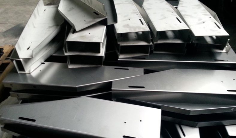
China Sheet Metal Fabrication Company
Sheet fabrication services for mild steel, high strength low alloy (HSLA) steel, cold/hot rolled steel, galvanized steel, stainless steel, aluminum, copper and brass. Capable of fabricating parts up to 12 ft. length and +/-0.001 in. tolerance. Various capabilities include contract manufacturing,custom stamping,edge rolling, forming,top laser cutting, roll bending and welding. Finishing and secondary services such as hardware installation, tapping, deburring, cleaning, heat treating, plating, anodizing and painting available. Sheet Metal Prototype and low to high volume production runs offered.
Suitable for commercial/residential architectural, aluminum brake shape parts, wall panel systems, brackets, general flashings, rails, call button plates and ship building component parts.If you want a specific material to be used in the sheet metal fabrication process, don’t hesitate to contact us!
-
Stainless Steel Sheet Metal Fabrication
-
Aluminum Sheet Metal Fabrication
-

Copper Sheet Metal Fabrication
-

Brass Sheet Metal Fabrication
-
Steel Sheet Metal Fabrication
-

Titanium Sheet Metal Fabrication
-
Galvanized Steel Sheet Metal Fabrication
-

Mild Steel Sheet Metal Fabrication
-

Bronze Sheet Metal Fabrication
Our Sheet Metal Fabrication Applications
Be-Cu prototype offers custom sheet metal fabrication for creating structures, machines, and parts that includes:

Our Case Studies Gallery Of Sheet Metal Fabrication Parts
If you need custom Sheet Metal Fabrication parts in China from a trusted supplier, look no further. Professional service from 10 to 100000+ parts,Whether you want a small series production or large quantities,Be-Cu Prototype scale precision Sheet Metal Fabrication services according to our customers needs, including pipe,plate and tube cutting. Contact us to see how we can help you! Get a quote today!
-
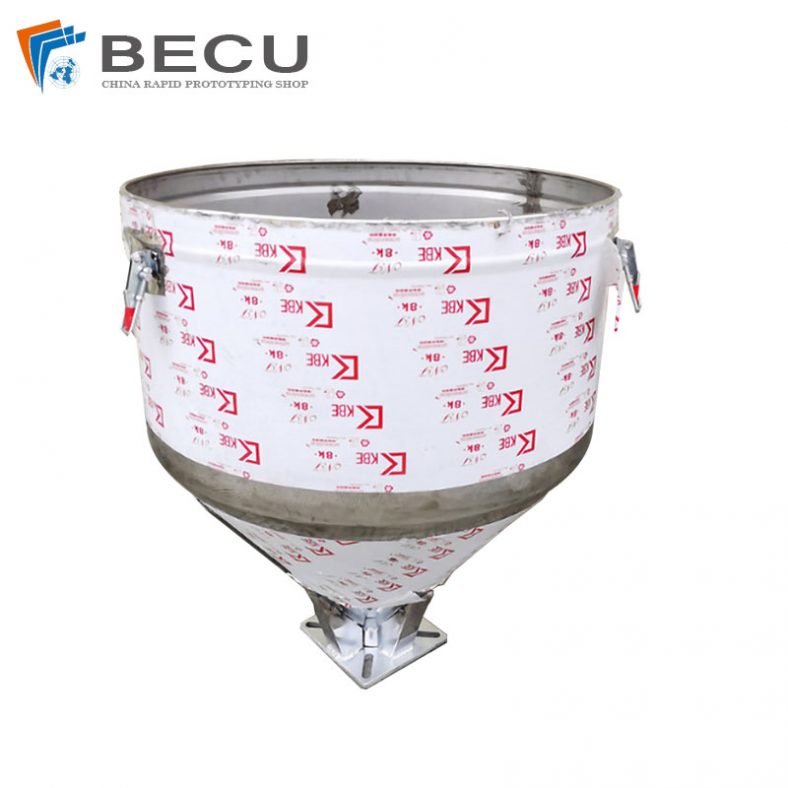
Sheet Metal Fabrication Injection Molding Machine Hopper
-
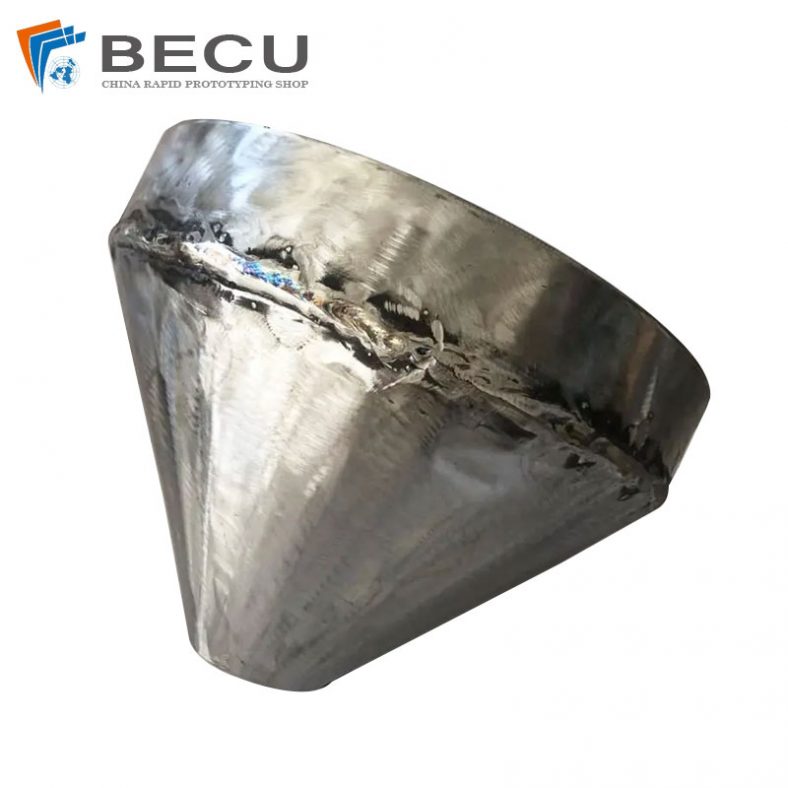
Sheet Metal Fabrication Funnel For Agricultural Machinery
-
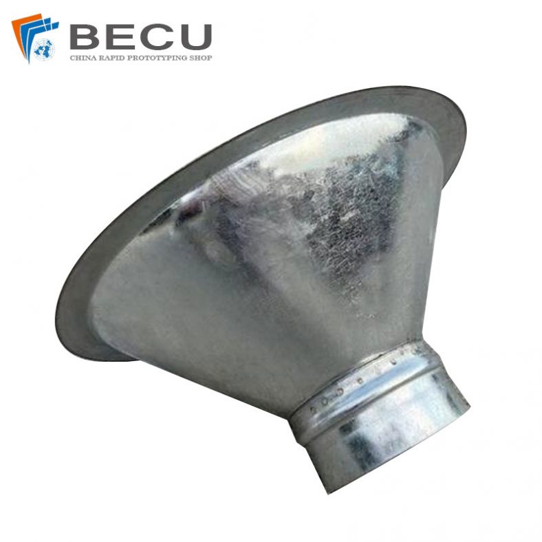
Sheet Metal Fabrication Galvanized Spiral Air Duct
-
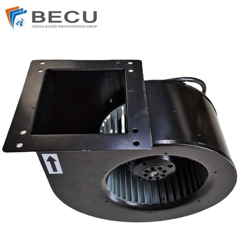
PCS Fan Ductwork Sheet Metal Housing
-
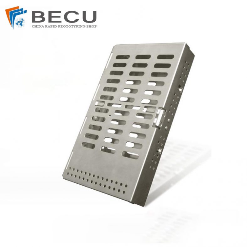
Custom Sheet Metal Surgical Instrument Sterilization Box For Beauty Salon
-
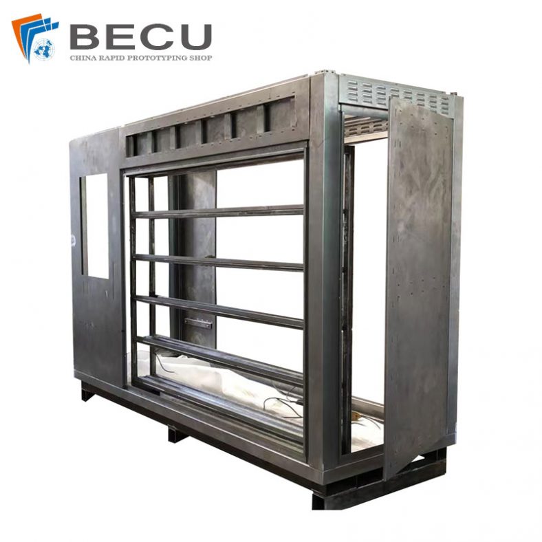
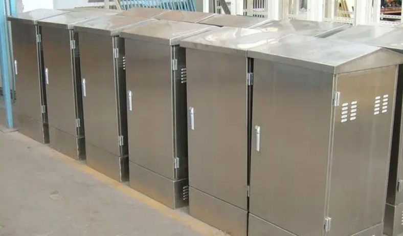
Precision Fabrication Green Energy EV Charging Station Cabinet
-
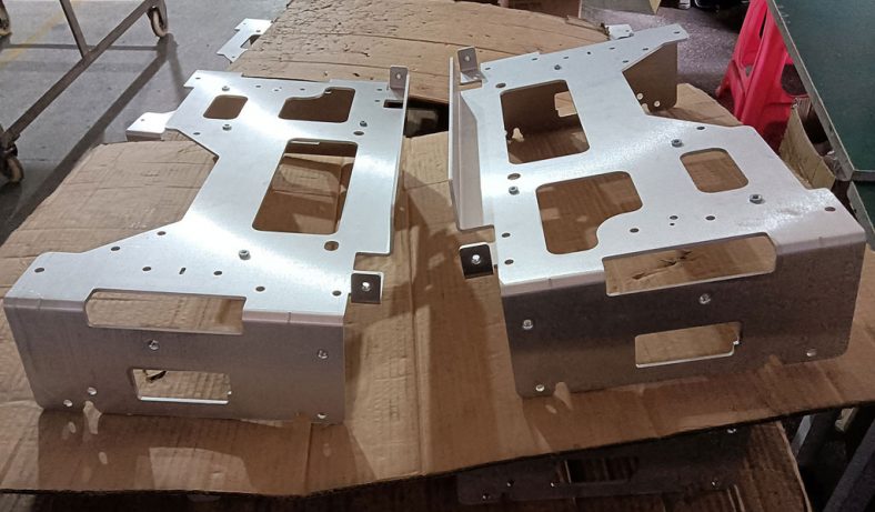
TA1TA2 Alloy Sheet Metal Manufacturing Machinery Support Parts
-
Sheet Metal Fabrication Aluminum 5052 Medical Box For Fire Fighting