
With the rapid development of the automobile industry, the requirements for the quality of automobile products are getting higher and higher. In particular, the requirements for the surface of the product are getting higher and higher. Due to the characteristics of the trimming process itself, iron filings will be generated when the trimming conditions are not good, and some iron filings will enter the mold cavity, and these will enter the mold cavity. The iron filings will damage the mold while crushing the workpiece.
View More Products:
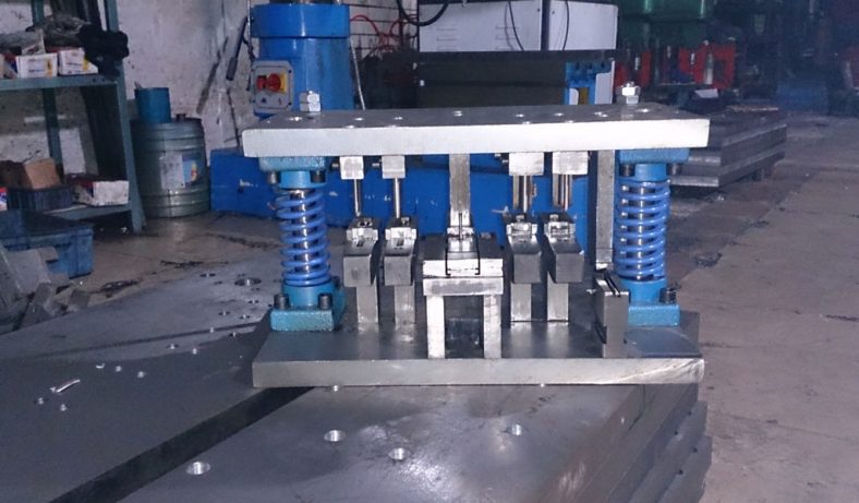
The trimming of stamping die and dealing with iron filings typically involves cleaning and maintaining the die to ensure the quality and precision of stamped parts.
Analyze the data and feedback from maintenance and production to identify areas for improvement in die design or maintenance procedures.By following these steps and maintaining a proactive approach to die maintenance and cleanliness, you can minimize the issues associated with iron filings and ensure the longevity and precision of your stamping die.
2 Reasons For Iron Filings
1.Blanking Process
The blanking change curve is shown in Figure 3, from which one can see several stages of the blanking process.
- AB segment: the elastic deformation stage of the sheet.
- BC segment: the plastic deformation stage of the sheet.
- Point C: It is equivalent to the ultimate strength of the material, that is, the maximum value of the punching force. When the stress in the material reaches the shear strength, the material begins to crack.
- CD segment: the crack propagates to the fracture stage of material separation.
- DE section: The punch overcomes the frictional force and pushes the blanking piece (or scrap) out of the punch.
2.Analysis Of The Causes Of Iron Filings
- Point A—σ1 is the radial compressive stress caused by the punch side pressure and sheet bending; σ2 is the composite tangential stress of the compressive stress caused by sheet bending and the tensile stress caused by side pressure; σ3 is the convex The transverse tensile stress caused by die pressing is shown in Fig. 4.
- Point B – subject to three-way compressive stress, which is caused by the pressing of the punch and the bending of the sheet.
- Point C—σ1 is the tensile stress generated by the tensile action of the sheet, and σ2 is the compressive stress generated by the extrusion of the sheet.
- Point D—the radial tensile stress σ1 and the tangential tensile stress σ2 and σ3 caused by the bending of the sheet metal are the axial compressive stress generated by the die extrusion of the sheet metal.
- Point E—σ1 is the stress generated by the combination of the tensile stress caused by the bending of the sheet and the compressive stress caused by the pressure on the side of the die, and σ2 is the axial tensile stress caused by the pressing of the punch. In general, point E is mainly dominated by tensile stress.
From the stress states at points A, B, C, D, and E, it can be seen that the hydrostatic stress (compressive stress ball tensor) on the end faces of the punch and die (points B and D) is higher than that of the side faces (A, point E). In addition, due to the bending of the material, the sheet on the side of the punch is compressed in both directions, and the sheet on the side of the die is stretched in both directions, so the hydrostatic stress near the edge of the punch is higher than that near the edge of the die. high. Therefore, punching cracks are first generated at the point E of the sidewall of the die edge where the hydrostatic stress is the lowest, and then at the point A of the sidewall of the punch edge.
If the blanking gap is reasonable, the main cracks from point A and point E overlap; but if the gap is unreasonable, a third crack will be generated in the upper and lower cracked parts, as shown in Figure 5.
Fig. 5 Crack generation and development process a—the first crack occurs b—the first crack stops developing c—the second and third cracks are generated d—the main crack is generated burr: the burr is formed from the plastic deformation stage After the bright band, the punch continues to descend, the plastic deformation increases, and the material hardening in the deformation zone increases, causing the material to start to crack near the cutting edge. Due to the existence of the gap between the convex and concave die, it is not just at the cutting edge, but at points A and E not far from the cutting edge, and in addition to the shear deformation caused by the extrusion of the material by the punch, it also occurs at points A and E not far from the cutting edge. Bending and tensile deformation will occur, so burrs are generated at this time. When the material is in the shearing stage (cracking stage), the lowering of the punch causes the burr to continue to stretch and finally remain on the blanked part.
Generation of iron filings: When burrs are generated, if the gap is unreasonable, the third crack between the upper and lower cracks will cause some burrs to detach from the material and form trimming iron filings.
3.Hazards Of Trimming Iron Filings
When the automatic stamping line is produced, the quality of the parts can only be checked at the end of the automatic line, and the quality status of the parts in the stamping process cannot be detected and processed immediately like a manual operation line. When quality defects are often found, there are already many parts in the production process. Among them, the quality problem with the greatest impact is that during the trimming process of the workpiece, due to the relative movement of the upper and lower molds, a negative pressure is generated inside the mold cavity, and the relatively positive air flow outside the mold cavity sucks the iron filings generated by trimming into the mold cavity. , pollutes the cavity surface, and has to stop the assembly line to clean the cavity, which not only affects the quality of the parts, but also greatly affects the production efficiency, and even affects the accuracy of the equipment and molds, causing potential safety hazards.
Measures To Prevent And Reduce Iron Filings
1.Rationalization Of Edge Clearance
- When the gap is too small, the cracks that initially occur near the edge of the die will point to the high-pressure stress area under the punch. Therefore, the growth of this crack is inhibited, it cannot reach the punch edge, and becomes a stagnant crack. When the crack opening is quite large, a part of the material between the two cracks will be cut for the second time as the punching progresses. Cut, and then squeezed into the cavity by the punch. Due to the extrusion effect of the die edge, a second bright band is formed on the cross-section, and a torn burr and interlayer are formed between the two bright bands, as shown in Figure 6a.
- When the gap is too large, the actual gap will be larger because the sheet material has formed a larger rounded band before the bright band is formed. In this case, because the upper and lower cracks are staggered by a certain distance and the fillet zone is large, the verticality of the section is poor, as shown in Fig. 6b. Also, due to different processing conditions, cracks may not necessarily occur at the upper and lower cutting edges at the same time, so sometimes the material may be separated by a crack at one cutting edge. When the crack starts from the tip of one cutting edge and extends to the side of the other cutting edge, it leaves a large burr on the section. Therefore, when the gap is too large, the bright band on the section decreases, and the rounded corners, burrs and slopes become larger.
- When the clearance is reasonable, the cracks generated at the upper and lower cutting edges will form a line during the punching and cutting process, as shown in Figure 6c. In this case, the obtained blanking part has a larger bright band, while the rounded band, burr and slope are smaller, the surface is relatively flat, and the cross-section and plane quality can achieve the desired effect.
It can be seen from the above analysis that if the gap is too large or too small, the cross-sectional quality of the blanking parts is poor, and only when the gap is reasonable can the cross-sectional quality of the blanking parts meet the standard.
2.Trimming Process Optimization
- The most commonly used trimming scheme is the one that produces the most trimming iron filings, as shown in Figure 7. These types of molds are most prone to trimming iron filings and often make scrap discharge difficult.
- Trim the edges twice or more in the process, using the scrap knife structure/no scrap knife structure, as shown in Figure 8. For this type of mold structure, since the trimming is done in two times, the waste is surrounded by pressing material during the first trimming. Under the condition of reasonable cutting edge clearance, there will be basically no burrs and iron filings, and the quality of the parts is stable.
- Integral trimming secondary slitting and discharging. The first working stroke of the mold trims the part as a whole, and the second working stroke cuts off the last trimming waste for discharge. This type of mold is also more suitable for automatic production, which is easy to discharge and the cutting edge clearance is reasonable. There will be burrs and trimming iron filings, as shown in Figure 9, and such structures are currently widely used on top covers.
3.Scrap Knife Arrangement And Structure Optimization
- Under the premise of the allowable size of waste conveying equipment and mold structure discharge, the arrangement of scrap knives can be minimized. For example, the Shanghai Volkswagen scrap knives standard clearly states that scrap knives should be avoided as much as possible.
- Optimization of scrap knife structure. Comparing the two, in fact, there are only two differences between the scrap knives in South Korea: one is that only about 5mm of plane is left on the cutting edge, and the rest are all beveled, so that iron filings will not accumulate, as shown in Figure 10 and Figure 11. . The second is that scrap knives use forgings, not castings, where iron filings may be brought into the die cavity.
4.Rotary Scrap Knife
It is difficult for traditional scrap knives to separate trimming and scrap cutting, especially at the junction of scrap knives and trimming edges, where trimming iron filings are most likely to be generated.Shanghai Volkswagen requires that a rotary scrap knife must be used for the cover scrap knife, which can achieve trimming and scrapping.The separation of the two actions of material cutting can greatly reduce the generation of iron filings, as shown in Figure 12.Structure description:
- The position of the bolt center point must be higher than the starting point.
- The ratio of the two lever arms should be L1 : L2=1 : 1.
- The swing blade device should be 5mm above the center line of the rotation point, and the angle X should be 2° larger than the swing angle Y of the swing blade.
5.Optimize The Mold Structure, Pay Attention To Proper Emptying
For molds produced by automation or high-speed lines, due to the relatively fast production cycle, if the mold structure is unreasonable, negative pressure will be generated inside the mold cavity, and the relatively positive air flow outside the mold cavity will suck the iron filings generated by trimming into the mold cavity. This results in a pressure injury on the surface of the product. It can also be seen at the production site that although Japanese and Korean molds also have iron filings during trimming, they rarely bring into the mold cavity to crush the parts, while domestic molds often have iron filings brought in. A large part of the reason for the situation of the mold cavity is that the domestic molds are either not emptied, or “empty and not working”.
6.Add Air Blowing Device For Improvement
Using the slider angle to control the compressed air The working process of the auxiliary trimming mold blowing device is as follows: by installing the blowing pipe between the upper mold surface insert and the scrap cutter, and using the press slider angle to control the compressed air valve switch, so as to blow Remove the iron filings from the scrap cutter, as shown in Figure 13.
Conclusion
To sum up, trimming iron filings has a great relationship with trimming die structure, cutter block arrangement, trimming cutter block material, hardness, verticality, clearance, production environment, waste discharge and so on. The unreasonable arrangement of scrap knives in the mold design stage and the failure of production personnel and tooling maintenance personnel in the mass production stage to operate in strict accordance with the production and mold maintenance operation instructions will produce iron filings. In addition, during production, the height of the mold is too low, the waste is not cleaned in time, and foreign objects are pressed into the surface of the mold, causing the upper and lower molds to be misaligned, gnawing the cutting edge, and producing iron filings. Therefore, reasonable mold structure and cutting edge clearance and standard operation process and implementation play a vital role in eliminating and reducing iron filings from trimming and improving the service life of the mold.
China Sheet Metal Fabrication Company
Sheet fabrication services for mild steel, high strength low alloy (HSLA) steel, cold/hot rolled steel, galvanized steel, stainless steel, aluminum, copper and brass. Capable of fabricating parts up to 12 ft. length and +/-0.001 in. tolerance. Various capabilities include contract manufacturing,custom stamping,edge rolling, forming,top laser cutting, roll bending and welding. Finishing and secondary services such as hardware installation, tapping, deburring, cleaning, heat treating, plating, anodizing and painting available. Sheet Metal Prototype and low to high volume production runs offered.
Suitable for commercial/residential architectural, aluminum brake shape parts, wall panel systems, brackets, general flashings, rails, call button plates and ship building component parts.If you want a specific material to be used in the sheet metal fabrication process, don’t hesitate to contact us!
-
Stainless Steel Sheet Metal Fabrication
-
Aluminum Sheet Metal Fabrication
-
Copper Sheet Metal Fabrication
-
Brass Sheet Metal Fabrication
-
Steel Sheet Metal Fabrication
-
Titanium Sheet Metal Fabrication
-
Galvanized Steel Sheet Metal Fabrication
-
Mild Steel Sheet Metal Fabrication
-
Bronze Sheet Metal Fabrication
Our Sheet Metal Fabrication Applications
Be-Cu prototype offers custom sheet metal fabrication for creating structures, machines, and parts that includes:
Our Case Studies Gallery Of Sheet Metal Fabrication Parts
If you need custom Sheet Metal Fabrication parts in China from a trusted supplier, look no further. Professional service from 10 to 100000+ parts,Whether you want a small series production or large quantities,Be-Cu Prototype scale precision Sheet Metal Fabrication services according to our customers needs, including pipe,plate and tube cutting. Contact us to see how we can help you! Get a quote today!
-
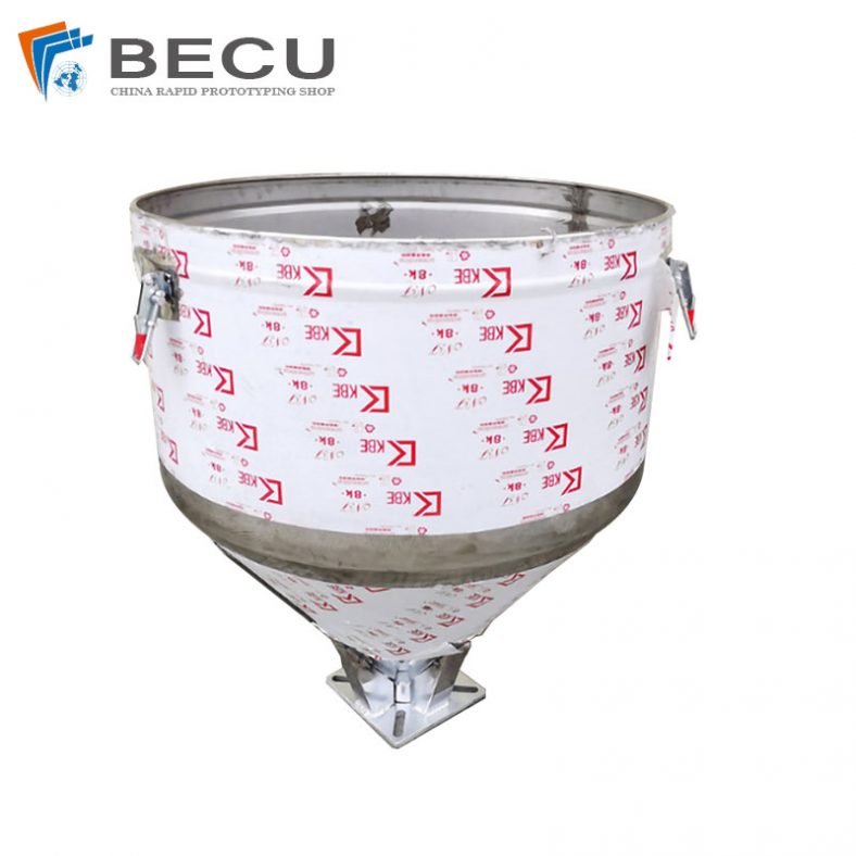
Sheet Metal Fabrication Injection Molding Machine Hopper
-
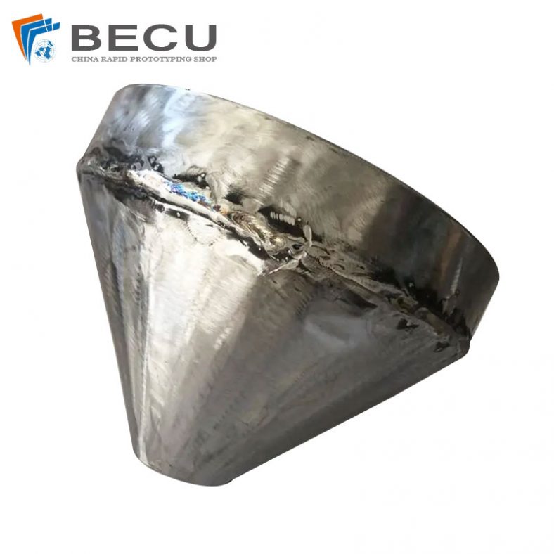
Sheet Metal Fabrication Funnel For Agricultural Machinery
-
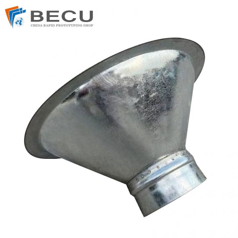
Sheet Metal Fabrication Galvanized Spiral Air Duct
-
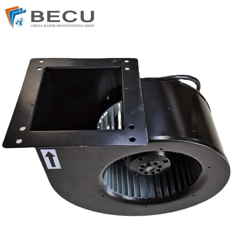
PCS Fan Ductwork Sheet Metal Housing
-
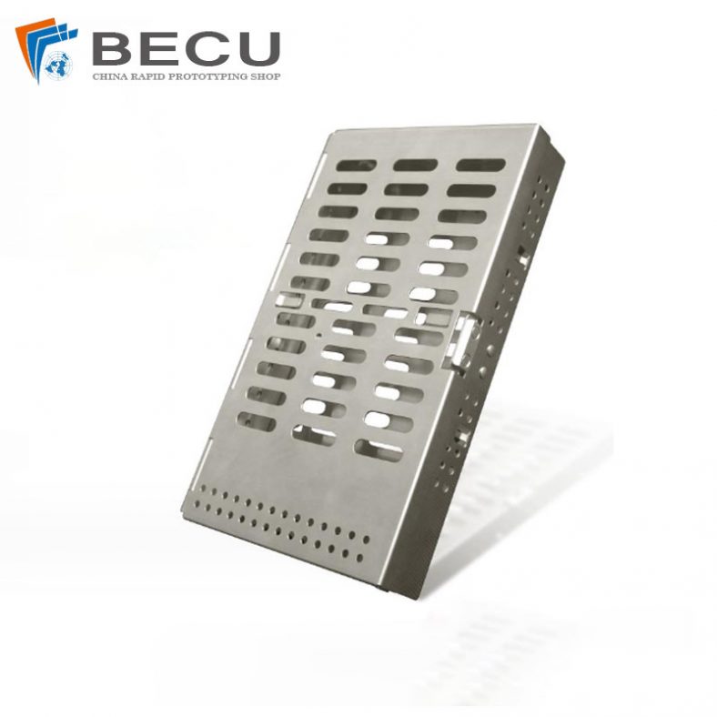
Custom Sheet Metal Surgical Instrument Sterilization Box For Beauty Salon
-
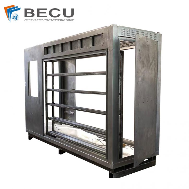
Precision Fabrication Green Energy EV Charging Station Cabinet
-
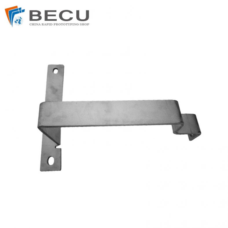
TA1TA2 Alloy Sheet Metal Manufacturing Machinery Support Parts
-

Sheet Metal Fabrication Aluminum 5052 Medical Box For Fire Fighting