
Welding is a fabrication process that joins materials, typically metals or thermoplastics, by causing coalescence through the application of heat, pressure, or both. While welding is a critical technique in industries ranging from construction to aerospace, the process is not immune to imperfections. These imperfections, commonly referred to as welding defects or weld discontinuities, are irregularities in the weld that may compromise the integrity, strength, or functionality of the welded joint. Understanding welding defects is essential for ensuring the reliability and safety of welded structures. This article provides a comprehensive exploration of welding defects, including their definitions, diagrammatic representations, classifications, causes, and remedies, with detailed comparative tables to enhance clarity.
Definition of Welding Defects
A welding defect is any irregularity or deviation from the desired weld characteristics that may affect the performance of the welded joint.
According to the American Welding Society (AWS), a defect is a discontinuity that exceeds acceptable limits as defined by applicable welding codes or standards, such as AWS D1.1, ASME Section IX, or ISO 5817. Weld discontinuities, on the other hand, are imperfections that may or may not be considered defects depending on their size, location, and impact on the weld’s performance.
Welding defects can manifest as surface irregularities, subsurface flaws, or metallurgical changes in the weld or heat-affected zone (HAZ). They can reduce the mechanical properties of the weld, such as tensile strength, ductility, or fatigue resistance, and may lead to catastrophic failures in critical applications like pressure vessels, pipelines, or aircraft components. The study of welding defects involves identifying their nature, assessing their severity, and implementing corrective measures to ensure compliance with industry standards.
Importance of Studying Welding Defects
The significance of understanding welding defects lies in their potential to compromise the structural integrity of welded assemblies. In industries such as oil and gas, where pipelines must withstand high pressures, or in aerospace, where components are subjected to extreme stresses, even minor defects can lead to leaks, fractures, or complete failure. By studying welding defects, engineers, welders, and inspectors can:
- Ensure compliance with safety and quality standards.
- Minimize the risk of costly repairs or replacements.
- Enhance the longevity and reliability of welded structures.
- Improve welding techniques and process controls to prevent recurrence.
This article delves into the various types of welding defects, their causes, and the methods used to mitigate them, providing a thorough resource for professionals and researchers in the field.
Diagram of Welding Defects
Visual representation is a powerful tool for understanding welding defects. A typical diagram of a welded joint highlights the weld bead, the heat-affected zone (HAZ), and the base metal, with annotations indicating common defects such as cracks, porosity, or incomplete fusion. Below is a textual description of a standard welding defect diagram, as a detailed schematic would typically accompany such an article.
In a cross-sectional view of a butt weld, the weld bead appears as a semi-elliptical region joining two base metal plates. The HAZ surrounds the weld bead, showing a gradient of microstructural changes due to heat exposure. Defects are marked as follows:
- Cracks: Linear discontinuities, often appearing as jagged lines within the weld bead or HAZ.
- Porosity: Small, spherical voids scattered throughout the weld metal, resembling bubbles.
- Incomplete Fusion: Gaps or unbonded areas between the weld metal and base metal or between weld passes.
- Slag Inclusions: Non-metallic residues trapped within the weld, appearing as irregular shapes.
- Undercut: Grooves or depressions at the weld toe, reducing the base metal thickness.
- Weld Imperfections: Surface irregularities like spatter, overlap, or excessive reinforcement.
Such diagrams are critical for training welders and inspectors, as they provide a clear visual reference for identifying and classifying defects during non-destructive testing (NDT) or visual inspection.
Classification of Welding Defects
Welding defects are broadly classified based on their location, nature, and formation mechanism. The primary categories include surface defects, subsurface defects, and metallurgical defects. Each category encompasses specific types of imperfections, which are discussed in detail below.
Surface Defects
Surface defects are visible on the exterior of the weld and can often be detected through visual inspection. These defects affect the weld’s appearance and may indicate underlying issues with the welding process.
Weld Imperfections (Surface Irregularities)
Weld imperfections refer to surface irregularities that deviate from the ideal weld profile. Common examples include:
- Excessive Reinforcement: When the weld bead protrudes excessively above the base metal surface, it adds unnecessary weight and may create stress concentrations. This defect is often caused by improper welding parameters, such as excessive current or slow travel speed.
- Insufficient Reinforcement: A weld bead that is too thin or lacks adequate height, reducing the joint’s strength. This may result from insufficient filler material or high travel speed.
- Overlap: Weld metal that extends beyond the weld toe without fusing to the base metal, creating a weak bond. Overlap is typically caused by incorrect electrode angles or low heat input.
- Spatter: Small droplets of molten metal that solidify on the base metal surface, creating an uneven appearance. Spatter is common in gas metal arc welding (GMAW) and may result from unstable arcs or improper shielding gas flow.
- Surface Cracks: Linear fractures visible on the weld surface, often caused by rapid cooling or excessive stresses. Surface cracks may propagate into subsurface cracks if not addressed.
Undercut
Undercut is a groove or depression at the weld toe, where the base metal has been eroded by the welding arc. This defect reduces the cross-sectional thickness of the base metal, creating a stress riser that may lead to fatigue failure. Undercut is commonly caused by:
- Excessive welding current or voltage.
- Improper electrode manipulation, such as weaving too widely.
- Inadequate shielding gas coverage in processes like GMAW or GTAW.
Arc Strikes
Arc strikes occur when the welding arc is inadvertently initiated outside the weld zone, leaving small, localized burns or craters on the base metal. These marks can act as initiation sites for cracks, particularly in high-strength steels. Arc strikes are often caused by poor welder technique or accidental contact of the electrode with the base metal.
Subsurface Defects
Subsurface defects are located within the weld or HAZ and are typically detected using non-destructive testing methods such as ultrasonic testing (UT), radiographic testing (RT), or magnetic particle testing (MT). These defects are more challenging to identify and repair than surface defects.
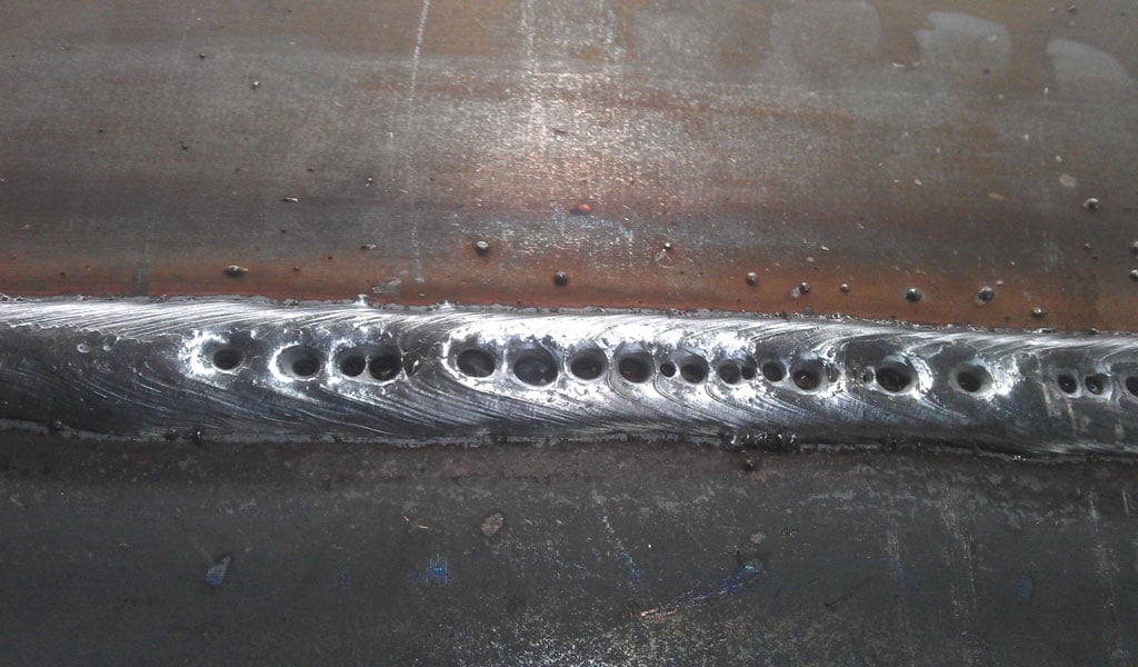
Porosity
Porosity refers to gas pockets or voids trapped within the weld metal during solidification. These voids weaken the weld by reducing its cross-sectional area and creating stress concentrations. Porosity appears as spherical or elongated cavities and is classified into:
- Uniform Porosity: Evenly distributed voids throughout the weld.
- Clustered Porosity: Groups of voids concentrated in specific areas.
- Linear Porosity: Voids aligned along the weld axis, often indicating contamination.
- Surface-Breaking Porosity: Voids that extend to the weld surface, visible during inspection.
Porosity is caused by:
- Contamination of the weld pool by moisture, oil, or grease.
- Inadequate shielding gas coverage, allowing atmospheric gases to enter the weld pool.
- Improper welding parameters, such as excessive arc length or high travel speed.
Slag Inclusions
Slag inclusions are non-metallic residues trapped within the weld metal or between weld passes. Slag is a byproduct of flux-based welding processes like shielded metal arc welding (SMAW) or submerged arc welding (SAW). If not properly removed between passes, slag can become entrapped, creating weak zones in the weld. Slag inclusions are typically irregular in shape and may be elongated or clustered. Common causes include:
- Incomplete slag removal between weld passes.
- Improper electrode angle or manipulation, trapping slag in the weld pool.
- Low heat input, preventing complete melting of the flux.
Incomplete Fusion
Incomplete fusion, also known as lack of fusion (LOF), occurs when the weld metal fails to fully bond with the base metal or between weld passes. This defect appears as unbonded interfaces within the weld and significantly reduces the joint’s strength. Incomplete fusion is caused by:
- Insufficient heat input, preventing complete melting of the base metal.
- Improper electrode angle or manipulation, limiting weld pool penetration.
- Contamination of the weld surfaces, inhibiting bonding.
Incomplete Penetration
Incomplete penetration, or lack of penetration (LOP), occurs when the weld metal does not extend through the full thickness of the joint, leaving an unbonded region at the root. This defect is common in single-sided welds and weakens the joint under tensile or bending loads. Causes include:
- Insufficient welding current or voltage, limiting penetration depth.
- Improper joint preparation, such as inadequate root gap or bevel angle.
- Excessive travel speed, reducing the time available for penetration.
Metallurgical Defects
Metallurgical defects arise from changes in the microstructure or composition of the weld metal or HAZ, often due to improper welding conditions or material incompatibilities. These defects are less visible than surface or subsurface defects but can severely impact the weld’s performance.
Cracks
Cracks are linear discontinuities that represent partial or complete fractures in the weld metal or HAZ. They are among the most critical welding defects due to their potential to propagate and cause failure. Cracks are classified based on their orientation, location, and formation mechanism:
- Longitudinal Cracks: Cracks parallel to the weld axis, often caused by high residual stresses or shrinkage during cooling.
- Transverse Cracks: Cracks perpendicular to the weld axis, typically resulting from hydrogen-induced cracking or excessive transverse stresses.
- Crater Cracks: Star-shaped cracks at the end of a weld bead, caused by improper termination of the arc.
- Root Cracks: Cracks at the weld root, often due to insufficient penetration or contamination.
- Toe Cracks: Cracks at the weld toe, initiated by stress concentrations or undercut.
- Hot Cracks: Cracks that form during solidification, caused by low-melting-point constituents in the weld pool.
- Cold Cracks: Cracks that develop after the weld has cooled, often due to hydrogen embrittlement.
Crack formation is influenced by:
- High cooling rates, leading to brittle microstructures.
- Hydrogen entrapment from moisture, oil, or shielding gas.
- Material properties, such as high carbon content or susceptibility to embrittlement.
Lamellar Tearing
Lamellar tearing is a cracking phenomenon that occurs in the base metal beneath the weld, particularly in thick plates with poor through-thickness ductility. It is caused by tensile stresses acting perpendicular to the plate’s rolling direction, combined with inclusions or laminations in the base metal. Lamellar tearing is common in T-joints or corner joints and can be mitigated by:
- Using materials with improved through-thickness properties.
- Modifying joint designs to reduce stress concentrations.
- Applying buttering layers to redistribute stresses.
Weld Imperfections Due to Heat-Affected Zone (HAZ) Changes
The HAZ undergoes significant microstructural changes due to the thermal cycles of welding, which can lead to defects such as:
- HAZ Hardening: Increased hardness in the HAZ due to rapid cooling, making it susceptible to cracking. This is common in high-carbon or low-alloy steels.
- HAZ Softening: Loss of strength in the HAZ due to prolonged heat exposure, reducing the joint’s load-bearing capacity.
- Grain Growth: Excessive grain coarsening in the HAZ, leading to reduced toughness and ductility.
These changes are influenced by the welding process, heat input, and base metal composition.
Causes of Welding Defects
Welding defects arise from a combination of factors related to the welding process, materials, equipment, and operator skill. Understanding these causes is critical for implementing effective preventive measures. Below is a detailed analysis of the primary causes of welding defects.
Process-Related Causes
The welding process itself can introduce defects if not properly controlled. Common process-related causes include:
- Improper Welding Parameters: Incorrect settings for current, voltage, travel speed, or arc length can lead to defects like porosity, incomplete fusion, or undercut. For example, excessive current may cause burn-through, while insufficient current may result in lack of penetration.
- Inadequate Shielding Gas: In processes like GMAW or GTAW, insufficient or turbulent shielding gas flow allows atmospheric gases (nitrogen, oxygen, or hydrogen) to contaminate the weld pool, causing porosity or inclusions.
- Incorrect Electrode Selection: Using an electrode incompatible with the base metal or welding position can lead to defects like slag inclusions or incomplete fusion. For instance, a high-hydrogen electrode may increase the risk of cold cracking.
- Improper Joint Preparation: Inadequate cleaning, incorrect bevel angles, or insufficient root gaps can prevent proper fusion or penetration, leading to defects like incomplete penetration or slag inclusions.
- Arc Instability: Unstable arcs, caused by fluctuating power supplies or improper electrode manipulation, can result in spatter, porosity, or uneven weld beads.
Material-Related Causes
The properties and condition of the base metal and filler material significantly influence weld quality. Material-related causes include:
- Contamination: Surface contaminants such as oil, grease, rust, or moisture can introduce porosity, inclusions, or cracks. For example, moisture on the base metal can release hydrogen into the weld pool, leading to hydrogen-induced cracking.
- Material Composition: High carbon content, sulfur, or phosphorus in the base metal can increase the risk of hot cracking or embrittlement. Similarly, mismatched filler metals may cause metallurgical incompatibilities.
- Inclusions: Non-metallic inclusions in the base metal, such as oxides or sulfides, can become trapped in the weld, reducing its strength.
- Material Thickness: Thick plates are more prone to defects like lamellar tearing or HAZ cracking due to higher residual stresses and slower cooling rates.
Equipment-Related Causes
Welding equipment must be maintained and operated correctly to avoid defects. Equipment-related causes include:
- Faulty Power Supplies: Inconsistent voltage or current output can lead to arc instability, resulting in defects like spatter or incomplete fusion.
- Worn Consumables: Degraded contact tips, nozzles, or electrodes in GMAW or GTAW can disrupt shielding gas flow or arc stability, causing porosity or uneven welds.
- Improper Gas Delivery Systems: Leaks, blockages, or incorrect gas mixtures in shielding gas systems can introduce contamination, leading to porosity or inclusions.
- Misaligned Equipment: Misalignment of welding torches, fixtures, or workpieces can result in improper weld placement, leading to defects like overlap or incomplete penetration.
Operator-Related Causes
Welder skill and technique play a crucial role in weld quality. Operator-related causes include:
- Poor Technique: Incorrect electrode angles, weaving patterns, or travel speeds can lead to defects like undercut, overlap, or incomplete fusion. For example, holding the electrode too far from the workpiece may cause porosity.
- Inadequate Training: Welders lacking proper training may misinterpret welding procedures or fail to follow specifications, increasing the likelihood of defects.
- Fatigue or Distraction: Human error due to fatigue, distraction, or lack of focus can result in inconsistent welds or arc strikes.
- Improper Weld Termination: Abruptly stopping the arc without filling the crater can cause crater cracks or porosity at the weld’s end.
Environmental Causes
External conditions can also affect weld quality. Environmental causes include:
- High Humidity: Moisture in the air or on the workpiece can introduce hydrogen into the weld pool, leading to porosity or cracking.
- Wind or Drafts: Air currents can disrupt shielding gas coverage in outdoor welding, causing contamination and porosity.
- Temperature Extremes: Cold temperatures can increase cooling rates, leading to HAZ hardening or cracking, while high temperatures may cause excessive heat input and burn-through.
Remedies for Welding Defects
Addressing welding defects requires a combination of preventive measures, inspection techniques, and corrective actions. Remedies vary depending on the defect’s type, severity, and location. Below is a detailed discussion of remedies for common welding defects, organized by defect category.
Remedies for Surface Defects
Surface defects are often easier to detect and repair than subsurface or metallurgical defects. Remedies include:
- Weld Imperfections:
- Excessive Reinforcement: Grind down the excess weld metal to achieve the desired profile, ensuring compliance with standards like AWS D1.1. Adjust welding parameters to prevent recurrence.
- Insufficient Reinforcement: Deposit additional weld metal to build up the bead, ensuring proper fusion. Optimize filler metal delivery and travel speed.
- Overlap: Remove the overlapped material by grinding or gouging, then reweld the area. Train welders to maintain proper electrode angles.
- Spatter: Clean the weld surface using wire brushes or grinding. Adjust shielding gas flow and welding parameters to stabilize the arc.
- Surface Cracks: Grind out the cracked area to remove the defect, then reweld using proper techniques. Preheat the base metal to reduce cooling rates and stresses.
- Undercut:
- Fill the undercut groove with additional weld metal, ensuring proper fusion with the base metal. Adjust welding parameters to reduce current or improve electrode manipulation.
- Use multi-pass welding to minimize undercut in thick joints.
- Train welders to avoid excessive weaving or improper torch angles.
- Arc Strikes:
- Grind or blend the affected area to remove surface damage and restore smoothness.
- Inspect for underlying cracks using magnetic particle testing (MT) or dye penetrant testing (PT).
- Train welders to avoid accidental arc initiation and use proper grounding techniques.
Remedies for Subsurface Defects
Subsurface defects require careful detection and repair, as they are not visible on the weld surface. Remedies include:
- Porosity:
- Remove the affected weld metal by gouging or grinding, then reweld the area using clean materials and proper shielding gas.
- Clean the base metal thoroughly to remove contaminants like oil, grease, or moisture.
- Optimize welding parameters, such as increasing shielding gas flow or reducing arc length, to prevent gas entrapment.
- Use low-hydrogen electrodes or dry flux to minimize hydrogen-induced porosity.
- Slag Inclusions:
- Excavate the inclusion by grinding, gouging, or arc gouging, then reweld the area.
- Ensure thorough slag removal between weld passes using chipping hammers or wire brushes.
- Adjust electrode angles and welding parameters to promote complete melting of the flux.
- Incomplete Fusion:
- Remove the unbonded area by grinding or gouging, then reweld with increased heat input to ensure proper fusion.
- Clean the weld surfaces to remove oxides or contaminants that inhibit bonding.
- Train welders to maintain proper electrode angles and travel speeds.
- Incomplete Penetration:
- Excavate the root area to remove the unpenetrated zone, then reweld with adjusted parameters to achieve full penetration.
- Modify joint preparation to include wider root gaps or appropriate bevel angles.
- Use backing bars or consumable inserts in single-sided welds to support penetration.
Remedies for Metallurgical Defects
Metallurgical defects often require a combination of process adjustments and material treatments to address underlying issues. Remedies include:
- Cracks:
- Hot Cracks: Adjust welding parameters to reduce heat input and control cooling rates. Use filler metals with low sulfur or phosphorus content to minimize segregation.
- Cold Cracks: Preheat the base metal to reduce cooling rates and diffuse hydrogen. Use low-hydrogen electrodes or processes like GTAW to minimize hydrogen entrapment. Post-weld heat treatment (PWHT) can relieve residual stresses and improve toughness.
- Crater Cracks: Train welders to use proper arc termination techniques, such as back-stepping or tapering the weld pool. Fill craters with additional weld metal before stopping.
- Root and Toe Cracks: Grind out the cracked area and reweld with proper techniques. Modify joint designs to reduce stress concentrations, such as adding fillets or chamfers.
- Lamellar Tearing:
- Redesign the joint to minimize through-thickness stresses, such as using butt joints instead of T-joints.
- Use materials with improved Z-direction ductility, certified for low inclusion content.
- Apply buttering layers to the base metal before welding to redistribute stresses.
- Use lower-strength filler metals to reduce shrinkage stresses.
- HAZ Changes:
- HAZ Hardening: Preheat the base metal to slow cooling rates and reduce martensite formation. Use post-weld heat treatment to temper the HAZ and restore ductility.
- HAZ Softening: Adjust welding parameters to minimize heat input and preserve the base metal’s strength. Select filler metals that match or exceed the base metal’s properties.
- Grain Growth: Use multi-pass welding with controlled heat input to refine grain structure. Employ advanced processes like pulsed GMAW to limit HAZ exposure.
Preventive Measures
Preventing welding defects is often more cost-effective than repairing them. Key preventive measures include:
- Welding Procedure Specifications (WPS): Develop and follow WPS documents that outline optimal parameters, joint preparations, and filler materials for each welding process.
- Welder Qualification: Ensure welders are trained and certified to perform specific welds, as per standards like AWS QC1 or ASME Section IX.
- Material Control: Store electrodes, fluxes, and filler metals in dry, controlled environments to prevent contamination. Verify base metal properties before welding.
- Equipment Maintenance: Regularly inspect and calibrate welding machines, gas delivery systems, and consumables to ensure consistent performance.
- Pre-Weld Preparation: Clean base metals thoroughly and verify joint fit-up to ensure proper alignment and penetration.
- Environmental Controls: Use wind shields or enclosures to protect outdoor welds from drafts and maintain stable welding conditions.
- Non-Destructive Testing (NDT): Implement regular NDT, such as RT, UT, or MT, to detect defects early and verify weld quality.
Comparative Tables
To facilitate a clearer understanding of welding defects, their causes, and remedies, the following tables provide detailed comparisons across defect types.
| Defect | Characteristics | Primary Causes | Remedies | Prevention |
|---|---|---|---|---|
| Excessive Reinforcement | Weld bead protrudes excessively above base metal, adding weight and stress risers. | High current, slow travel speed, excessive filler metal. | Grind to desired profile; adjust parameters for rewelding. | Optimize current, travel speed, and filler delivery per WPS. |
| Insufficient Reinforcement | Weld bead too thin, reducing joint strength. | Low filler metal, high travel speed, insufficient heat input. | Deposit additional weld metal; ensure proper fusion. | Verify filler metal and travel speed settings. |
| Overlap | Weld metal extends beyond toe without fusion, creating weak bond. | Incorrect electrode angle, low heat input, improper technique. | Grind out overlap; reweld with correct technique. | Train welders on proper electrode angles and heat input. |
| Spatter | Molten droplets solidify on base metal, causing uneven surface. | Unstable arc, improper shielding gas, high current. | Clean with wire brush or grinding; adjust gas flow and parameters. | Stabilize arc with proper gas flow and current settings. |
| Undercut | Groove at weld toe, reducing base metal thickness. | Excessive current, wide weaving, inadequate shielding gas. | Fill with weld metal; grind if necessary; adjust parameters. | Use controlled weaving and optimized current; ensure gas coverage. |
| Arc Strikes | Localized burns or craters outside weld zone, potential crack initiation sites. | Accidental electrode contact, poor grounding, careless technique. | Grind to remove damage; inspect for cracks with NDT; reweld if needed. | Train welders on grounding and arc control; use anti-spatter devices. |
| Defect | Characteristics | Primary Causes | Remedies | Prevention |
|---|---|---|---|---|
| Porosity | Gas pockets or voids within weld metal, reducing strength. | Contamination (moisture, oil), inadequate shielding gas, improper parameters. | Gouge or grind out; reweld with clean materials and proper gas flow. | Clean base metal; ensure adequate shielding gas; use low-hydrogen consumables. |
| Slag Inclusions | Non-metallic residues trapped in weld, creating weak zones. | Incomplete slag removal, improper electrode angle, low heat input. | Excavate inclusion; reweld with proper technique; ensure slag removal between passes. | Thoroughly clean between passes; optimize electrode angle and heat input. |
| Incomplete Fusion | Unbonded areas between weld and base metal or weld passes, reducing strength. | Low heat input, improper angle, contamination, high travel speed. | Grind out defect; reweld with increased heat and clean surfaces. | Use proper heat input and angle; clean weld surfaces thoroughly. |
| Incomplete Penetration | Weld metal does not extend through joint thickness, leaving unbonded root. | Low current, improper joint prep, excessive travel speed. | Excavate root; reweld with adjusted parameters; modify joint design if needed. | Ensure proper joint prep and parameters; use backing bars if necessary. |
| Defect | Characteristics | Primary Causes | Remedies | Prevention |
|---|---|---|---|---|
| Hot Cracks | Cracks during solidification, often in weld metal center. | High sulfur/phosphorus, rapid cooling, improper filler metal. | Adjust parameters to control cooling; use low-impurity fillers; reweld if needed. | Select compatible fillers; control heat input and cooling rates. |
| Cold Cracks | Cracks after cooling, often in HAZ or weld metal. | Hydrogen entrapment, high stresses, brittle microstructure. | Preheat; use low-hydrogen electrodes; apply PWHT; grind and reweld if needed. | Preheat base metal; use low-hydrogen consumables; apply PWHT. |
| Crater Cracks | Star-shaped cracks at weld end due to improper termination. | Abrupt arc stop, insufficient filler at crater. | Fill crater before stopping; grind out cracks; reweld with proper termination. | Train welders on crater filling and arc termination techniques. |
| Lamellar Tearing | Cracking in base metal beneath weld, parallel to rolling direction. | Through-thickness stresses, inclusions, poor Z-direction ductility. | Redesign joint; use buttering layers; grind and reweld if needed. | Use Z-quality materials; modify joint to reduce stresses; apply buttering. |
| HAZ Hardening | Increased hardness in HAZ, prone to cracking. | Rapid cooling, high-carbon/alloy content, low preheat. | Preheat; apply PWHT to temper HAZ; adjust parameters to slow cooling. | Preheat base metal; control cooling rates; select low-hardenability alloys. |
| HAZ Softening | Loss of strength in HAZ due to excessive heat. | Prolonged heat exposure, high heat input, sensitive alloys. | Adjust parameters to minimize heat; use matching fillers; reweld if needed. | Control heat input; select resistant alloys; use multi-pass welding. |
| Welding Process | Common Defects | Susceptibility Factors | Mitigation Strategies |
|---|---|---|---|
| Shielded Metal Arc Welding (SMAW) | Slag inclusions, porosity, cracks, undercut. | Manual process, electrode coating issues, welder skill dependency. | Use dry electrodes; ensure slag removal; train welders; optimize parameters. |
| Gas Metal Arc Welding (GMAW) | Porosity, spatter, incomplete fusion, undercut. | Shielding gas disruptions, wire feed issues, high automation dependency. | Stabilize gas flow; maintain wire feeder; adjust voltage and current; use anti-spatter. |
| Gas Tungsten Arc Welding (GTAW) | Porosity, incomplete fusion, tungsten inclusions, cracks. | Contamination sensitivity, precise control needed, low deposition rate. | Clean thoroughly; use high-purity gas; maintain tungsten electrode; control heat. |
| Flux-Cored Arc Welding (FCAW) | Slag inclusions, porosity, undercut, incomplete penetration. | Flux quality, shielding gas issues, high deposition rate challenges. | Use quality flux; ensure gas coverage; adjust parameters; clean between passes. |
| Submerged Arc Welding (SAW) | Slag inclusions, incomplete penetration, cracks, porosity. | Flux contamination, joint alignment issues, high heat input risks. | Maintain clean flux; verify joint fit-up; control heat input; use proper electrodes. |
Advanced Techniques for Defect Detection
Detecting welding defects is a critical step in quality assurance. Non-destructive testing (NDT) methods are widely used to identify defects without damaging the weld. Common NDT techniques include:
- Visual Inspection (VT): The simplest and most cost-effective method, used to detect surface defects like undercut, spatter, or surface cracks. Requires trained inspectors and good lighting.
- Radiographic Testing (RT): Uses X-rays or gamma rays to produce images of the weld’s interior, revealing subsurface defects like porosity, inclusions, or incomplete fusion. Ideal for butt welds but limited by cost and safety concerns.
- Ultrasonic Testing (UT): Employs high-frequency sound waves to detect internal defects by analyzing echo patterns. Highly sensitive and versatile but requires skilled operators.
- Magnetic Particle Testing (MT): Detects surface and near-surface cracks in ferromagnetic materials by applying magnetic fields and iron particles. Limited to specific materials.
- Dye Penetrant Testing (PT): Uses a colored dye to reveal surface-breaking defects like cracks or porosity. Simple and effective for non-porous materials.
- Eddy Current Testing (ECT): Detects surface and near-surface defects in conductive materials using electromagnetic fields. Useful for automated inspections.
Each method has its advantages and limitations, and the choice depends on the weld type, material, and inspection requirements. For critical applications, multiple NDT methods may be combined to ensure comprehensive defect detection.
Standards and Codes for Welding Defects
Welding defects are evaluated against industry standards and codes that define acceptable limits for discontinuities. Key standards include:
- AWS D1.1 (Structural Welding Code – Steel): Specifies acceptance criteria for welds in structural steel applications, covering defects like cracks, porosity, and incomplete fusion.
- ASME Section IX (Welding and Brazing Qualifications): Provides guidelines for qualifying welding procedures and welders, including defect evaluation for pressure vessels and piping.
- ISO 5817 (Quality Levels for Imperfections): Defines quality levels (B, C, D) for weld imperfections, with specific tolerances for defects like undercut, porosity, and cracks.
- API 1104 (Welding of Pipelines): Outlines defect acceptance criteria for pipeline welds, emphasizing defects like incomplete penetration and cracks.
These standards ensure that welds meet safety, performance, and reliability requirements, guiding inspectors and engineers in defect assessment.
Case Studies of Welding Defects
To illustrate the practical implications of welding defects, consider the following case studies:
Case Study 1: Pipeline Failure Due to Incomplete Penetration
In 2018, a natural gas pipeline in North America experienced a rupture during pressure testing, causing significant downtime and repair costs. Investigation revealed incomplete penetration at the girth welds, attributed to insufficient welding current and improper joint preparation. The defect reduced the weld’s ability to withstand internal pressure, leading to failure. Corrective actions included:
- Revising the welding procedure to increase current and verify joint fit-up.
- Implementing 100% radiographic testing for girth welds.
- Retraining welders to ensure compliance with API 1104 standards.
This case underscores the importance of proper welding parameters and inspection to prevent critical defects in high-stakes applications.
Case Study 2: Aerospace Component Cracking
An aerospace manufacturer detected transverse cracks in the HAZ of a titanium alloy component during ultrasonic testing. The cracks were caused by hydrogen embrittlement, resulting from inadequate shielding gas coverage during GTAW. Remedies included:
- Grinding out the cracked areas and rewelding with high-purity argon gas.
- Introducing stricter controls for gas delivery systems.
- Applying post-weld heat treatment to diffuse residual hydrogen.
The incident highlighted the need for precise process control in welding sensitive materials like titanium.
Case Study 3: Bridge Weld Imperfections
During the construction of a steel bridge, inspectors identified excessive reinforcement and undercut in several fillet welds, compromising fatigue resistance. The defects were caused by inconsistent welder technique and high welding currents. Corrective measures included:
- Grinding down excess reinforcement and filling undercut areas.
- Standardizing welding parameters across the project.
- Conducting welder refresher training to improve consistency.
This case demonstrates the role of welder skill and parameter control in achieving durable welds for infrastructure projects.
Conclusion
Advancements in welding technology and inspection methods are reshaping how defects are prevented and detected. Emerging trends include:
- Automation and Robotics: Automated welding systems, such as robotic GMAW or laser welding, offer precise control over parameters, reducing defects like incomplete fusion or porosity. These systems use real-time monitoring to adjust welding conditions dynamically.
- Artificial Intelligence (AI): AI-powered inspection tools analyze NDT data to identify defects with higher accuracy and speed than traditional methods. Machine learning models can also predict defect formation based on welding parameters and material properties.
- Advanced Materials: The development of low-defect filler metals and base materials with improved weldability reduces the risk of cracks, inclusions, and HAZ issues.
- In-Process Monitoring: Sensors embedded in welding equipment monitor arc stability, heat input, and shielding gas flow, enabling real-time defect prevention.
- Additive Manufacturing Integration: Hybrid welding-additive manufacturing processes allow for defect-free fabrication of complex components, minimizing traditional welding imperfections.
These innovations promise to enhance weld quality, reduce inspection costs, and improve the reliability of welded structures across industries.
Welding defects represent a significant challenge in achieving high-quality welds, but their impact can be mitigated through careful process control, skilled welding practices, and robust inspection techniques. By understanding the definitions, classifications, causes, and remedies for defects like cracks, porosity, incomplete fusion, and undercut, welders and engineers can ensure the safety and performance of welded assemblies. The comparative tables provided in this article offer a clear reference for diagnosing and addressing defects, while case studies highlight their real-world implications. As welding technology evolves, advancements in automation, AI, and materials science will further reduce the occurrence of defects, paving the way for stronger, more reliable welds in critical applications.
The Detail Of BE-CU Sheet Metal Company
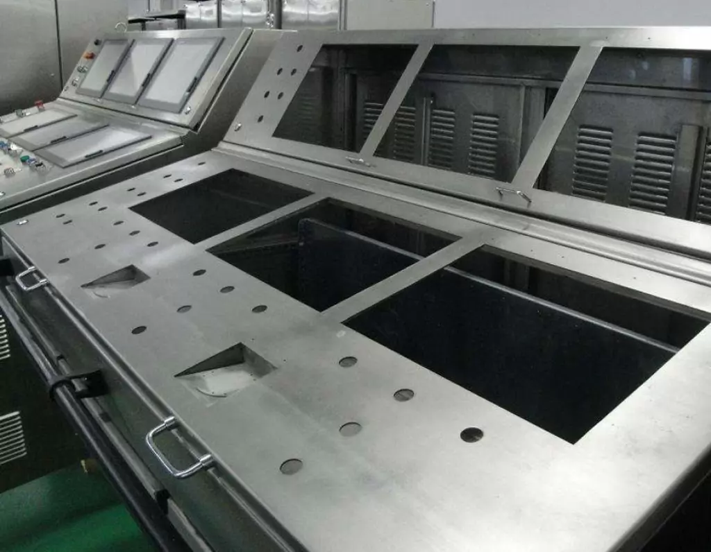
BE-CU is a professional and technical enterprise engaged in sheet metal fabrication, with over 2000 m2 sheet metal workshop and has one-stop service of industrial automation R&D, production, processing and sales.Custom manufacturer of sheet metal component assemblies made from stainless steel, aluminum and carbon steel. Offered in different specifications and features.Markets served include aerospace, lighting, medical, defense, semiconductor/electronics, capacitor, chemical processing and energy.Capable of maintaining dimensional tolerance up to +/-0.005 in. Capabilities include contract manufacturing, fabrication, machining, bending, milling, cutting, forming, drilling, fitting, assembly, notching, punching, rolling, turning, CNC press braking, flame and high definition plasma cutting, saw cutting, shearing, prototyping, high volume, short run and long run production and MIG, TIG and arc welding. Secondary services include Blanchard grinding, galvanizing and painting.
-
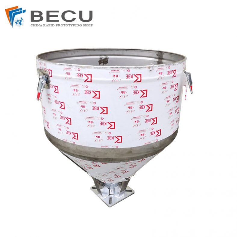
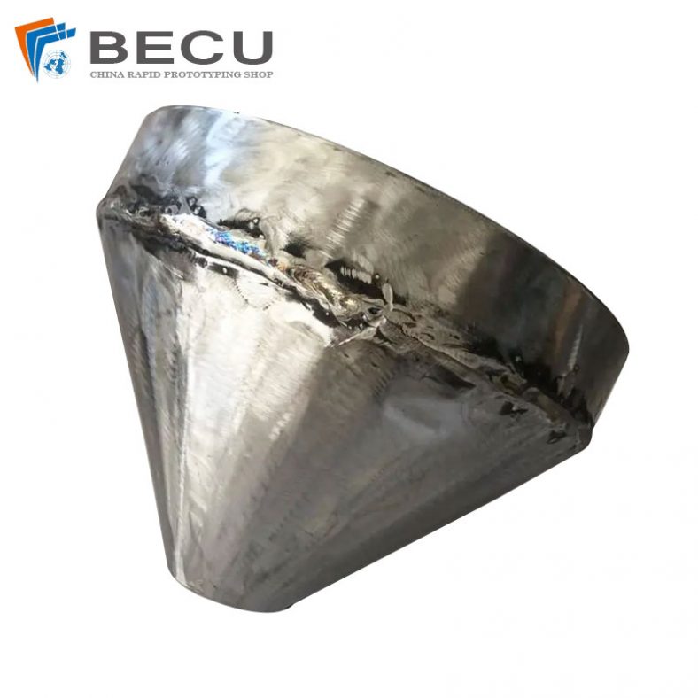
Sheet Metal Fabrication Injection Molding Machine Hopper
-
Sheet Metal Fabrication Funnel For Agricultural Machinery
-
Sheet Metal Fabrication Galvanized Spiral Air Duct
-
PCS Fan Ductwork Sheet Metal Housing
-
Custom Sheet Metal Surgical Instrument Sterilization Box For Beauty Salon
-
Precision Fabrication Green Energy EV Charging Station Cabinet
-
TA1TA2 Alloy Sheet Metal Manufacturing Machinery Support Parts
-
Sheet Metal Fabrication Aluminum 5052 Medical Box For Fire Fighting