

Flow marks, also referred to as flow lines, flow streaks, or weld lines in certain contexts, are surface imperfections that occur during the injection molding process. These visual defects manifest as wavy, streaky, or rippled patterns on the surface of molded plastic parts. They are typically caused by variations in the flow behavior of molten plastic as it fills the mold cavity. While flow marks do not always compromise the structural integrity of the part, they are often considered undesirable in applications where aesthetics are a priority, such as consumer products, automotive components, and medical devices. Understanding the origins of flow marks and implementing strategies to prevent them is critical for manufacturers aiming to achieve high-quality finishes and consistent production outcomes.
Injection molding is a widely used manufacturing process in which molten plastic is injected into a mold cavity under high pressure, cooled, and solidified to form a precise, repeatable shape. The process is highly efficient for producing complex geometries with tight tolerances, making it a cornerstone of modern industrial production. However, the complexity of material flow during injection introduces challenges, one of which is the formation of flow marks. These defects arise due to a combination of material properties, mold design, and processing conditions, all of which interact in intricate ways during the molding cycle.
Flow marks are particularly noticeable on glossy or smooth surfaces, where the human eye can easily detect irregularities in texture or color. They may appear as faint lines, concentric ripples, or irregular streaks, depending on the specific conditions under which they form. In some cases, flow marks are accompanied by slight variations in gloss or color, further accentuating their presence. For industries where surface quality is paramount, such as in the production of electronic housings or decorative trim, flow marks can lead to increased rejection rates, higher costs, and customer dissatisfaction.
To fully grasp the nature of flow marks, it is necessary to explore the physics of polymer flow, the role of mold design, and the influence of processing parameters. This article delves into the science behind flow marks, their causes, and the myriad strategies available to prevent them, offering a comprehensive resource for engineers, designers, and manufacturers seeking to optimize injection molding processes.
The Science Behind Flow Marks
Polymer Flow Dynamics
At the heart of flow marks lies the behavior of molten plastic as it moves through the mold. Polymers used in injection molding, such as polypropylene (PP), acrylonitrile butadiene styrene (ABS), polycarbonate (PC), and polyethylene (PE), are viscoelastic materials. This means they exhibit both viscous and elastic properties when subjected to shear forces during injection. As the molten polymer is forced through the mold’s gates and runners into the cavity, it encounters varying levels of resistance, temperature gradients, and shear stresses, all of which influence its flow pattern.
Flow marks typically form when the advancing flow front of the polymer cools prematurely or experiences inconsistent flow rates. The flow front is the leading edge of the molten plastic as it fills the mold cavity. When this front moves too slowly or encounters obstacles—such as thin walls, sharp corners, or changes in mold geometry—it may begin to solidify before fully integrating with subsequent material. This partial solidification creates visible boundaries or lines on the surface, which are perceived as flow marks.
The viscosity of the polymer plays a critical role in this process. Viscosity, a measure of a fluid’s resistance to flow, is highly temperature-dependent in thermoplastics. At higher temperatures, the polymer is less viscous and flows more easily, while at lower temperatures, it becomes thicker and more resistant to movement. If the mold or melt temperature is insufficient, the polymer may not maintain uniform flow, leading to the formation of flow marks. Additionally, shear thinning—a phenomenon where viscosity decreases under high shear rates—can complicate flow behavior, particularly in narrow sections of the mold.
Cooling and Solidification Effects
Cooling is another key factor in the development of flow marks. Injection molds are typically equipped with cooling channels that circulate water or another coolant to extract heat from the molten plastic, allowing it to solidify into its final shape. However, if the cooling rate is uneven across the mold—due to poor channel design or inadequate coolant flow—the polymer may solidify at different rates in different areas. This differential cooling can cause the flow front to hesitate or stall, resulting in visible surface defects.
For example, when the flow front contacts a cold mold wall, it may form a thin solidified layer, while the hotter material behind it continues to flow. This creates a ripple effect as the two layers interact, leaving behind a flow mark. The thickness of this initial layer, known as the “frozen layer,” depends on the thermal conductivity of the polymer, the mold material (typically steel or aluminum), and the temperature differential between the melt and the mold.
Mold Geometry and Flow Path
The design of the mold itself significantly influences the likelihood of flow marks. Complex geometries, such as thin walls, sharp transitions, or intricate features, can disrupt the smooth flow of molten plastic. For instance, a mold with a narrow gate may cause the polymer to jet into the cavity rather than flow uniformly, leading to turbulence and surface imperfections. Similarly, abrupt changes in wall thickness can create areas of high shear or stagnation, both of which contribute to flow mark formation.
The location and size of the gate—the entry point where molten plastic enters the cavity—are particularly critical. A gate that is too small may restrict flow, causing the polymer to cool prematurely, while a gate positioned improperly may lead to uneven filling patterns. Multi-gate molds, used for larger parts, can also introduce flow marks if the flow fronts from different gates meet imperfectly, forming weld lines that resemble flow marks.
Causes of Flow Marks in Injection Molding
Flow marks are the result of a complex interplay of factors, which can be broadly categorized into material properties, mold design, and processing conditions. Below, each category is explored in detail to provide a thorough understanding of the root causes.
Material Properties
The choice of polymer and its inherent characteristics heavily influence the propensity for flow marks. Highly viscous materials, such as polycarbonate or polyamide (nylon), are more prone to flow marks because they resist flow and solidify quickly upon cooling. Conversely, low-viscosity materials like polyethylene flow more easily but may still exhibit flow marks if processing conditions are suboptimal.
Additives and fillers, such as glass fibers, talc, or pigments, can also affect flow behavior. For example, glass-filled polymers tend to have higher viscosity and reduced flowability, increasing the risk of surface defects. Pigments, particularly metallic or pearlescent ones, can amplify the visibility of flow marks by creating color variations along the flow lines. The melt flow index (MFI), a measure of a polymer’s flowability, is a useful indicator of how a material will behave during injection molding. Materials with a low MFI (indicating higher viscosity) are more challenging to process without defects.
Mold Design Factors
As previously mentioned, mold geometry plays a pivotal role in flow mark formation. Specific design elements that contribute to flow marks include:
- Gate Size and Placement: Small gates increase injection pressure and shear rates, potentially causing jetting and flow marks. Gates placed far from critical surfaces may lead to long flow paths, increasing the chance of premature cooling.
- Wall Thickness Variations: Uneven wall thicknesses create differences in flow resistance and cooling rates, leading to inconsistent flow fronts.
- Surface Texture: Highly polished mold surfaces can highlight flow marks, whereas textured surfaces may mask them, though texture alone does not eliminate the underlying issue.
- Venting: Inadequate venting traps air or gases in the mold, forcing the polymer to flow around these pockets and creating visible marks.
Processing Conditions
The parameters set during the injection molding process—such as temperature, pressure, and injection speed—directly impact flow mark formation. Common processing-related causes include:
- Low Melt Temperature: If the polymer is not heated sufficiently, its viscosity increases, impeding smooth flow and causing flow marks.
- Low Mold Temperature: A cold mold accelerates cooling at the flow front, leading to premature solidification and surface defects.
- Insufficient Injection Pressure: Low pressure may prevent the polymer from filling the mold completely or uniformly, resulting in hesitations that manifest as flow marks.
- Slow Injection Speed: A slow injection rate allows the flow front to cool before the cavity is fully filled, creating visible lines or ripples.
How to Prevent Flow Marks in Injection Molding
Preventing flow marks requires a multifaceted approach that addresses material selection, mold design, and processing optimization. Below are detailed strategies, supported by scientific principles and practical considerations, to minimize or eliminate these defects.
Material Selection and Preparation
Choosing the right polymer is the first step in preventing flow marks. Materials with higher melt flow indices (e.g., high-MFI polypropylene) flow more easily and are less likely to exhibit flow marks, provided other conditions are optimized. For applications requiring high-viscosity materials, such as engineering plastics, preheating the resin to remove moisture and improve flowability can be beneficial. Drying is especially important for hygroscopic polymers like nylon or PET, as moisture content can increase viscosity and exacerbate defects.
When additives are necessary, selecting those that enhance flow—such as plasticizers or lubricants—can reduce the risk of flow marks. Conversely, minimizing the use of fillers that increase viscosity or cause flow irregularities is advisable unless structurally required.
Mold Design Optimization
Effective mold design is crucial for ensuring uniform flow and minimizing defects. Key considerations include:
- Gate Optimization: Increase gate size to reduce shear rates and improve flow. Position gates closer to thick sections or critical surfaces to shorten flow paths and ensure even filling.
- Uniform Wall Thickness: Design parts with consistent wall thicknesses to avoid flow disruptions. Where transitions are unavoidable, use gradual tapers rather than sharp changes.
- Cooling System Design: Incorporate well-distributed cooling channels to maintain a uniform mold temperature. Computational fluid dynamics (CFD) simulations can help optimize channel placement and coolant flow.
- Venting Improvements: Add vents or increase vent depth to release trapped gases, allowing the polymer to fill the cavity smoothly.
- Surface Finish: For aesthetic parts, experiment with mold surface textures to mask flow marks without compromising design intent.
Processing Parameter Adjustments
Fine-tuning processing conditions is often the most immediate and cost-effective way to address flow marks. Recommended adjustments include:
- Increase Melt Temperature: Raise the barrel temperature within the polymer’s recommended range to reduce viscosity and improve flow. For example, ABS typically requires a melt temperature of 220–260°C, while polycarbonate may need 280–320°C.
- Raise Mold Temperature: Increase mold temperature to delay solidification of the flow front. For instance, a mold temperature of 60–80°C for ABS can significantly reduce flow marks compared to 20–40°C.
- Boost Injection Pressure: Higher pressure ensures the cavity fills quickly and uniformly, overcoming resistance that might cause hesitations.
- Adjust Injection Speed: Increase injection speed to maintain a consistent flow front, but avoid excessive speeds that could induce jetting. A balanced speed profile (e.g., starting slow and ramping up) may be ideal for complex parts.
Advanced Techniques
For persistent flow mark issues, advanced techniques can provide additional solutions:
- Hot Runner Systems: These maintain the polymer at a consistent temperature from the barrel to the cavity, reducing cooling-related defects.
- Gas-Assisted Injection Molding: Injecting gas to push the polymer against mold walls can improve surface finish and reduce flow marks in thick parts.
- Simulation Software: Tools like Moldflow or SolidWorks Plastics allow engineers to predict flow behavior and optimize mold design and processing parameters before production begins.
Comparative Analysis of Prevention Methods
To aid manufacturers in selecting the most appropriate prevention strategy, the following tables compare key methods based on effectiveness, cost, and implementation complexity.
| Method | Effectiveness | Cost | Complexity | Notes |
|---|---|---|---|---|
| High-MFI Polymer | High | Low–Moderate | Low | Best for non-structural parts; may compromise strength in some cases. |
| Preheating/Drying | Moderate | Low | Low | Essential for hygroscopic materials; minimal impact on dry resins. |
| Flow-Enhancing Additives | Moderate–High | Moderate | Moderate | Requires testing to avoid altering mechanical properties. |
| Method | Effectiveness | Cost | Complexity | Notes |
|---|---|---|---|---|
| Larger Gate Size | High | Moderate | Moderate | May require mold rework; improves fill but can affect cycle time. |
| Uniform Wall Thickness | High | High | High | Requires part redesign; long-term benefits outweigh initial costs. |
| Enhanced Cooling System | Moderate–High | High | High | Significant upfront investment; ideal for high-volume production. |
| Improved Venting | Moderate | Low–Moderate | Low | Quick fix for gas-related flow marks; less effective for other causes. |
| Method | Effectiveness | Cost | Complexity | Notes |
|---|---|---|---|---|
| Higher Melt Temperature | High | Low | Low | Risk of degradation if exceeds polymer limits; monitor residence time. |
| Higher Mold Temperature | High | Low–Moderate | Low | Increases cycle time slightly; energy costs may rise. |
| Increased Injection Pressure | Moderate–High | Low | Low | Limited by machine capacity; excessive pressure may damage mold. |
| Faster Injection Speed | Moderate | Low | Moderate | Requires fine-tuning to avoid jetting or overpacking. |
Case Studies and Practical Examples
To illustrate the application of these prevention strategies, consider the following hypothetical scenarios:
A manufacturer producing ABS dashboard panels notices flow marks near the gate. Initial settings include a melt temperature of 230°C, mold temperature of 40°C, and a small gate size. After analysis, they increase the melt temperature to 250°C, raise the mold temperature to 70°C, and enlarge the gate by 20%. The result is a 90% reduction in flow marks, with minimal impact on cycle time.
A polycarbonate housing exhibits flow marks due to a thin wall section (1 mm). Redesigning the part to a uniform 2 mm thickness is impractical due to weight constraints. Instead, the team opts for a hot runner system and increases injection speed by 30%. Flow marks are eliminated, though production costs rise by 15% due to the new system.
Conclusion
Flow marks in injection molding are a common challenge that stems from the intricate interplay of polymer flow dynamics, mold design, and processing conditions. By understanding the underlying causes—such as premature cooling, uneven flow fronts, and inadequate mold features—manufacturers can implement targeted strategies to prevent these defects. Material selection, mold optimization, and process adjustments offer a spectrum of solutions, each with its own trade-offs in terms of cost, complexity, and effectiveness.
For high-quality production, a combination of approaches is often necessary, tailored to the specific part geometry, material, and application requirements. Advances in simulation technology and molding techniques continue to enhance the ability to predict and mitigate flow marks, ensuring that injection molding remains a reliable and versatile manufacturing process. Through careful planning and execution, flow marks can be minimized, delivering parts that meet both functional and aesthetic standards.
The Detail Of BE-CU Plastic Injection Company
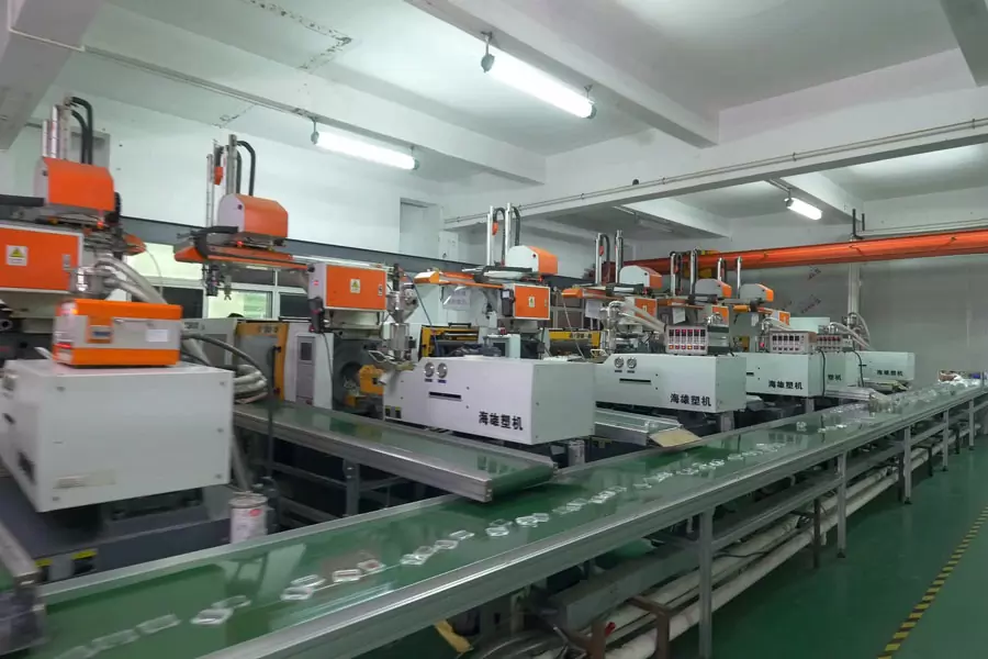
The core cooperative injection molding supplier has twelve 50T-200T injection molding machines, all of which are equipped with manipulators, mold temperature controllers, automatic assembly lines, and dust-free purification workshops. There are 4 automatic production lines in the oil spraying department: one 10,000-level automatic spraying production line (two sprays and two baking), 1 production line (one spray and one baking); 1 manual spraying production line, with a daily output of 150,000 pieces above. With brand-new professional technology, with an environmentally friendly anti-static, fully air-conditioned, dust-free workshop, the working environment is superior, the production equipment is complete, and the product testing equipment is perfect. Need mold making supplies for large quantities of production parts? Looking for a more cost effective and time efficient way of manufacturing parts? Don’t miss our injection molding services! At be-cu.com, we provide high quality and affordable injection molding for prototypes and production parts with quick turnaround times.
-

5 Axis CNC Machining Spiral Bevel Gear Mold
-
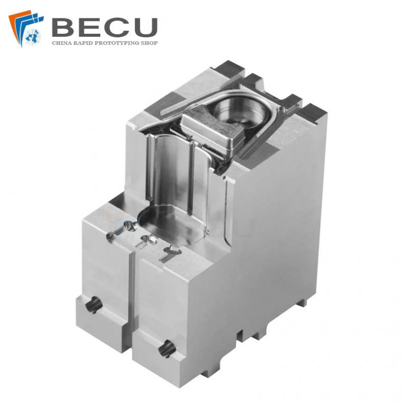
Small Precision Injection Molding Inserts
-
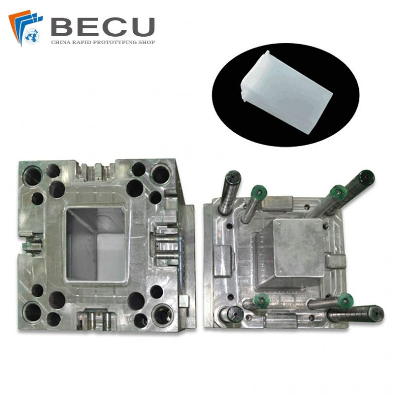
Plastic Storage Box Plastic Injection Mold
-
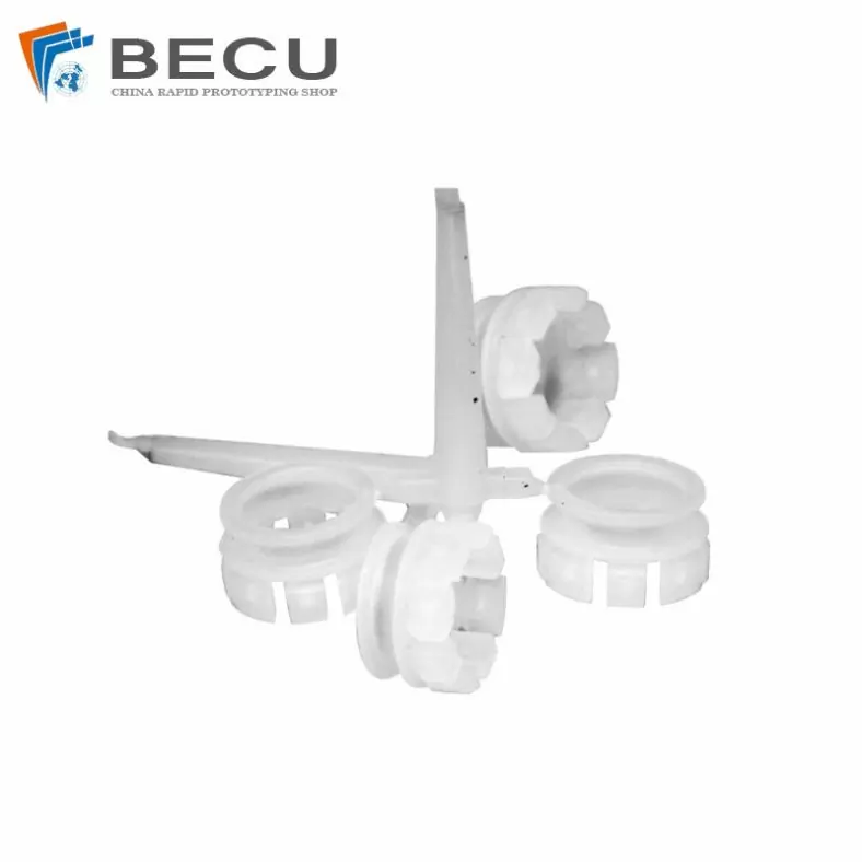
Injection Molding PE-UHMW Retaining Buckle And Ring
-
Cnc Machined UHMW-PE Bottle Turner
-
Shower Inclosure Sleeve By Plastic Injection
-
Injection Secret Security Machine Control Shell
-
Sewing Machine Industrial Control Shell By Plastic Injection