
A spotface hole is a machined feature widely utilized in engineering and manufacturing to create a smooth, flat, and accurately located surface on a workpiece, typically surrounding a pre-existing hole. This feature ensures that components such as fasteners, washers, or mating parts can sit flush against a surface that might otherwise be rough, uneven, or curved due to processes like casting or forging. In contrast, a counterbore hole is a deeper, cylindrical, flat-bottomed recess designed to accommodate the head of a fastener, allowing it to sit flush with or below the workpiece surface. Both spotface and counterbore holes are integral to precision machining, yet they serve distinct purposes, differ in their geometry, and are represented differently in technical drawings.
This article provides a comprehensive exploration of the spotface hole—its definition, symbol, dimensions, and machining processes—while offering an in-depth comparison with counterbore holes to elucidate their differences and applications in modern engineering.
BE-CU.COM
The term “spotface” derives from the combination of “spot,” referring to a specific localized area, and “face,” indicating the process of facing or smoothing that area. Spotfacing, as a machining operation, involves removing a minimal amount of material from the surface of a workpiece to produce a planar region, often concentric with a drilled or cast hole. This operation is particularly relevant in industries such as aerospace, automotive, and heavy machinery, where precision and reliability are paramount. The primary purpose of a spotface is to provide a stable and uniform seating surface for fasteners like bolts, screws, or nuts, ensuring proper load distribution and alignment. By contrast, a counterbore serves a similar yet distinct role: it recesses the fastener head into the material, concealing it either partially or fully below the surface to achieve a flush or streamlined finish.
In mechanical engineering, the distinction between spotface and counterbore holes is critical, as their applications dictate specific design and machining considerations. A spotface is typically shallow—often only a few millimeters or less in depth—while a counterbore is deeper, with its depth determined by the height of the fastener head it is intended to accommodate. This fundamental difference in depth reflects their respective functions: spotfaces prioritize surface quality and flatness, while counterbores emphasize concealment and structural integration of fasteners. Understanding these features requires an examination of their definitions, symbolic representations in engineering drawings, dimensional specifications, machining techniques, and practical applications, all of which will be explored in detail throughout this article.
Definition of a Spotface Hole
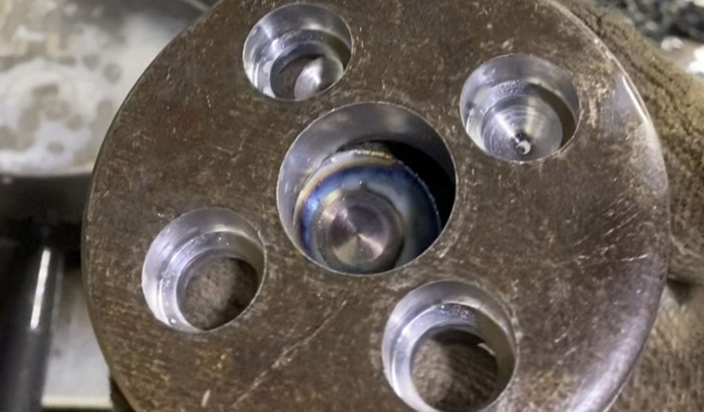
A spotface hole can be defined as a shallow, cylindrical, flat-bottomed recess machined into a workpiece, concentric with an existing hole, such as a drilled or tapped hole. The spotface feature is created by removing just enough material to produce a smooth, flat surface that contrasts with the surrounding material, which may exhibit roughness or irregularity due to manufacturing processes like casting, forging, or stamping. The depth of a spotface is minimal, typically ranging from 0.1 mm to 1 mm, though this can vary depending on the workpiece material, the fastener size, and the specific application requirements.
The diameter of the spotface is generally larger than that of the underlying hole, sized to accommodate the head of a fastener or the contacting surface of a mating component, such as a washer or bearing race.Spotfacing is often considered a secondary machining operation, performed after the primary hole has been drilled or otherwise formed. This process ensures that the seating surface meets stringent tolerances for flatness and perpendicularity relative to the hole’s axis. In engineering terms, a spotface enhances the functionality of a hole by providing a precise landing area, mitigating issues such as uneven stress distribution, misalignment, or poor sealing that could arise from an uneven or rough surface. For example, in a cast iron component with a naturally textured surface, a spotface ensures that a bolt head can sit securely without wobbling or causing localized stress concentrations.
The spotface differs from other machined features, such as counterbores and countersinks, in its shallow nature and its focus on surface preparation rather than recessing. While it shares some geometric similarities with a counterbore—both are cylindrical and flat-bottomed—the spotface’s limited depth sets it apart. This shallow characteristic is intentional, as the spotface is not designed to hide the fastener head but rather to optimize its contact with the workpiece. In technical literature, spotfacing is sometimes described as “facing a spot,” emphasizing its role in localized surface refinement.
Definition of a Counterbore Hole
A counterbore hole, by contrast, is a cylindrical, flat-bottomed recess machined coaxially with a smaller-diameter hole, typically a pilot hole, to create a stepped profile. The counterbore’s larger diameter and greater depth allow it to fully encompass the head of a fastener, such as a socket head cap screw, enabling the fastener to sit flush with or below the surface of the workpiece. The term “counterbore” refers both to the machined feature and the tool used to create it, though the latter is sometimes called a counterbore cutter to avoid ambiguity. In engineering drawings, the counterbore is denoted by the symbol ⌴, a Unicode character (U+2334) that visually represents its stepped geometry.
The counterbore’s primary function is to provide a recessed mounting surface for fasteners, ensuring a clean, unobtrusive finish. This is particularly valuable in applications where protruding fastener heads could interfere with mating parts, pose safety hazards, or detract from aesthetic requirements. For instance, in an automotive engine block, counterbored holes might be used to secure a cylinder head with bolts that must not protrude beyond the surface. The depth of a counterbore is typically equal to or slightly greater than the height of the fastener head, ranging from a few millimeters to over 10 mm, depending on the fastener size and any additional components like washers.
Unlike a spotface, which focuses on surface flatness, a counterbore integrates the fastener into the workpiece, often requiring precise dimensional control to ensure a snug fit. The pilot hole beneath the counterbore—usually a through hole or a tapped hole—serves as the anchor point for the fastener’s threaded shaft, while the counterbore accommodates the head. This dual-hole structure distinguishes the counterbore from other features like countersinks, which have a conical rather than cylindrical profile.
Symbol Representation in Engineering Drawings
In technical drawings, standardized symbols are used to communicate the specifications of spotface and counterbore holes to machinists and engineers. These symbols, governed by standards such as ASME Y14.5 (Geometric Dimensioning and Tolerancing), ensure clarity and consistency across industries. The spotface does not have a unique symbol of its own; instead, it is represented by the counterbore symbol (⌴) with the letters “SF” superimposed inside it. This convention, outlined in ASME Y14.5-2009, indicates that the feature is a shallow variant of a counterbore, designed for surface preparation rather than deep recessing.
The counterbore symbol (⌴), on the other hand, stands alone to denote a deeper, recessed feature. Accompanying the symbol are numerical values specifying the counterbore’s diameter and depth, often followed by the diameter of the pilot hole. For example, a counterbore callout might read “⌴ Ø20 x 5 Ø10,” indicating a 20 mm diameter counterbore with a 5 mm depth above a 10 mm diameter pilot hole. This format ensures that all critical dimensions are conveyed succinctly. In some older drawings or informal contexts, the term “SF” or “SFACE” might be used without the symbol, but modern practice favors the standardized notation.
The use of these symbols is crucial for avoiding misinterpretation during manufacturing. A machinist encountering a spotface callout (⌴ SF) understands that only a shallow cut is required, whereas a counterbore callout (⌴) signals the need for a deeper, more substantial recess. The inclusion of dimensional tolerances—such as ±0.1 mm for diameter or depth—further refines the specification, ensuring the feature meets the designer’s intent.
Dimensions of Spotface and Counterbore Holes
The dimensions of spotface and counterbore holes are tailored to their respective functions, reflecting the geometric and functional requirements of the components they support. For a spotface, the key dimensions are its diameter and depth, though the depth is often less critical and may not always be explicitly specified. The diameter is determined by the size of the fastener head or mating surface it must accommodate, typically ranging from 1.5 to 3 times the diameter of the underlying hole. For instance, a 5.5 mm through hole might have a 12 mm diameter spotface to provide ample seating for a bolt head or washer. The depth, when specified, is usually minimal—on the order of 0.1 mm to 1 mm—just enough to achieve a flat, smooth surface.
In engineering drawings, a spotface dimension might be written as “⌴ SF Ø12 x 0.75,” indicating a 12 mm diameter spotface with a 0.75 mm depth. If no depth is specified, the machinist is expected to remove material until the full diameter is flat, a process often described as “cleaning up” the surface. Tolerances for spotface dimensions are typically tight for diameter (e.g., ±0.25 mm) to ensure proper fit, while depth tolerances may be looser unless the application demands precision.
Counterbore dimensions, by contrast, include the diameter and depth of the counterbore itself, as well as the diameter of the pilot hole. The counterbore diameter is sized to accommodate the fastener head with some clearance—often 2 to 4 times the pilot hole diameter—while the depth is set to match or slightly exceed the head height. For example, a counterbore for an M10 socket head cap screw might be specified as “⌴ Ø20 x 8 Ø10,” where the counterbore is 20 mm in diameter and 8 mm deep, above a 10 mm pilot hole. The pilot hole diameter is determined by the fastener’s thread size, ensuring a secure fit when tapped or cleared.
Tolerances for counterbores are critical, as the fastener must fit snugly without excessive play. A typical tolerance might be ±0.1 mm for the counterbore diameter and ±0.05 mm for the depth, reflecting the need for precision in recessed applications. The stepped profile of a counterbore—transitioning from the larger counterbore to the smaller pilot hole—requires careful machining to maintain concentricity and perpendicularity, often verified using coordinate measuring machines (CMMs) or other metrology tools.
Machining Processes for Spotface Holes
The machining of a spotface hole typically involves a secondary operation following the creation of the primary hole, such as drilling or boring. The process begins with the workpiece secured in a milling machine, drill press, or CNC machine, depending on the precision and volume required. A spotfacing tool—often a counterbore cutter or end mill—is then used to remove material from the surface surrounding the hole. The tool is aligned coaxially with the hole, guided by a pilot (a reduced-diameter section) that fits into the existing hole to ensure concentricity.
In manual machining, a counterbore cutter with a perpendicular cutting face is preferred, as it produces a flat surface with a single plunging cut along the Z-axis. The pilot ensures accurate positioning, while the cutting lips remove just enough material to achieve the desired flatness. In CNC machining, an end mill may be used instead, tracing a circular toolpath in the XY plane to create the spotface. This method allows for greater flexibility in diameter and depth control, though it requires precise programming to avoid convexity from the tool’s relief angle. Zero-angle end mills, designed specifically for spotfacing, can mitigate this issue by mimicking the flat-cutting action of a counterbore cutter.
The depth of material removal in spotfacing is minimal, often requiring only a few passes of the tool. The machinist monitors the process to ensure that the full spotface diameter is achieved without exceeding the specified depth, if provided. Surface finish is a key consideration, with spotfaces typically requiring a smooth texture (e.g., Ra 0.8 µm or better) to optimize fastener seating and load distribution. After machining, the spotface may be deburred to remove any sharp edges or burrs, enhancing safety and fit.
Machining Processes for Counterbore Holes
Counterboring follows a similar workflow but involves deeper material removal and stricter dimensional control. The process begins with drilling the pilot hole—either a through hole or a blind hole—using a standard twist drill or boring tool. The counterbore tool, typically a counterbore cutter with a pilot, is then introduced to enlarge the upper portion of the hole. The pilot fits into the pilot hole, ensuring alignment, while the cutting edges excavate the counterbore to the specified diameter and depth.
In CNC machining, a counterboring end mill may be used, with the tool plunging into the workpiece in stages to achieve the required depth. The stepped profile of the counterbore demands precise control of the Z-axis feed rate to avoid chatter or tool deflection, which could compromise concentricity. For high-volume production, multi-flute counterbore tools or indexable cutters may be employed to improve efficiency and surface quality. The counterbore’s side walls are typically left with a coarser finish (e.g., Ra 1.6 µm) than the bottom, as the fastener head contacts only the flat surface.
Post-machining inspection is critical for counterbores, as the fastener must fit seamlessly within the recess. Depth gauges, calipers, or CMMs are used to verify dimensions, while visual inspection ensures the absence of burrs or irregularities. In some cases, the pilot hole is tapped after counterboring to create threads, requiring additional care to maintain alignment between the threaded portion and the counterbore.
Spotface vs. Counterbore: A Detailed Comparison
The differences between spotface and counterbore holes are rooted in their design intent, geometry, and application. While both features are cylindrical, flat-bottomed recesses machined coaxially with a smaller hole, their depth, function, and symbolic representation distinguish them. Below is an exhaustive comparison, supplemented by detailed tables for clarity.
Functional Purpose
The spotface’s primary function is to provide a smooth, flat seating surface for a fastener or mating component without necessarily recessing it below the surface. This makes it ideal for applications where surface quality is critical, such as ensuring a tight seal with a washer or preventing fastener wobble on an uneven casting. The counterbore, conversely, is designed to fully recess the fastener head, hiding it within the workpiece to achieve a flush or submerged finish. This is essential in assemblies where protruding heads could interfere with other components or where aesthetics demand a streamlined surface.
Depth Specifications
Depth is the most pronounced difference between the two features. A spotface is shallow, typically ranging from 0.1 mm to 1 mm, sufficient only to flatten the surface. Its depth is often unspecified, with the machinist removing material until the full diameter is smooth. A counterbore, however, is deeper—commonly 3 mm to 10 mm or more—matched to the height of the fastener head plus any washers or tolerances. This greater depth allows the counterbore to conceal the fastener, a capability the spotface lacks.
Shape and Geometry
Both spotface and counterbore holes are cylindrical with flat bottoms, but their profiles differ due to depth. A spotface has a simple, shallow cylindrical form, with its bottom perpendicular to the hole axis. A counterbore features a stepped profile, transitioning from the larger-diameter recess to the smaller pilot hole. This stepped geometry is more complex, requiring precise machining to maintain concentricity and ensure the fastener fits correctly.
Callout Symbols
In engineering drawings, the spotface is denoted by the counterbore symbol (⌴) with “SF” inside, reflecting its status as a shallow variant. The counterbore uses the standalone ⌴ symbol, accompanied by dimensions for diameter and depth. These symbols, standardized by ASME Y14.5, ensure that machinists can quickly identify the intended feature and its specifications.
Surface Finish
Surface finish requirements differ based on function. Spotfaces typically demand a finer finish (e.g., Ra 0.4 µm to 0.8 µm) across the entire surface, as their purpose is to optimize contact and load distribution. Counterbores prioritize a smooth bottom (e.g., Ra 0.8 µm) but may tolerate rougher side walls (e.g., Ra 1.6 µm), as the fastener head rests only on the base. This distinction reflects the spotface’s emphasis on surface quality versus the counterbore’s focus on recessing.
Applications
Spotfaces are widely used in scenarios requiring a flat mounting surface on rough or curved workpieces, such as castings, forgings, or 3D-printed parts. They are common in aerospace assemblies, where precision sealing is needed, or in machinery where alignment is critical. Counterbores, by contrast, are employed in applications demanding a flush or recessed fastener, such as automotive panels, electronic enclosures, or structural joints where clearance is limited.
Comparative Tables
To crystallize these differences, the following tables provide a side-by-side comparison of spotface and counterbore holes across multiple parameters.
Table 1: General Characteristics
| Parameter | Spotface Hole | Counterbore Hole |
|---|---|---|
| Definition | Shallow, flat-bottomed recess for seating | Deeper, flat-bottomed recess for recessing |
| Purpose | Provide a smooth, flat surface | Recess fastener head below surface |
| Depth Range | 0.1 mm to 1 mm (typical) | 3 mm to 10 mm+ (typical) |
| Shape | Shallow cylinder | Stepped cylinder |
| Symbol | ⌴ with “SF” inside | ⌴ |
Table 2: Dimensional Specifications
| Dimension | Spotface Hole | Counterbore Hole |
|---|---|---|
| Diameter | 1.5–3x pilot hole diameter | 2–4x pilot hole diameter |
| Depth | Minimal, often unspecified | Matches fastener head height |
| Pilot Hole | Matches fastener shaft | Matches fastener shaft |
| Tolerance (Dia.) | ±0.1 mm to ±0.25 mm | ±0.05 mm to ±0.1 mm |
| Tolerance (Depth) | ±0.25 mm (if specified) | ±0.05 mm |
Table 3: Machining Considerations
| Aspect | Spotface Hole | Counterbore Hole |
|---|---|---|
| Tool | Counterbore cutter, end mill | Counterbore cutter, end mill |
| Process | Shallow plunge or circular interpolation | Deeper plunge or staged cutting |
| Surface Finish | Ra 0.4–0.8 µm (bottom) | Ra 0.8 µm (bottom), Ra 1.6 µm (sides) |
| Machining Time | Faster (less material removed) | Slower (more material removed) |
| Inspection | Flatness, diameter | Depth, concentricity, fit |
Table 4: Applications and Examples
| Application | Spotface Hole | Counterbore Hole |
|---|---|---|
| Industry | Aerospace, machinery | Automotive, electronics |
| Example | Bolt seating on a casting | Socket head screw in a panel |
| Finish Requirement | High (sealing, alignment) | Moderate (recessing, fit) |
| Fastener Type | Bolts, nuts, washers | Socket head cap screws, bolts |
| Surface Condition | Rough, uneven (cast/forged) | Smooth or variable |
Practical Implications in Engineering Design
The choice between a spotface and a counterbore depends on the specific requirements of the design and the intended application. In scenarios where a workpiece has an irregular surface—such as a casting with porosity or a forging with scale—a spotface is the preferred solution to ensure a reliable fastener connection. For example, in the assembly of a turbine housing, spotfaced holes around bolt locations guarantee that the flange mates securely with its counterpart, preventing leaks or misalignment under high pressure.
Conversely, counterbores are selected when the fastener head must be concealed, either for functional clearance or aesthetic reasons. In the design of a consumer electronics enclosure, counterbored holes allow screws to sit below the surface, maintaining a sleek appearance while protecting the fastener from external damage. This choice also facilitates stacking or mating with other components without interference from protruding heads.
The machining process itself influences the decision. Spotfacing is generally faster and less resource-intensive due to its shallow depth, making it cost-effective for large-scale production of parts requiring only surface refinement. Counterboring, with its deeper cut, requires more tool wear and machining time, but its ability to recess fasteners justifies the investment in applications where flushness is non-negotiable.
Advanced Considerations in Spotface and Counterbore Design
Beyond basic functionality, advanced engineering applications introduce additional considerations for spotface and counterbore holes. In high-precision assemblies, such as those in aerospace or medical devices, the tolerances for both features may be tightened to ±0.01 mm or less, necessitating the use of CNC machines with high-resolution controls and metrology-grade inspection. Surface finish requirements may also escalate, with spotfaces achieving Ra 0.2 µm or better to meet stringent sealing standards, such as those for hydraulic systems.
Material properties further complicate the design. In soft materials like aluminum, spotfacing and counterboring are straightforward, but in harder alloys like titanium or stainless steel, tool selection and cutting parameters must be optimized to prevent work hardening or excessive heat buildup. For composite materials, such as carbon fiber-reinforced polymers, special tools with diamond coatings may be required to avoid delamination or fiber pullout during machining.
In some cases, hybrid approaches emerge. For instance, a spotface might be combined with a counterbore in a single feature—known as a “spotfaced counterbore”—to provide both a flat seating surface and a recessed fastener head. This requires a custom callout, such as “⌴ SF Ø20 x 0.5 / Ø15 x 5 Ø10,” indicating a 20 mm spotface to 0.5 mm depth followed by a 15 mm counterbore to 5 mm depth above a 10 mm pilot hole. Such configurations are rare but illustrate the flexibility of these features in complex designs.
Historical Context and Evolution
The development of spotface and counterbore holes reflects the evolution of machining technology and engineering standards. Early machining relied on manual tools, such as hand drills and rudimentary counterbore cutters, limiting precision and consistency. The advent of milling machines in the 19th century enabled more accurate facing operations, while the introduction of CNC technology in the 20th century revolutionized the ability to produce both features with micron-level accuracy.
Standardization efforts, such as those by the American Society of Mechanical Engineers (ASME) and the International Organization for Standardization (ISO), formalized the symbols and tolerances for spotface and counterbore holes. The ASME Y14.5 standard, first published in 1957 and updated periodically, established the conventions still in use today, ensuring global interoperability in technical drawings. These standards have adapted to new manufacturing methods, such as additive manufacturing, where spotfacing may be applied to 3D-printed parts to correct surface imperfections.
Conclusion
Spotface and counterbore holes are indispensable features in precision engineering, each tailored to specific needs within the spectrum of machined components. The spotface, with its shallow, flat profile, excels at providing a smooth seating surface on otherwise imperfect workpieces, enhancing alignment and load distribution. The counterbore, with its deeper, recessed design, ensures fasteners integrate seamlessly into the material, offering both functional and aesthetic benefits. Their distinct symbols, dimensions, and machining processes reflect these roles, guided by rigorous standards that bridge design intent with manufacturing reality.
Through detailed comparison, it becomes evident that the choice between spotface and counterbore hinges on factors such as depth requirements, surface finish, fastener type, and application context. Whether flattening a casting for a bolt or recessing a screw in an enclosure, these features underscore the precision and adaptability of modern machining. As technology advances, their roles will continue to evolve, meeting the demands of increasingly complex and high-performance engineering systems.


The Detail Of BE-CU Cnc Machining Shop
BE-CU.COM – As an accomplished CNC machining Service Manufacturer and CNC shop, BE-CU Prototype has been specialized in OEM CNC lathing, custom CNC machining parts production and rapid CNC machining services China for over 35 years and always maintaining the highest standard in delivery speed and reliable quality of precision CNC manufacturing components. With the help of high-level technology and efficient equipment, as well as rigorous attitude, BE-CU passed the ISO9001:2015 quality certification, which supports the long-term development of CNC milling services, CNC turning services, CNC milling-turning, CNC drilling services, 3/4/5 axis machining, gear machining services, CNC machining China custom parts and service, small parts machining, etc.Our CNC machining products can be utilized in a broad range of industries. Contact us for email: [email protected]

-

3-Way Centrifugal Compressor Closed Impeller By 5 Axis Machining
-

3/4/5 Axis Precision Milling Custom Vehicle Parts
-

3D Flexible Welding Platform By Large Machining
-

3D Printed Inconel Exhaust Manifold
-

3D Printing And CNC Machining Custom Black PPS Valve
-

3D Printing Full Transparent Acrylic Lampshade Model
-

4 Axis CNC Machining Titanium Grade 5 Mobile Phone Buttons
-

4 Axis Machining Highly Transparent Acrylic LED Tunnel Light Lens