
Dowel pins are fundamental mechanical fasteners used across various industries, including manufacturing, construction, woodworking, and engineering, to ensure precise alignment, positioning, and joining of components. These cylindrical rods, typically made from metal, wood, or plastic, are designed to fit into pre-drilled holes, providing stability and accuracy in assemblies. The American Society of Mechanical Engineers (ASME) standard B18.8.2 is a widely recognized specification that governs the dimensional and general data for dowel pins in inch-based systems, alongside other pin types such as taper, straight, grooved, and spring pins.
This article explores the types of dowel pins as defined by ASME B18.8.2, provides a detailed size chart based on this standard, and offers an in-depth comparison between dowel pins and roll (spring) pins, highlighting their design, applications, material properties, and performance characteristics. The discussion is enriched with scientific detail and practical examples, supported by comprehensive tables for clarity and reference.
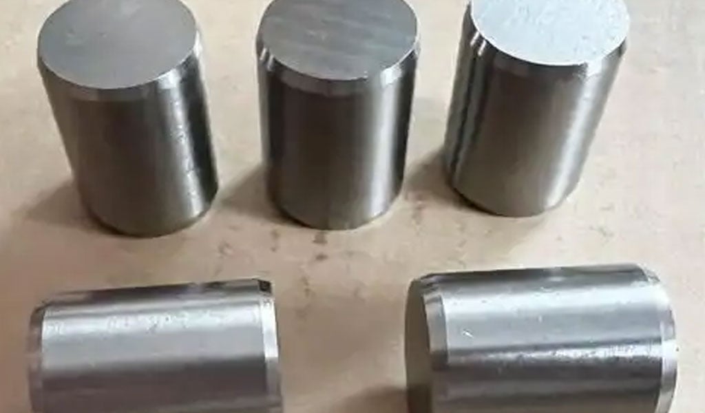
Dowel Pins: Overview and Definition
A dowel pin is a solid, cylindrical fastener with no threading, typically inserted into pre-drilled holes to align or secure two or more components. Unlike bolts or screws, dowel pins do not rely on threads for fastening; instead, they depend on a tight interference or slip fit to maintain positional accuracy. Their simplicity belies their critical role in precision engineering, where even minor misalignment can lead to mechanical failure. Dowel pins are distinguished by their uniform diameter, often machined to tight tolerances, and their ends, which may be chamfered, rounded, or tapered to facilitate insertion. The ASME B18.8.2 standard, last updated in 2020, provides detailed specifications for dowel pins, ensuring consistency and reliability in industrial applications.
Dowel pins are employed in diverse contexts, from aligning machine components during assembly to joining wooden furniture pieces or securing concrete slabs in masonry. Their versatility stems from their availability in various materials—such as stainless steel, alloy steel, aluminum, titanium, and wood—and their ability to withstand shear forces without deforming. In mechanical assemblies, dowel pins often serve as pivots, hinges, or shafts, while in jigs and fixtures, they act as locators to hold parts in precise positions. The ASME B18.8.2 standard categorizes dowel pins into specific types based on their design and intended use, which we will explore in detail.
Types of Dowel Pins Under ASME B18.8.2
The ASME B18.8.2 standard recognizes several types of dowel pins, each tailored to specific applications and installation methods. These include hardened ground machine dowel pins, unhardened ground dowel pins, and other variations such as grooved dowel pins. Below, we examine these types, their distinguishing features, and their typical uses.
Hardened Ground Machine Dowel Pins
Hardened ground machine dowel pins are precision-engineered fasteners designed for high-strength, wear-resistant applications. These pins are heat-treated to increase hardness, typically to a Rockwell C scale of 47-58, and ground to exacting tolerances. ASME B18.8.2 specifies two diameter series for these pins: the Standard Series and the Oversize Series.
- Standard Series: These pins have a basic diameter 0.0002 inches (0.005 mm) over the nominal diameter. For example, a 1/4-inch (0.250-inch) nominal diameter pin would range from 0.2500 to 0.2502 inches. This slight oversizing ensures a press fit in initial installations, where the pin is driven into a hole slightly smaller than its diameter, creating an interference fit that resists movement under load.
- Oversize Series: Intended for replacement or repair purposes, these pins have a basic diameter 0.001 inches (0.025 mm) over the nominal diameter (e.g., 0.2510 to 0.2512 inches for a 1/4-inch pin). The larger size accommodates worn or enlarged holes, restoring a tight fit without requiring re-drilling.
The ends of hardened ground machine dowel pins are typically rounded or crowned on one side and slightly pointed or chamfered on the other, aiding insertion and driving. These pins excel in applications requiring precise alignment, such as in dies, molds, and machine tools, where they resist shear forces and maintain positional accuracy under high loads.
Unhardened Ground Dowel Pins
Unhardened ground dowel pins, also covered by ASME B18.8.2, are produced from commercial wire or rod material, ground to size without heat treatment. These pins lack the hardness of their hardened counterparts, making them less suited to high-wear environments but more cost-effective for lighter-duty applications. Both ends are chamfered, typically at a 25-degree angle, to ease insertion into holes. Tolerances for unhardened pins are slightly less stringent than for hardened pins, with a diameter tolerance of +0.0002 to 0.000 inches and a length tolerance of ±0.010 inches. These pins are commonly used in furniture assembly, woodworking, and low-stress mechanical alignments.
Grooved Dowel Pins
Grooved dowel pins, another subtype under ASME B18.8.2, feature longitudinal grooves that enhance their functionality. The standard defines several groove types, including Type A, Type C, and others, each with specific groove configurations:
- Type A: Features three full-length tapered grooves, ideal for locking applications where the pin compresses upon insertion and expands to grip the hole walls.
- Type C: Has three parallel grooves extending one-quarter of the pin’s length, providing moderate compression and retention.
Grooved dowel pins are typically made from low-carbon steel with a zinc-plated finish for corrosion resistance. They are used in assemblies where a semi-permanent fit is desired, such as in automotive components or machinery requiring occasional disassembly.
ASME B18.8.2 Size Chart for Dowel Pins
The ASME B18.8.2 standard provides detailed dimensional data for dowel pins, including nominal diameters, lengths, and tolerances. Below is a comprehensive size chart for hardened ground machine dowel pins (Standard Series), extracted and adapted from the standard. Dimensions are in inches, and tolerances reflect the precision required for industrial applications.
Table 1: Hardened Ground Machine Dowel Pins (Standard Series) – ASME B18.8.2
| Nominal Diameter | Diameter Range (in) | Length (in) | Length Tolerance (in) | Press Hole Size (in) |
|---|---|---|---|---|
| 1/16 (0.0625) | 0.0626 – 0.0628 | 1/4, 5/16, 3/8 | ±0.010 | 0.0620 – 0.0625 |
| 1/8 (0.125) | 0.1251 – 0.1253 | 1/4, 3/8, 1/2, 5/8 | ±0.010 | 0.1245 – 0.1250 |
| 3/16 (0.1875) | 0.1876 – 0.1878 | 3/8, 1/2, 5/8, 3/4 | ±0.010 | 0.1870 – 0.1875 |
| 1/4 (0.250) | 0.2501 – 0.2503 | 1/2, 5/8, 3/4, 1 | ±0.010 | 0.2495 – 0.2500 |
| 5/16 (0.3125) | 0.3126 – 0.3128 | 5/8, 3/4, 1, 1-1/4 | ±0.010 | 0.3120 – 0.3125 |
| 3/8 (0.375) | 0.3751 – 0.3753 | 3/4, 1, 1-1/4, 1-1/2 | ±0.010 | 0.3745 – 0.3750 |
| 1/2 (0.500) | 0.5001 – 0.5003 | 1, 1-1/2, 2, 2-1/2 | ±0.010 | 0.4995 – 0.5000 |
| 5/8 (0.625) | 0.6251 – 0.6253 | 1-1/2, 2, 2-1/2, 3 | ±0.010 | 0.6245 – 0.6250 |
| 3/4 (0.750) | 0.7501 – 0.7503 | 2, 2-1/2, 3, 4 | ±0.010 | 0.7495 – 0.7500 |
| 1 (1.000) | 1.0001 – 1.0003 | 2-1/2, 3, 4, 5 | ±0.010 | 0.9995 – 1.0000 |
Notes:
- Lengths increase in increments: 1/16-inch steps up to 3/8 inch, 1/8-inch steps from 3/8 to 1 inch, 1/4-inch steps from 1 to 2-1/2 inches, and 1/2-inch steps above 2-1/2 inches.
- Press hole sizes are recommended for mild steels and cast iron; softer materials (e.g., aluminum) may require a 0.0005-inch reduction.
- Oversize Series pins follow the same length increments but have diameters 0.001 inches larger than nominal.
This table serves as a practical guide for engineers selecting dowel pins for press-fit applications, ensuring compatibility with mating holes and structural integrity under load.
Dowel Pins vs. Roll (Spring) Pins: A Detailed Comparison
While dowel pins are solid and rigid, roll pins (also known as spring pins) are hollow, slotted cylinders that compress during insertion and expand to grip hole walls. Both serve as fasteners, but their designs and applications differ significantly. Below, we compare these two pin types across multiple dimensions, supported by scientific analysis and practical examples.
Design and Structure
Dowel pins, as per ASME B18.8.2, are solid rods with a uniform diameter, often ground to tolerances as tight as ±0.0002 inches. Their ends may be chamfered, rounded, or grooved, depending on the type, but they lack internal flexibility. This rigidity ensures a stable, fixed connection capable of withstanding shear forces perpendicular to the pin’s axis. For instance, a 1/4-inch hardened dowel pin can resist double shear forces exceeding 10,000 psi in alloy steel, depending on its material properties.
Roll pins, conversely, are made from sheet metal (e.g., high-carbon steel, stainless steel, or alloy 6150) rolled into a cylindrical shape with a longitudinal slot. This slot allows the pin to compress when inserted into a hole and spring back, creating radial pressure against the hole walls. The ASME B18.8.2 standard also covers spring pins, defining their dimensions and tolerances, typically with a diameter tolerance of +0.002 to -0.004 inches for slotted types. This elasticity makes roll pins self-retaining, eliminating the need for precise interference fits.
Material Properties
Dowel pins are available in a wide range of materials, each chosen for specific environmental and mechanical requirements:
- Stainless Steel (e.g., 303, 316, 416): Offers corrosion resistance for use in humid or chemical-laden environments, such as marine equipment or food processing machinery.
- Alloy Steel: Heat-treated for hardness and strength, ideal for high-load applications like automotive engines or aerospace components.
- Wood: Used in furniture and carpentry for aesthetic and cost reasons, though less durable under mechanical stress.
Roll pins are predominantly metallic, with common materials including:
- High-Carbon Steel: Provides a balance of strength and flexibility, often hardened to 40-50 Rockwell C.
- Stainless Steel: Resists corrosion while maintaining spring properties, suitable for outdoor machinery.
- Alloy 6150: Combines toughness and elasticity, used in heavy-duty rotating assemblies.
The material choice affects fatigue life, with dowel pins excelling in static applications and roll pins better suited to dynamic, vibrational loads due to their spring action.
Installation and Removal
Installation methods highlight a key distinction. Dowel pins are typically press-fit or slip-fit:
- Press Fit: Requires a hole slightly smaller than the pin diameter (e.g., 0.2495 inches for a 0.2501-inch pin), driven in with a hammer or press. This creates a permanent or semi-permanent joint, removable with a punch or puller.
- Slip Fit: Uses a hole slightly larger than the pin (e.g., 0.2505 inches), allowing hand insertion and easy removal, common in temporary alignments.
Roll pins require a punch or spring-pin tool to compress and insert them into a hole matching their nominal diameter (e.g., 0.250 inches). The pin’s expansion creates a tight fit, making removal more challenging—often requiring a punch to collapse the pin again. This self-retention is advantageous in assemblies subject to vibration, reducing the risk of loosening.
Applications
Dowel pins are favored in applications requiring precise alignment and load-bearing capacity:
- Machine Assembly: Aligning gears, bearings, or housings in engines, where tolerances of ±0.001 inches are critical.
- Woodworking: Securing joints in furniture, such as table legs, with wooden or metal dowels.
- Masonry: Joining concrete blocks, where large-diameter steel dowels absorb lateral forces.
Roll pins excel in dynamic environments:
- Rotating Assemblies: Securing pulleys or shafts in motors, where vibration resistance is essential.
- Automotive: Fastening components like brake calipers or suspension parts, benefiting from their lightweight, flexible design.
- Hinges: Acting as pivots in mechanisms requiring occasional disassembly.
Performance Under Load
The solid structure of dowel pins gives them superior shear strength. For example, a 1/4-inch alloy steel dowel pin can withstand a double shear load of approximately 14,000 pounds, calculated as:
Shear Strength=2×Cross-Sectional Area×Shear Stress=2×(π×(0.125)2)×80,000psi≈14,137lb
Roll pins, being hollow, have lower shear strength (e.g., ~5,000 pounds for a 1/4-inch high-carbon steel pin) but excel in radial retention and fatigue resistance. Their spring action absorbs vibrational energy, reducing wear in cyclic loading conditions, as described by the fatigue life equation:
Nf=(σf′−σm/σa)1/b
where Nf N_f Nf is the number of cycles to failure, σf′ \sigma_f’ σf′ is the fatigue strength coefficient, σm \sigma_m σm is the mean stress, σa \sigma_a σa is the stress amplitude, and b b b is the fatigue exponent.
Cost and Availability
Dowel pins are generally more affordable due to their simple, solid construction and widespread production. A 1/4-inch stainless steel dowel pin might cost $0.10-$0.50 each in bulk, depending on material and tolerance. Roll pins, requiring rolling and slotting processes, are slightly more expensive (e.g., $0.20-$0.75 each), though still economical for mass production. Both are widely available, with dowel pins offered in ASME, DIN, and ISO standards, and roll pins conforming to ASME B18.8.2 or ISO 8752.
Table 2: Dowel Pins vs. Roll (Spring) Pins – Comparative Analysis
| Feature | Dowel Pins (ASME B18.8.2) | Roll (Spring) Pins |
|---|---|---|
| Structure | Solid cylinder, chamfered/rounded ends | Hollow, slotted cylinder |
| Diameter Tolerance | +0.0002 to 0.000 in (Standard Series) | +0.002 to -0.004 in |
| Material | Stainless steel, alloy steel, wood, etc. | High-carbon steel, stainless steel |
| Installation | Press or slip fit, hand/press tools | Punch insertion, compresses |
| Removal | Pull/punch, relatively easy | Punch, more difficult |
| Shear Strength | High (e.g., 14,000 lb for 1/4-in steel) | Moderate (e.g., 5,000 lb) |
| Vibration Resistance | Low, requires tight fit | High, spring action absorbs energy |
| Applications | Static alignment, load-bearing | Dynamic assemblies, vibration |
| Cost (per unit) | $0.10-$0.50 | $0.20-$0.75 |
Scientific Considerations and Engineering Implications
From an engineering perspective, the choice between dowel pins and roll pins hinges on the specific mechanical requirements of the assembly. Dowel pins, with their high shear strength and precision, are ideal for applications where alignment accuracy and structural integrity are paramount. Their solid construction minimizes deflection under load, as governed by the equation for beam deflection in shear:
δ=FL/AG
where δ \delta δ is deflection, F F F is the shear force, L L L is the length, A A A is the cross-sectional area, and G G G is the shear modulus. For a solid dowel pin, A A A is maximized, reducing δ \delta δ.
Roll pins, however, leverage their elastic properties to maintain retention in less precise holes, with radial pressure calculated as:
P=E⋅t⋅(ΔD)/D
where P P P is the radial pressure, E E E is the modulus of elasticity, t t t is the wall thickness, ΔD \Delta D ΔD is the compression, and D D D is the diameter. This makes them resilient in assemblies with thermal expansion or misalignment.
Conclusion
Consider a CNC machine table requiring precise alignment of fixture plates. Hardened dowel pins (e.g., 1/2-inch diameter, 2-inch length) ensure sub-thousandth-inch accuracy, resisting lateral forces from cutting operations. In contrast, a lawnmower’s blade assembly might use 1/4-inch roll pins to secure the blade to a rotating shaft, where vibration resistance outweighs the need for absolute precision.
Dowel pins, as standardized by ASME B18.8.2, and roll pins represent two distinct approaches to fastening and alignment in engineering. Dowel pins offer unmatched strength and precision for static, high-load applications, while roll pins provide flexibility and retention in dynamic, vibrational environments. The choice between them depends on factors such as load conditions, installation constraints, and cost, with each type supported by rigorous standards and material science. The size chart and comparative analysis provided here equip engineers and designers with the data needed to make informed decisions, ensuring optimal performance in diverse mechanical systems.


The Detail Of BE-CU Cnc Machining Shop
BE-CU.COM – As an accomplished CNC machining Service Manufacturer and CNC shop, BE-CU Prototype has been specialized in OEM CNC lathing, custom CNC machining parts production and rapid CNC machining services China for over 35 years and always maintaining the highest standard in delivery speed and reliable quality of precision CNC manufacturing components. With the help of high-level technology and efficient equipment, as well as rigorous attitude, BE-CU passed the ISO9001:2015 quality certification, which supports the long-term development of CNC milling services, CNC turning services, CNC milling-turning, CNC drilling services, 3/4/5 axis machining, gear machining services, CNC machining China custom parts and service, small parts machining, etc.Our CNC machining products can be utilized in a broad range of industries. Contact us for email: [email protected]

-

3-Way Centrifugal Compressor Closed Impeller By 5 Axis Machining
-

3/4/5 Axis Precision Milling Custom Vehicle Parts
-

3D Flexible Welding Platform By Large Machining
-

3D Printed Inconel Exhaust Manifold
-

3D Printing And CNC Machining Custom Black PPS Valve
-

3D Printing Full Transparent Acrylic Lampshade Model
-

4 Axis CNC Machining Titanium Grade 5 Mobile Phone Buttons
-

4 Axis Machining Highly Transparent Acrylic LED Tunnel Light Lens