
Laser beam quality is a critical parameter in the design, application, and performance evaluation of laser systems. It quantifies how well a laser beam can be focused to a small spot size or how well it maintains collimation over long distances. One of the most widely accepted metrics for assessing laser beam quality is the M² factor, also known as the beam propagation factor or beam quality factor. The M² measurement provides a standardized way to compare the performance of a laser beam to that of an ideal Gaussian beam, which represents the theoretical limit of beam quality. This article provides a comprehensive exploration of the principles, methodologies, equipment, and applications of M² measurement for evaluating laser beam quality, presented in a rigorous and scientific manner.
Introduction to Laser Beam Quality
The quality of a laser beam is a measure of its ability to maintain a tight focus or propagate with minimal divergence. In many applications, such as laser cutting, medical procedures, optical communication, and scientific research, the beam quality directly influences the system’s efficiency and precision. A high-quality laser beam approaches the diffraction-limited performance of an ideal Gaussian beam, which has the smallest possible spot size and divergence for a given wavelength. However, real-world laser beams deviate from this ideal due to factors such as optical aberrations, thermal effects, and imperfections in the laser cavity or optics.
The M² factor, introduced by Anthony E. Siegman in the 1990s, is a dimensionless parameter that quantifies how closely a laser beam resembles an ideal Gaussian beam. An M² value of 1 indicates a perfect Gaussian beam, while higher values indicate poorer beam quality, with increased divergence or larger focal spot sizes. The M² measurement is now standardized by the International Organization for Standardization (ISO) under ISO 11146, which provides guidelines for measuring beam quality in a consistent and reproducible manner.
This article delves into the theoretical foundations of M², the experimental techniques for its measurement, the equipment required, and the practical considerations for achieving accurate results. It also discusses the applications of M² measurements in various fields, compares different measurement techniques, and provides detailed tables to aid in understanding the process.
Theoretical Background of M²
Gaussian Beam Propagation
To understand M², it is essential to first explore the propagation characteristics of an ideal Gaussian beam. A Gaussian beam is described by its electric field distribution, which follows a Gaussian function in the transverse plane. The intensity profile of a Gaussian beam is given by:
[ I(r, z) = I_0 \left( \frac{w_0}{w(z)} \right)^2 \exp \left( -\frac{2r^2}{w(z)^2} \right) ]
where:
- ( I(r, z) ) is the intensity at radial distance ( r ) and axial distance ( z ),
- ( I_0 ) is the peak intensity,
- ( w_0 ) is the beam waist radius (the minimum beam radius at ( z = 0 )),
- ( w(z) ) is the beam radius at distance ( z ), defined as:
[ w(z) = w_0 \sqrt{1 + \left( \frac{z}{z_R} \right)^2} ]
- ( z_R ) is the Rayleigh range, given by:
[ z_R = \frac{\pi w_0^2}{\lambda} ]
where ( \lambda ) is the wavelength of the laser light. The Rayleigh range represents the distance over which the beam radius increases by a factor of ( \sqrt{2} ).
The divergence angle ( \theta ) of a Gaussian beam in the far field is:
[ \theta = \frac{\lambda}{\pi w_0} ]
This relationship shows that a smaller beam waist results in a larger divergence angle, a fundamental property governed by the diffraction limit.
Definition of M²
The M² factor is defined as the ratio of the beam parameter product (BPP) of a real laser beam to that of an ideal Gaussian beam. The BPP is the product of the beam waist radius ( w_0 ) and the far-field divergence angle ( \theta ):
[ \text{BPP} = w_0 \theta ]
For an ideal Gaussian beam, the BPP is:
[ \text{BPP}_{\text{Gaussian}} = \frac{\lambda}{\pi} ]
For a real beam, the M² factor is:
[ M^2 = \frac{\text{BPP}{\text{real}}}{\text{BPP}{\text{Gaussian}}} = \frac{w_0 \theta}{\lambda / \pi} ]
Thus, M² quantifies how much the beam deviates from the diffraction-limited case. An M² of 1 corresponds to an ideal Gaussian beam, while higher values indicate a beam with poorer focusability or greater divergence.
Physical Interpretation of M²
The M² factor can also be expressed in terms of the beam waist and divergence relative to a Gaussian beam. For a real beam, the beam radius ( w(z) ) and divergence angle ( \theta ) are scaled by ( M^2 ):
[ w(z) = w_0 \sqrt{1 + \left( \frac{M^2 z}{z_R} \right)^2} ]
[ \theta = M^2 \frac{\lambda}{\pi w_0} ]
This shows that a beam with ( M^2 > 1 ) has a larger beam waist or greater divergence than an ideal Gaussian beam with the same wavelength.
Principles of M² Measurement
The measurement of M² involves determining the beam width at multiple points along the propagation axis and fitting the data to a model of beam propagation.
According to ISO 11146, the beam width is defined as the second moment of the intensity distribution, often referred to as the D4σ diameter (four times the standard deviation of the intensity distribution). The M² measurement process typically involves the following steps:
- Measurement of Beam Widths: The beam width is measured at several positions along the propagation axis, typically around the beam waist and in the far field.
- Fitting to a Propagation Model: The measured beam widths are fitted to a hyperbolic function that describes the beam propagation, allowing the determination of the beam waist, divergence, and M².
- Correction for Non-Gaussian Beams: For non-Gaussian beams, additional considerations, such as astigmatism or higher-order modes, may be accounted for in the analysis.
Beam Width Definitions
The beam width is a critical parameter in M² measurements. Several definitions of beam width are used, depending on the beam profile and measurement technique:
- D4σ Diameter: The second-moment diameter, defined as:
[ D4\sigma = 4 \sqrt{\frac{\int I(x, y) (x – \bar{x})^2 , dx , dy}{\int I(x, y) , dx , dy}} ]
This is the standard definition used in ISO 11146 because it accounts for the full intensity distribution, including low-intensity wings.
- 1/e² Diameter: The diameter at which the intensity drops to ( 1/e^2 ) (approximately 13.5%) of the peak intensity. This is suitable for Gaussian or near-Gaussian beams but may underestimate the width of beams with significant non-Gaussian components.
- FWHM (Full Width at Half Maximum): The width at which the intensity is half the peak value. This is less commonly used for M² measurements due to its sensitivity to beam shape.
Beam Propagation Model
The beam propagation is modeled using the following equation for the beam radius squared:
[ w^2(z) = w_0^2 + M^4 \left( \frac{\lambda}{\pi w_0} \right)^2 (z – z_0)^2 ]
where:
- ( w_0 ) is the beam waist radius,
- ( z_0 ) is the location of the beam waist,
- ( \lambda ) is the wavelength,
- ( M^2 ) is the beam quality factor.
By measuring ( w(z) ) at multiple points and fitting the data to this equation, the parameters ( w_0 ), ( z_0 ), and ( M^2 ) can be determined.
Measurement Techniques for M²
Several techniques are used to measure M², each with its advantages and limitations. The choice of method depends on the laser’s wavelength, power, beam size, and the desired accuracy. The following sections describe the most common methods.
Knife-Edge Method
The knife-edge method is a simple and cost-effective technique for measuring beam width. A sharp edge (e.g., a razor blade) is translated across the beam, and the transmitted power is measured as a function of the edge’s position. The beam width is derived from the power profile, typically assuming a Gaussian or near-Gaussian beam shape.
Procedure:
- Position the knife edge perpendicular to the beam propagation axis.
- Translate the edge across the beam and record the transmitted power using a photodetector.
- Repeat the measurement at multiple positions along the propagation axis.
- Calculate the beam width using the second-moment or 1/e² definition.
- Fit the beam width data to the propagation model to determine M².
Advantages:
- Simple and inexpensive setup.
- Suitable for a wide range of wavelengths and power levels.
- Robust against noise in low-intensity beam wings.
Limitations:
- Assumes a symmetric beam profile, which may not hold for non-Gaussian beams.
- Requires precise alignment of the knife edge.
- Less accurate for beams with complex mode structures.
Slit-Scan Method
The slit-scan method is similar to the knife-edge method but uses a narrow slit instead of an edge. The slit is scanned across the beam, and the transmitted power is measured to determine the beam profile.
Procedure:
- Position a slit (typically 10–100 µm wide) perpendicular to the beam.
- Scan the slit across the beam and measure the transmitted power.
- Repeat at multiple axial positions.
- Compute the beam width and fit to the propagation model.
Advantages:
- Provides direct measurement of the beam profile.
- Suitable for low-power lasers.
Limitations:
- Slit width must be much smaller than the beam diameter, which can be challenging for small beams.
- Sensitive to alignment errors.
- Less effective for high-power lasers due to potential damage to the slit.
CCD/CMOS Camera Method
The use of charge-coupled device (CCD) or complementary metal-oxide-semiconductor (CMOS) cameras is one of the most common methods for M² measurement, especially for visible and near-infrared lasers. The camera captures the beam’s intensity distribution directly, allowing for detailed analysis of the beam profile.
Procedure:
- Use a focusing lens to create a beam waist (optional, depending on the beam size).
- Position the camera at multiple points along the beam path, typically using a translation stage.
- Capture the beam intensity distribution at each position.
- Calculate the second-moment beam width from the intensity data.
- Fit the beam width data to the propagation model to determine M².
Advantages:
- Provides a full 2D intensity profile, enabling analysis of non-Gaussian or astigmatic beams.
- High resolution and accuracy.
- Suitable for a wide range of beam sizes and wavelengths (with appropriate cameras).
Limitations:
- Requires careful calibration of the camera’s pixel size and dynamic range.
- Expensive compared to knife-edge or slit-scan methods.
- May require attenuation for high-power lasers to avoid sensor damage.
Beam Profiler with Moving Lens
A beam profiler with a moving lens combines a focusing lens with a detector (e.g., a CCD camera or a single-pixel detector). The lens is moved along the beam axis to measure the beam width at different positions, simulating the effect of propagation.
Procedure:
- Place a focusing lens in the beam path to create a waist.
- Move the lens along the beam axis and measure the beam width at the detector.
- Use the lens law to relate the measured beam widths to the propagation model.
- Calculate M² from the fitted data.
Advantages:
- Compact setup, as the detector remains stationary.
- Suitable for automated measurements.
- Can be used with a variety of detectors.
Limitations:
- Requires precise knowledge of the lens focal length and position.
- May introduce errors due to lens aberrations.
- Less suitable for highly divergent beams.
Comparison of Measurement Techniques
The following table compares the main M² measurement techniques based on key parameters:
| Technique | Principle | Advantages | Limitations | Typical Applications | Cost |
|---|---|---|---|---|---|
| Knife-Edge | Measures power blocked by a moving edge | Simple, inexpensive, robust for low-intensity wings | Assumes symmetric profile, less accurate for complex beams | General-purpose, low-cost measurements | Low |
| Slit-Scan | Measures power through a moving slit | Direct profile measurement, suitable for low-power lasers | Requires small slit width, sensitive to alignment | Low-power lasers, small beams | Low-Moderate |
| CCD/CMOS Camera | Captures 2D intensity distribution | High resolution, suitable for non-Gaussian beams, detailed profile analysis | Expensive, requires calibration, may need attenuation for high power | High-precision measurements, complex beams | High |
| Beam Profiler with Lens | Uses moving lens to measure beam widths | Compact, automated, versatile with different detectors | Lens aberrations, requires precise lens positioning | Automated systems, industrial applications | Moderate-High |
Equipment for M² Measurement
Accurate M² measurement requires specialized equipment tailored to the laser’s characteristics (e.g., wavelength, power, beam size). The following components are commonly used:
Laser Source
The laser source is the device under test. Its properties, such as wavelength, power, and coherence, influence the choice of measurement equipment. Common laser types include:
- Gas Lasers (e.g., HeNe, CO₂): Typically produce high-quality beams with M² close to 1.
- Solid-State Lasers (e.g., Nd:YAG, fiber lasers): May have M² values ranging from 1 to several, depending on the cavity design.
- Semiconductor Lasers (e.g., diode lasers): Often have higher M² values due to astigmatism or multimode operation.
Beam Attenuators
High-power lasers may require attenuation to prevent damage to detectors or cameras. Common attenuators include:
- Neutral density filters
- Beam splitters
- Polarizing optics
Focusing Optics
A lens is often used to create a beam waist, which simplifies M² measurements by reducing the beam size and increasing the divergence angle. The lens must have low aberrations and be appropriate for the laser’s wavelength.
Detectors
Detectors measure the beam’s intensity or power. Common types include:
- Photodiodes: Used in knife-edge or slit-scan methods for power measurements.
- CCD/CMOS Cameras: Used for direct imaging of the beam profile.
- Pyroelectric Detectors: Suitable for pulsed lasers or infrared wavelengths.
Translation Stages
Motorized or manual translation stages are used to move the detector or lens along the beam axis. High-precision stages are critical for accurate measurements, especially for small beams or short Rayleigh ranges.
Beam Profilers
Commercial beam profilers integrate detectors, optics, and software to automate M² measurements. Examples include:
- Thorlabs M² Measurement System
- Ophir-Spiricon M²-200s
- Coherent ModeMaster
These systems typically include a CCD camera or scanning slit, a translation stage, and software for data analysis.
Practical Considerations for Accurate M² Measurements
Achieving accurate and reproducible M² measurements requires careful attention to experimental setup and data analysis. The following considerations are critical:
Beam Alignment
The beam must be well-aligned with the measurement system to avoid errors due to tilt or offset. Misalignment can lead to apparent astigmatism or incorrect beam width measurements. Alignment can be checked using a reference beam or alignment laser.
Detector Calibration
Detectors, especially CCD/CMOS cameras, must be calibrated for pixel size, linearity, and dynamic range. Overexposure or saturation can distort the intensity profile and lead to inaccurate M² values.
Background Subtraction
Background noise, such as ambient light or detector dark current, must be subtracted from the measurements to ensure accurate beam width calculations. This is particularly important for low-intensity beams or measurements in the beam wings.
Number of Measurement Points
ISO 11146 recommends measuring the beam width at least 10 points along the propagation axis, with at least 5 points within one Rayleigh range of the beam waist and 5 points in the far field. More points improve the accuracy of the fit but increase measurement time.
Handling Non-Gaussian Beams
For non-Gaussian beams, the second-moment beam width (D4σ) is preferred, as it accounts for the full intensity distribution. However, for beams with significant high-order modes or aberrations, additional analysis (e.g., mode decomposition) may be required to fully characterize the beam.
Astigmatism and Beam Asymmetry
Astigmatic beams, where the beam waist locations or divergence angles differ in the x and y directions, require separate M² measurements for each axis. The final M² value is often reported as the average or the larger of the two values, depending on the application.
Environmental Factors
Vibrations, air turbulence, and temperature fluctuations can affect beam propagation and measurement accuracy. Measurements should be conducted in a controlled environment, and long-term stability of the laser should be verified.
Applications of M² Measurements
M² measurements are critical in a wide range of applications, as they provide insight into the performance and suitability of a laser for specific tasks. Some key applications include:
Laser Material Processing
In laser cutting, welding, and additive manufacturing, beam quality affects the precision and efficiency of the process. A low M² (close to 1) is preferred for applications requiring tight focusing, such as micro-machining, while higher M² values may be acceptable for processes like welding, where a larger spot size is desirable.
Optical Communications
In free-space optical communication, a low M² ensures minimal beam divergence over long distances, maximizing signal strength and reducing losses. M² measurements are used to optimize beam collimation and alignment.
Medical Applications
In laser surgery and ophthalmology, beam quality is critical for achieving precise tissue ablation or focusing within the eye. M² measurements help ensure that the laser meets the required specifications for safety and efficacy.
Scientific Research
In fields such as nonlinear optics, laser spectroscopy, and quantum optics, M² measurements are used to characterize laser beams for experiments requiring high beam quality, such as optical trapping or frequency conversion.
Laser Design and Development
M² measurements are used during the design and testing of laser systems to optimize cavity design, select appropriate optics, and verify performance. For example, fiber lasers may require M² measurements to assess the impact of fiber bending or splicing on beam quality.
Advanced Topics in M² Measurement
Higher-Order Modes and Mode Decomposition
Real laser beams often contain higher-order modes (e.g., Hermite-Gaussian or Laguerre-Gaussian modes), which contribute to an M² value greater than 1. Mode decomposition techniques, such as those based on wavefront sensing or interferometry, can be used to analyze the modal content of the beam and provide a more detailed understanding of its quality.
M² for Pulsed Lasers
For pulsed lasers, the M² measurement must account for temporal variations in the beam profile. This may involve averaging the beam width over multiple pulses or using high-speed detectors to capture the beam profile during a single pulse.
M² for Astigmatic and Elliptical Beams
Astigmatic beams require separate M² measurements for the x and y axes. The measurement setup must allow for independent analysis of each axis, often using cylindrical lenses or rotated detectors. Elliptical beams may also require specialized analysis to account for asymmetry in the beam profile.
Limitations of M²
While M² is a powerful metric, it has limitations. It assumes a beam that can be approximated by a Gaussian propagation model, which may not hold for highly multimode or aberrated beams. Additionally, M² does not provide information about the beam’s spatial or temporal coherence, which may be critical in some applications.
Standards and Guidelines
The ISO 11146 series provides detailed guidelines for M² measurement, including:
- ISO 11146-1: General principles for measuring beam widths, divergence, and M².
- ISO 11146-2: Methods for measuring beams with astigmatism or asymmetry.
- ISO 11146-3: Guidelines for measuring beams with complex or non-Gaussian profiles.
These standards ensure consistency and reproducibility in M² measurements across different laboratories and applications.
Comparison of M² Values for Common Laser Types
The following table provides typical M² values for various laser types, illustrating the range of beam quality encountered in practice:
| Laser Type | Typical M² Range | Comments |
|---|---|---|
| Helium-Neon (HeNe) | 1.0–1.1 | Near-Gaussian, high-quality beam due to single-mode operation. |
| Nd:YAG (Solid-State) | 1.1–10 | M² depends on cavity design and mode control (e.g., single-mode vs. multimode). |
| Fiber Laser | 1.0–2.0 | High beam quality for single-mode fibers; higher M² for multimode fibers. |
| Diode Laser | 1.5–50 | Often astigmatic or multimode, leading to higher M² values. |
| CO₂ Laser | 1.1–5.0 | Beam quality varies with resonator design and gas mixture. |
| Excimer Laser | 10–100 | Poor beam quality due to large beam size and multimode operation. |
Conclusion
Advances in laser technology and measurement techniques are driving improvements in M² measurement. Some emerging trends include:
- Automated M² Systems: Fully automated systems with integrated beam profilers and software for real-time M² analysis.
- Ultrafast Laser Measurements: Techniques for measuring M² in ultrafast lasers with complex temporal and spatial profiles.
- Wavefront Sensing: Combining M² measurements with wavefront analysis to provide a more comprehensive characterization of beam quality.
- Machine Learning: Using machine learning algorithms to analyze beam profiles and predict M² values for complex beams.
The M² factor is a fundamental metric for assessing laser beam quality, providing a standardized way to compare real beams to the ideal Gaussian case. By measuring the beam width at multiple points along the propagation axis and fitting the data to a propagation model, M² quantifies the beam’s focusability and divergence. Various measurement techniques, such as the knife-edge, slit-scan, and CCD camera methods, offer flexibility and trade-offs in terms of cost, accuracy, and complexity. With applications spanning laser processing, communications, medicine, and research, M² measurements are essential for optimizing laser performance and ensuring suitability for specific tasks.
The Detail Of BE-CU Laser Cutting Company
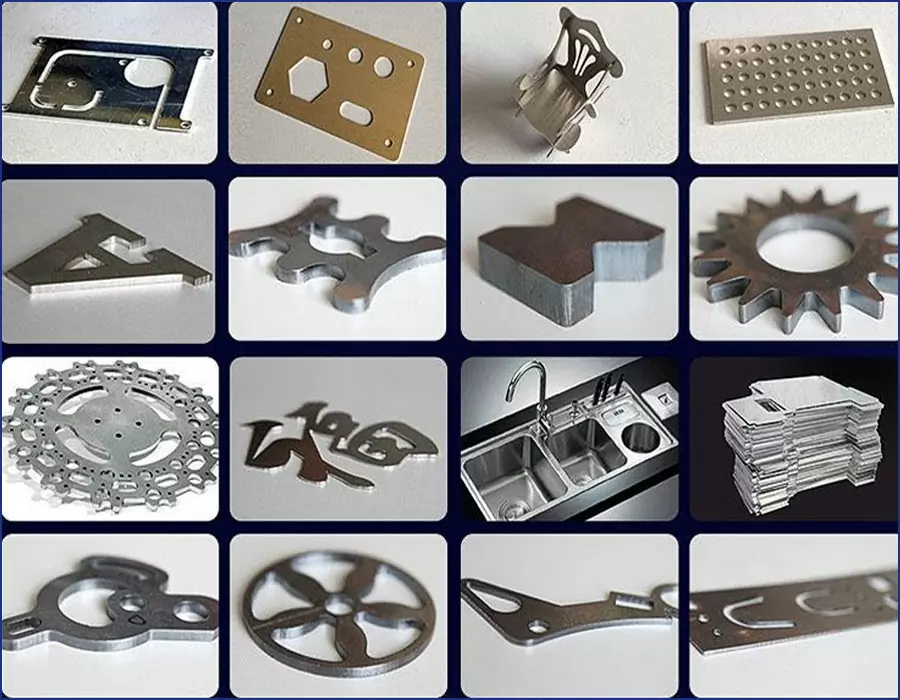
BE-CU.COM Laser Cutting provides services to a wide network of industries and markets. BE-CU is uniquely positioned to Laser Cut, Laser Engrave, Precision CNC Machine and Precision Finish Grind parts and components.We use large format industrial laser cutting machines that are extremely precise with up to .001” tolerance. Not only we cut and engrave your project, we are ready to answer any questions you may have about the process and give you expert advice.
So, reach out even if you’re unsure of your specific need or if you think you may require a different type of manufacturing service(as laser cutting medical parts). Laser cutting service by BE-CU makes ordering your parts simple. Just upload your CAD files onto the platform for an instant price and lead time. Our mission is to save engineers’ time for value-adding activities.
-
Etching LED EMC Packaging Bracket
-
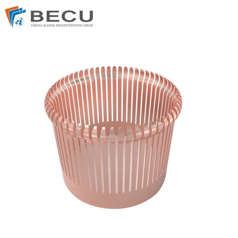
Etching Low Resistivity Copper 110 Contact Rings
-

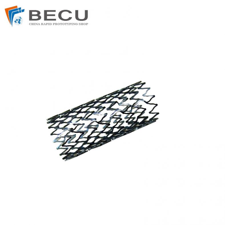
Laser Cut Nitinol Stent For Bile Duct
-
Stents For Carrying Valves And Venous Valve Replacement Devices
-
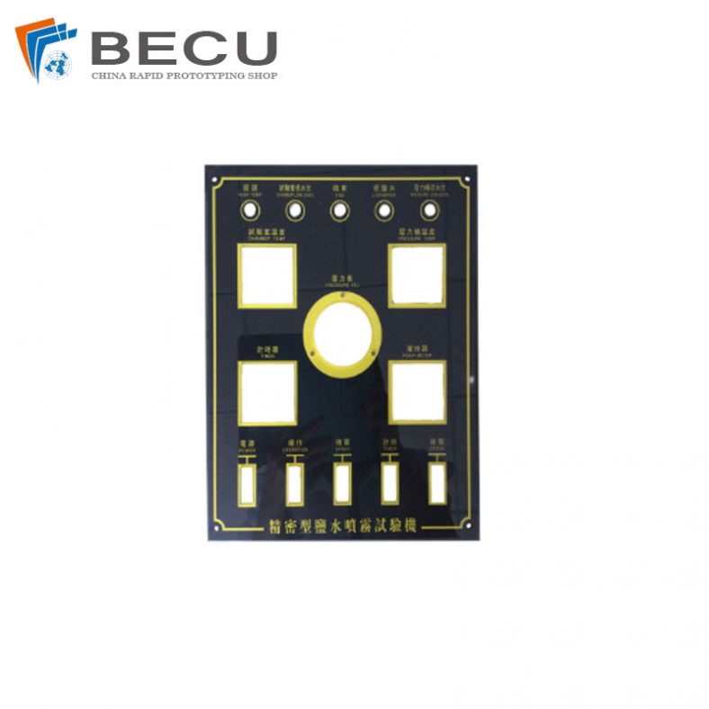
Laser Cutting PC Anti-Static Membrane Switch
-
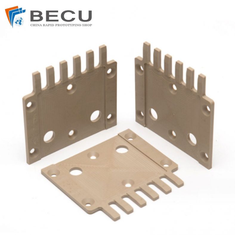
Precision Engraving Special-Shaped Natural Color PEEK Parts
-

Acrylic Laser Cut Signs
-

Acrylic Laser Cut Earrings