
Computer-Aided Design (CAD) has revolutionized the way engineers and designers create complex mechanical components. One such component that benefits from CAD’s precision and versatility is the involute gear. In this article, we will delve into the process of creating involute gears using CAD and 3d software. From understanding the fundamentals of involute gears to the step-by-step process of designing them, this guide aims to provide a comprehensive overview for both beginners and experienced CAD users.
Fundamentals of Involute Gears
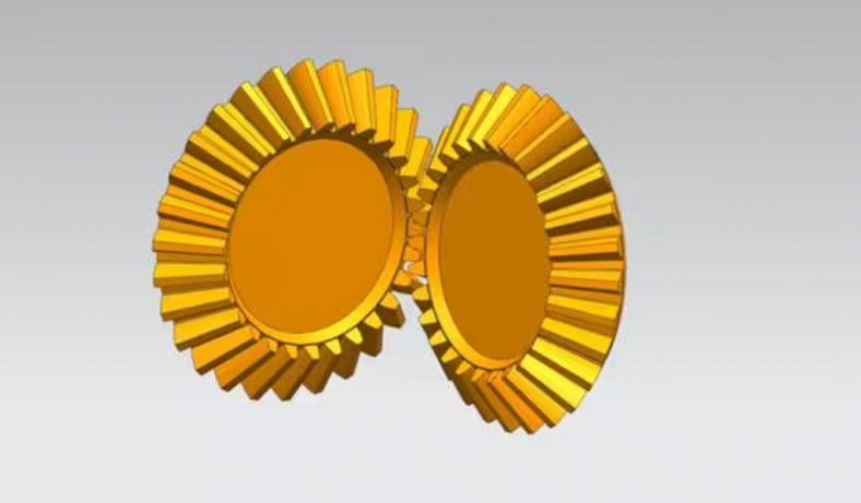
Before we dive into the CAD design process, let’s explore the fundamentals of involute gears. An involute gear is a toothed mechanical component that transmits rotational motion and torque between two shafts. Its unique tooth profile is based on the mathematical involute curve, which ensures smooth and efficient gear engagement.
Key parameters that define an involute gear include the pitch diameter, number of teeth, pressure angle, and module or diametral pitch.
Choosing the Right CAD Software
The journey of creating involute gears begins with selecting the appropriate CAD software. Leading options in the CAD realm include SolidWorks, AutoCAD, Fusion 360, and Inventor. Each software package offers a range of tools and capabilities that cater to different user preferences and design requirements. A CAD software with robust 3D modeling features is essential for accurately crafting the intricate geometries of involute gears.
Step-by-Step Guide to Creating Involute Gears
Creating involute gears using CAD involves a step-by-step process that combines mathematical calculations with precise modeling techniques. Follow this comprehensive guide to create involute gears in your chosen CAD software:
Step 1: Prepare Your Workspace
Launch your CAD software and create a new part/document to begin your gear design.
Step 2: Define Gear Parameters
Determine the essential parameters of the gear:
- Pitch Diameter (D): The diameter of the theoretical pitch circle.
- Number of Teeth (N): The total number of teeth on the gear.
- Pressure Angle (α): The angle between the line of action and a tangent to the pitch circle.
- Module (m) or Diametral Pitch (P): The module represents the gear’s size and is the ratio of the pitch diameter to the number of teeth. Diametral pitch is the number of teeth per unit length along the pitch diameter.
Step 3: Calculate Involute Points
Use mathematical equations to calculate the coordinates of points along the involute curve. These points will form the basis of your gear teeth profiles. The involute curve’s parametric equations can be derived using trigonometry and calculus.
Step 4: Construct the Involute Curve
Connect the calculated points to create the involute curve. This curve represents the tooth profile of your gear. Depending on your CAD software, you can use tools like splines, arcs, or lines to connect the points and create a smooth curve.
Step 5: Generate Gear Teeth Profiles
Extrude or sweep a tooth thickness profile along the involute curve to create the gear teeth. The tooth thickness profile is typically a rectangle that represents the thickness of the teeth. Make sure to extend the teeth slightly beyond the base circle to avoid interference.
Step 6: Mirror and Circular Pattern
Create a single tooth and then use mirroring and circular patterning functions to generate the complete set of teeth around the gear’s circumference. This ensures uniformity and accuracy in the gear design.
Step 7: Add Fillets and Chamfers
Enhance the strength and aesthetics of your gear by adding fillets to the edges and chamfers to the corners of the teeth. This step helps to reduce stress concentrations and improve the durability of the gear.
Step 8: Incorporate Shaft Hole
If your gear is intended to be mounted on a shaft, create a hole at the center of the gear for the shaft to pass through. This hole allows the gear to be securely attached to the shaft.
Step 9: Additional Features
Depending on your specific application, you might need to add additional features such as keyways, set screw holes, or other components. Incorporate these features to match your design requirements.
Step 10: Check for Interferences
Use the interference detection tools provided by your CAD software to ensure that there are no clashes or interferences between the gear you’ve designed and other components in your assembly.
Step 11: Save and Export
Save your CAD file in the appropriate format for your software. Consider exporting the gear model in formats like STL if you plan to 3D print it or in other formats suitable for further use.
Step 12: Advanced Techniques
If you’re comfortable with the basics, you can explore advanced gear design concepts like helical gears, gear assemblies, and gear ratios to tackle more complex engineering challenges.
Remember that the exact steps and tools might vary based on the CAD software you’re using. Additionally, accurate involute gear design often requires a deep understanding of mathematical principles, so be prepared to invest time in both CAD techniques and gear theory.
Benefits of Using CAD for Involute Gear Design
Using Computer-Aided Design (CAD) for involute gear design offers numerous benefits that contribute to efficient, precise, and optimized gear creation. Here are some of the key advantages:
- Precision and Accuracy: CAD tools enable designers to create involute gears with high precision and accuracy. Mathematical calculations can be translated directly into digital models, minimizing errors associated with manual drawing methods.
- Efficient Prototyping: CAD allows for the rapid creation of virtual prototypes, reducing the need for physical prototypes during the design phase. This accelerates the design process and saves time and resources.
- Iterative Design: CAD software permits easy modification of designs. Designers can quickly make adjustments to gear parameters, tooth profiles, or other features and observe their effects in real-time simulations.
- Visual Simulation: CAD platforms offer simulation capabilities that enable designers to visualize how gears interact within an assembly. This aids in identifying potential interferences and ensuring smooth gear engagement.
- Design Validation: Through simulations, designers can evaluate the performance of gears under different load conditions, speeds, and torque values. This helps validate gear designs before moving to the manufacturing stage.
- Parametric Design: CAD software allows for parametric modeling, where changes to one aspect of the design automatically update related components. This feature is particularly useful when altering gear specifications.
- Customization: CAD tools facilitate the customization of gears to suit specific applications. Designers can modify gear ratios, pressure angles, or other parameters to meet unique engineering requirements.
- Complex Geometry: Involute gears often feature complex geometries. CAD software can handle intricate shapes and curves with precision, enabling the creation of accurate tooth profiles.
- Documentation and Communication: CAD models can be used to generate detailed technical drawings and documentation. This documentation is vital for communicating design intent to manufacturing teams and other stakeholders.
- Material and Stress Analysis: Some CAD programs provide tools for material selection and stress analysis. This helps designers choose suitable materials and assess gear strength and durability under various conditions.
- Interchangeability: CAD models can be stored digitally, allowing for easy retrieval and reuse. Designers can also modify existing models to create variations or new gear designs.
- Digital Archives: CAD files serve as a digital archive of the design process. This is invaluable for future reference, design revisions, and reverse engineering.
- Collaboration: CAD software supports collaboration among design teams by allowing multiple designers to work on the same project simultaneously. This enhances productivity and fosters innovation.
- 3D Printing and Prototyping: CAD models can be exported for 3D printing and rapid prototyping. This facilitates physical testing and validation of gear designs before manufacturing.
- Cost Savings: Using CAD can lead to cost savings by reducing the number of physical prototypes, minimizing errors, and optimizing gear designs before production.
CAD significantly enhances the gear design process by providing precise modeling, simulation capabilities, customization options, and efficient collaboration. By leveraging the benefits of CAD, designers can create involute gears that are not only functional but also optimized for performance, durability, and specific application requirements.
Congratulations; you have a gear!
Creating involute gears in CAD is a meticulous yet rewarding process that showcases the power of modern engineering design tools. From the foundational concepts of involute gears to the intricate steps of CAD-based design, this guide has equipped you with the knowledge needed to embark on your journey of crafting precise and efficient gear components. By mastering the art of CAD-based gear design, engineers and designers can contribute to innovations across industries that rely on smooth and reliable mechanical power transmission.
For all your manufacturing and mechanical design needs, including involute gears, reach out to Be-Cu today. Fictiv is the ultimate manufacturing partner, providing an intelligent platform to upload your 3D models or 2D drawings for an instant quote and DfM feedback. We are experts in CNC Machining, Injection Molding, Urethane Casting, and 3D Printing.