
In this paper, according to the nature and characteristics of stamping processing of electric water heater liner, the automatic production line for stamping and loading and unloading based on industrial robots developed for stamping products can not only adapt to the current stamping automation processing environment, but also steadily improve production efficiency. It also has a certain degree of versatility in the industry, and has a wide range of compatibility with punches and molds.
Stamping Automatic Loading And Unloading Production Line
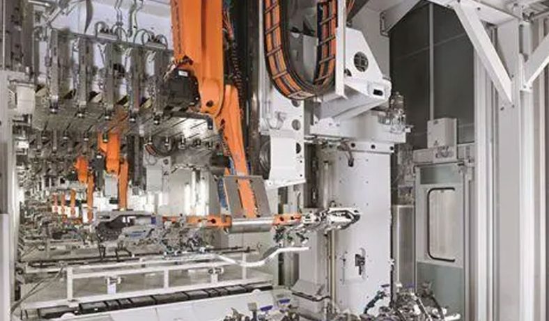
Overall scheme wiring diagram of stamping automation production line
The robot stamping and unloading production line is an automatic production line for electric water heater liner end cap stamping, which is mainly composed of 1 set of PLC master control system, 4 sets of punching machines, 2 sets of hydraulic presses, 1 3kg manipulator (flange machine), 1 10kg manipulator (automatic feeding machine), 7 GSK-RB08 robots and other related equipment. The overall scheme wiring is shown in Figure 1. Through the integration of the robot system, the whole process of the water heater liner punching and unloading production is automated.
General requirements of loading and unloading robot system
The electric water heater liner loading and unloading robot stamping production line requires the automation of the entire system workflow. Specific requirements include the following aspects:
Press Requirements
The sum of the height of the two adjacent punching machines and the height of the lower die of the die should not exceed 300mm.
Mold automation requirements
- The mold requires that the upper and lower molds be removed smoothly, and there should be no material jamming.
- The height of the mold opening space of the other mold (excluding the movable space for positioning) should be greater than 100mm as much as possible, and special structures can be used in special cases.
- The mold should have a guiding and positioning device and have enough guiding space.
- The product should be turned over as little as possible. Because the robot can only take and unload material from the front, each additional flip needs to be supplemented with a flip table and a robot.
- Considering compatibility, the flipping process of multiple products should be designed in the same process as much as possible.
Site Requirements
When the center distance between the two machines is less than 2200mm, the robot is facing the machine tool, the swing arm angle can be less than 180°, and the speed is faster. When the center distance between the two machines is greater than 2200mm, the robot needs to be placed in the middle of the machine in the opposite direction, and the swing arm angle is 180°.
Requirements for the control system
The control system has reasonable structure design, stable operation, high control precision, high reliability of transmission scheme and low noise.
Economic requirements
Try to combine the needs of the user unit, and carry out the transformation on the basis of not changing the original punching mechanism and installation site of the user unit, so as to reduce the investment cost.
Process flow of inner tank manufacturing
In the stamping stage of the liner, on the basis of preparing the molds for each process, the 10kg manipulator (automatic feeding machine) automatically grabs the blank with a suction cup at the discharge position to the conveyor belt, and then passes the detector to detect the blank (electric water heater metal The round plate cover is divided into two positions and stacked together. When the plate cover is stacked, it is coated with anti-rust oil.
When the suction cup is sucked, it may cause multiple plate covers to stick together, but only one can be grabbed at a time.) A single plate cover is allowed to be transferred to the reclaiming position of robot 5. When there are many, the 10kg manipulator will take it back to the conveyor belt and wait for the next feeding; Robot 5 feeding: after the blank on the feeding machine reaches the reclaiming position , Robot 5 grabs the blank (plate cover) to punch the hydraulic press E and hydraulic press F respectively (the production line is divided into two branches); Robot 4 loads and unloads:
After the hydraulic press E is stamped, the semi-finished product is positioned by the blanking device. , Robot 4 grabs the semi-finished product for punching press A; Robot 3 loads and unloads: After punching A is completed, Robot 3 grabs the semi-finished product for punching B; Robot 2 unloads:
After punching B is completed, Robot 2 grabs the semi-finished product for punch C, wait for the 3kg manipulator (flange machine) to grab the flange of the water heater end cover and place it on the semi-finished end cover before punching; Robot 1 unloading: After punching C is completed, robot 1 grabs the finished product (the left end cover of the water heater) and lowers it Loading and unloading by robot 6: After the punching of hydraulic press F is completed, the semi-finished product that has been punched is positioned by the blanking device, and robot 6 grabs the semi-finished product for punching by punching machine D; Water heater right end cover) unloading.
Control System Design Of Stamping Production Line
In order to achieve the goals of fast running speed, accurate positioning and high efficiency in the production process, the automatic control of various equipment and their coordination and control are particularly important. The following mainly analyzes the design of the control system of the stamping production line.
Hardware design of the control system
The electronic control system of the stamping automatic production line is mainly composed of presses, robots and auxiliary equipment. The following two points need to be fully considered when designing the hardware of the control system: (1) The selection of process parameters of the three parts of the press, robots and auxiliary equipment The setting, coordination, and action coordination adjustment are coordinated by the control system to ensure the normal operation of the entire automatic stamping production line; (2) When designing the control system, it is necessary to combine the large area of the entire production line and the interval between each equipment. Comprehensive consideration of the characteristics of large size, involving many equipment, and complex overall system control.
According to the above analysis, based on the characteristics of this production line, in the hardware design of its control system, a distributed control system is selected. On the basis of realizing the overall control, each equipment can realize its own flexible control requirements, and can also effectively realize the control information and data. Effectively transfer between equipments, effectively solve the problem of wide distribution among equipments, and operate efficiently among the equipments in the entire production line.
The idea of the control scheme is to divide the automation system of the entire field device layer into two parts: robot automation control and punching machine automation control. As the control system of the control part of the robot, the line head PLC connects the frequency converters and robots of each unit through the bus and realizes data exchange with the PLC of the press through the coupler.
Similar to the control idea of the above-mentioned robot part, the automation part of the press uses PLC as the control system, and realizes the data exchange of each press PLC in the field through the bus, and distributes the distributed I/O, encoder, inverter, DC The governor, etc. are coordinated and connected.
Selecting a distributed control system is easy to expand and flexibly realize the increase and decrease of stamping processes. In addition, because of the simple wiring structure of this solution, it is easy to install and maintain, with high reliability and economical practicality.
Software design of control system
The software flow of the control system
After the system is powered on and the master control system completes the initialization operation, it will detect and judge whether the robot stamping machine tool and the non-standard operation machine are in a normal ready state. If they are all ready, wait for the command. The operator can switch between the automatic mode and the manual mode by flipping the switch. ; After the program enters the automatic mode, after the start switch is pressed, the entire production line enters the automatic operation state until the stop or reset button is pressed or there is a fault.
Program function design of system PLC
The PLC software composition mainly includes: manual function, automatic function, alarm query, fault handling, parameter modification. In order to meet the working conditions of the stamping production line and realize the humanized requirements of system control, the program function design of the system PLC needs to meet the following requirements: (1) To meet the manual control of a single action. (2) Automatic control of a working cycle. (3) Fault handling function and alarm function. (4) Online communication function. (5) Parameter modification function.
Human-computer interface
Once there is a fault in the system, the entire production line will stop working, the system will automatically enter the fault processing module, complete the system fault response according to the fault level through fault query, carry out fault alarm, and automatically generate an alarm log and display it on the touch screen.
System working rhythm and action cycle
For the convenience of analysis, taking the multi-process top cover as an example, the stamping production line is divided into six units: (1) The first station (stretching), which uses an automatic material rack for feeding, and two silos operate. (2) The second station (edge trimming) is in the same direction as the first station without turning over. (3) The third station (punching) is in the same direction as the second station without turning over. (4) The fourth station (flanging), in the same direction as the third station, without flipping. (5) The fifth station
(Riveting flange), in the same direction as the fourth station, without turning over. (6) Riveting blanking unit.
In general, the overall tact time of a production line is determined by the working time of the slowest operation unit, so to analyze the working rhythm of the production line, analyze the action cycle time including the robot unit.
It has been verified by actual production that the production line system is in continuous operation, with 5 projects on the upper cover + 2 projects on the lower cover, the production time is 10H, and the maximum output is about 4,000 pieces.
Design of production line safety system
The safety of the production site of the stamping automatic loading and unloading production line is one of the key issues to be considered when designing the system. In the design of control security, the system divides each machine tool and robot in the production line into several areas, and each machine tool and machine tool is used as a separate unit, so as to realize the effective control of each unit itself, avoid interference, and at the same time Anti-collision spaces are set up in the public spaces of machine tools and robots to improve the safety of equipment movements. In addition, in order to avoid the voltage change affecting the operation of the robot equipment, each punch is provided with a power socket connected from the main line, which cannot be connected from the punch. In addition, if there is an automatic material rack, a gas circuit should be provided for easy connection.
Conclusion
The stamping automatic production line control system designed in this paper realizes the fully automated production of the electric water heater liner pressure process, changes the traditional liner production method, and significantly improves the quality and production efficiency of liner products. The installation of this system in the electrical part And debugging electrical connection and field wiring should comply with national standards.
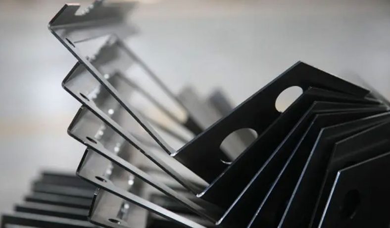
China Sheet Metal Fabrication Company
Sheet fabrication services for mild steel, high strength low alloy (HSLA) steel, cold/hot rolled steel, galvanized steel, stainless steel, aluminum, copper and brass. Capable of fabricating parts up to 12 ft. length and +/-0.001 in. tolerance. Various capabilities include contract manufacturing,custom stamping,edge rolling, forming,top laser cutting, roll bending and welding. Finishing and secondary services such as hardware installation, tapping, deburring, cleaning, heat treating, plating, anodizing and painting available. Sheet Metal Prototype and low to high volume production runs offered.
Suitable for commercial/residential architectural, aluminum brake shape parts, wall panel systems, brackets, general flashings, rails, call button plates and ship building component parts.If you want a specific material to be used in the sheet metal fabrication process, don’t hesitate to contact us!
-
Stainless Steel Sheet Metal Fabrication
-
Aluminum Sheet Metal Fabrication
-
Copper Sheet Metal Fabrication
-
Brass Sheet Metal Fabrication
-
Steel Sheet Metal Fabrication
-
Titanium Sheet Metal Fabrication
-
Galvanized Steel Sheet Metal Fabrication
-
Mild Steel Sheet Metal Fabrication
-
Bronze Sheet Metal Fabrication
Our Sheet Metal Fabrication Applications
Be-Cu prototype offers custom sheet metal fabrication for creating structures, machines, and parts that includes:
Our Case Studies Gallery Of Sheet Metal Fabrication Parts
If you need custom Sheet Metal Fabrication parts in China from a trusted supplier, look no further. Professional service from 10 to 100000+ parts,Whether you want a small series production or large quantities,Be-Cu Prototype scale precision Sheet Metal Fabrication services according to our customers needs, including pipe,plate and tube cutting. Contact us to see how we can help you! Get a quote today!
-
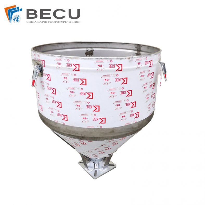
Sheet Metal Fabrication Injection Molding Machine Hopper
-
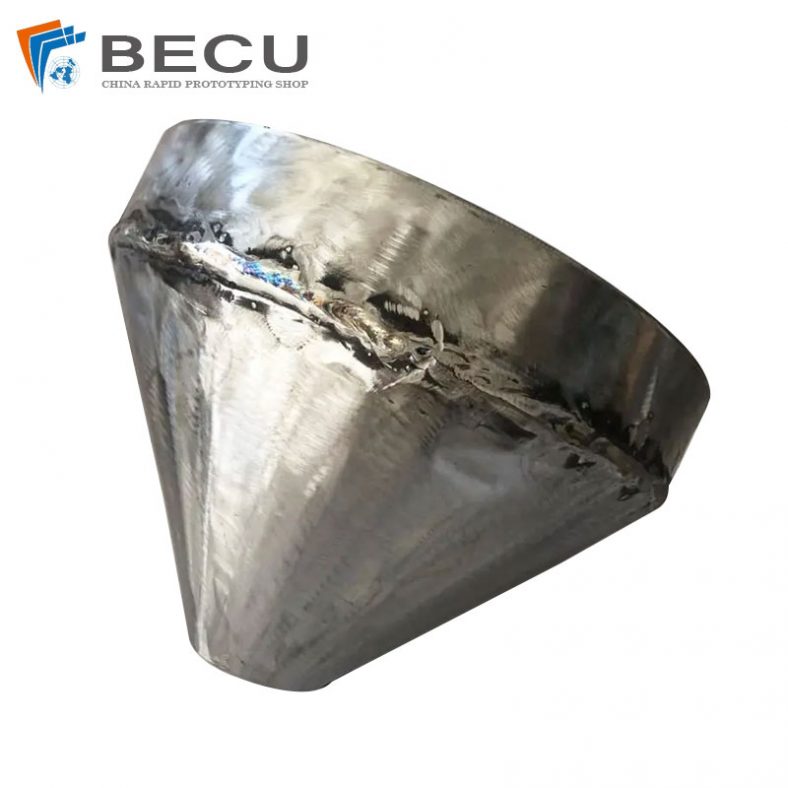
Sheet Metal Fabrication Funnel For Agricultural Machinery
-
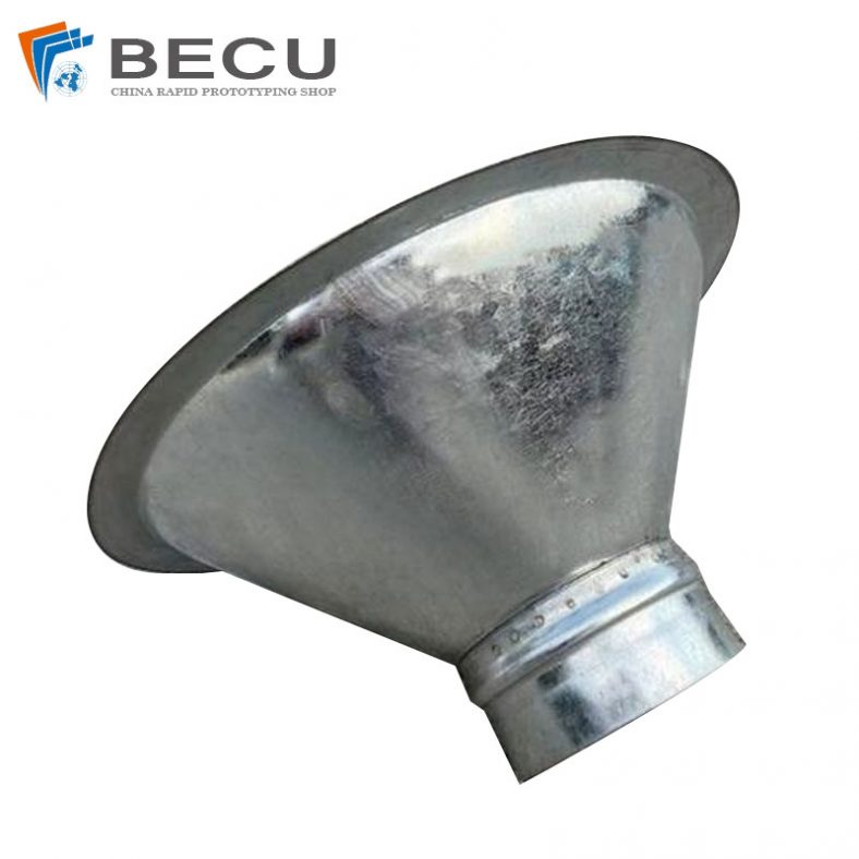
Sheet Metal Fabrication Galvanized Spiral Air Duct
-
PCS Fan Ductwork Sheet Metal Housing
-
Custom Sheet Metal Surgical Instrument Sterilization Box For Beauty Salon
-
Precision Fabrication Green Energy EV Charging Station Cabinet
-
TA1TA2 Alloy Sheet Metal Manufacturing Machinery Support Parts
-
Sheet Metal Fabrication Aluminum 5052 Medical Box For Fire Fighting