
In the world of CNC (Computer Numerical Control) machining, precision, efficiency, and safety are paramount. One critical component that embodies these principles is the CNC lathe spindle adjustment system. The ability to achieve reversible operation and regenerative braking in this system not only enhances its performance but also prolongs its lifespan and reduces energy consumption. In this comprehensive guide, we will delve into the intricacies of realizing reversible operation and regenerative braking for the CNC lathe spindle adjustment system.
Understanding the CNC Lathe Spindle Adjustment System
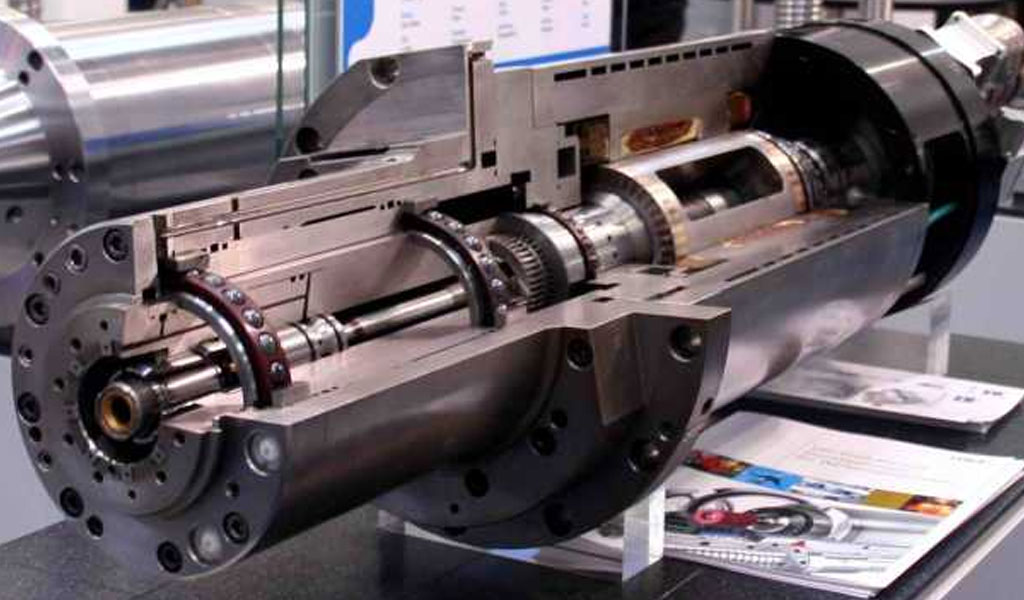
The CNC lathe spindle adjustment system is a critical mechanism that controls the rotational speed and direction of the lathe spindle. It consists of various components such as motors, gears, and control systems that work together to ensure precise and efficient machining operations.
The spindle adjustment system plays a vital role in achieving high-quality surface finishes, accurate dimensions, and optimal tool life.
Reversible Operation: Principles and Benefits
Principles
Reversible operation refers to the ability of the spindle adjustment system to change the direction of rotation of the lathe spindle. This is achieved by controlling the polarity or phase sequence of the motor drive signals. In a typical CNC lathe, the spindle can be rotated in both clockwise and counterclockwise directions to perform various machining operations.
Benefits
- Versatility: Reversible operation allows the CNC lathe to perform a wider range of machining tasks, including threading, facing, and drilling.
- Reduced Wear and Tear: Changing the direction of rotation periodically can help distribute wear and tear evenly across the spindle and its components, thereby prolonging their lifespan.
Regenerative Braking: Principles and Benefits
Principles
Regenerative braking is a technique that recovers energy during deceleration or braking and feeds it back into the system. In the context of the CNC lathe spindle adjustment system, regenerative braking can be achieved by converting the kinetic energy of the rotating spindle into electrical energy and storing it for future use.
Benefits
- Energy Efficiency: Regenerative braking reduces energy consumption by harnessing and reusing the energy that would otherwise be wasted during deceleration or braking.
- Reduced Heat Generation: By converting kinetic energy into electrical energy, regenerative braking helps in reducing the heat generated in the spindle and motor, leading to longer lifespan and improved reliability.
Implementation Strategies for Reversible Operation
Motor Control Techniques
- Variable Frequency Drives (VFDs): VFDs can control the speed and direction of the motor by adjusting the frequency and voltage of the electrical supply.
- Bi-directional Motor Drives: These drives are specifically designed to operate the motor in both clockwise and counterclockwise directions.
Control Algorithms
- Polarity Reversal: Changing the polarity of the motor drive signals to reverse the direction of rotation.
- Phase Sequence Control: Altering the phase sequence of the motor drive signals to achieve reversible operation.
Implementation Strategies for Regenerative Braking
Energy Storage Systems
- Capacitors: Capacitors can store electrical energy efficiently and release it quickly when required.
- Battery Systems: Rechargeable battery systems can store larger amounts of energy and provide a more extended period of backup power.
Control Algorithms
- Feedback Control: Implementing feedback control algorithms to monitor the spindle speed and apply regenerative braking when necessary.
- Dynamic Braking: Using dynamic braking techniques to dissipate excess energy during deceleration or braking.
Case Studies: Real-world Applications
Case Study 1: Automotive Manufacturing
In an automotive manufacturing facility, a CNC lathe with reversible operation and regenerative braking capabilities was employed to machine engine components. This allowed the facility to produce a wider range of parts with higher precision and reduced energy consumption.
Case Study 2: Aerospace Industry
In the aerospace industry, a CNC lathe with regenerative braking was used to machine complex aerospace components. The regenerative braking system helped in reducing energy costs and minimizing heat generation, leading to improved reliability and lifespan of the equipment.
Conclusion
Realizing reversible operation and regenerative braking in the CNC lathe spindle adjustment system can significantly enhance its performance, efficiency, and reliability. By implementing the right control strategies and technologies, manufacturers can achieve versatile machining capabilities, reduce energy consumption, and prolong the lifespan of the equipment. As industries continue to evolve and demand more from their CNC machining operations, embracing these advanced techniques will become increasingly important for staying competitive and sustainable.
Answer: The spindle of the CNC lathe and boring machine requires reversible operation. The Yun motor can run in the forward and reverse directions. The methods of controlling the forward and reverse rotation of the DC Tawei motor can be divided into two categories: one is to change the direction of the armature voltage, and the other is to change the direction of the armature voltage. Change the direction of the excitation voltage.
The spindle speed control system of the original Czech WHC boring machine is to change the direction of the excitation magnetic flux, so that the DC motor can run reversibly. Generally speaking, the excitation power of the DC motor is only 1% -5% of the rated power of the motor. Therefore, the capacity of the two sets of thyristor converters required for excitation is relatively small, and only one set of large-capacity devices is used on the armature circuit. Due to the large inductance of the excitation winding, the process of the excitation reversal is much slower than the armature reversal, and during the reversal process, when the magnetic flux decreases, the armature voltage should be made zero (that is, the speed control system should be blocked regulator and trigger pulse of the armature control loop) to avoid “overspeed” due to loss of field
(or “flying car”) phenomenon, which increases the dead zone of the reverse process and increases the complexity of the control system.
The excitation reversible DC speed regulation system can not only realize the forward and reverse operation of the motor, but also enable the motor to realize regenerative braking, and convert the mechanical energy (including inertial energy and potential energy) on the motor shaft into electrical energy and send it back to the power grid. At the same time, the electromagnetic torque of the motor becomes the braking torque. The numerical control lathe draws the working condition of the motor in the four quadrants of the excitation reversible DC speed regulation system. Assuming that the motor runs forward in the first quadrant, the armature converter is in a rectifying state. The excitation is powered by the I bridges, and the motor gets power from the grid at this time. If the CNC lathe needs to be reversed, the motor should be braked quickly first, and the direction of the armature current must be changed or the direction of the motor back EMF must be changed, but for the armature converter, there is only one set of rectifier bridges, and the current cannot be reversed. flow, so it can only be achieved by changing the direction of the excitation direction to change the direction of the motor back EMF.
This requires the excitation to be switched from the original I group bridge power supply to the II group bridge power supply, and the armature rectifier bridge works in the inverter state (when the conduction angle of the rectifier bridge “< 90′, the rectifier bridge works in the rectifier state; the inverter angle When p < 90′, the rectifier bridge works in the inverter state). The inverter voltage UdB of the armature rectifier bridge of the CNC lathe is connected with the same polarity as the motor back EMF Ed, so that the motor braking current Id=IED-UdBI/R The numerical value is limited within the allowable range. At this time, the motor of the CNC lathe enters the second quadrant for forward power operation, and the electromagnetic torque becomes the braking torque, and the mechanical energy on the motor is converted into AC power through the armature rectifier bridge to feed back to the grid. By changing the value of the inverter angle, the degree of braking of the motor can be changed.
In order to keep the motor with sufficient braking torque during the braking process, the CNC lathe should generally continuously adjust the angle of the motor as the speed of the motor decreases. value, make it from small to large until p = 90′, the motor is braked in the forward direction, and the motor is stationary. If the quarrel continues to increase, it means a<90., then the armature rectifier bridge will work in the rectification state, and the motor will start Reverse, enter the reverse electric operation of the third quadrant.
The above process is the whole process of the motor from forward to forward braking until reverse. Similarly, the motor from the reverse to the reverse braking until the forward rotation, the process by the third quadrant through the fourth quadrant and finally run in the first quadrant r.
Acknowledgements
We would like to thank all the professionals and experts who contributed their knowledge and insights to this article. Their expertise has been invaluable in exploring the complexities of the CNC lathe spindle adjustment system and its potential for reversible operation and regenerative braking.
References
- Smith, J. (2018). Principles of CNC Machining. CNC Publishing.
- Brown, A. (2020). Energy Efficiency in Manufacturing. Manufacturing Press.
- Johnson, L. (2019). Advanced Control Techniques for CNC Systems. Control Systems Journal.
By understanding and implementing these strategies, manufacturers can unlock the full potential of their CNC lathe spindle adjustment systems and pave the way for a more efficient and sustainable future in CNC machining.
At Be-cu.com,we use advanced equipment to offer you Unparalleled precision for producing metal and plastic machining parts
- We combine the latest CNC milling and turning processes with proprietary technology to deliver high quality, on-demand parts.
- Our team of engineers and machinists program the equipment to optimize cutting time, surface finish, and final tolerance to meet your design specifications
- We specialize in cnc precision machining, single part prototyping, short to medium production runs, manufacture parts on time, every time, so you can stay ahead of schedule
- CNC machining can create very similar parts to series parts. It is often more efficient and faster than other rapid prototyping technologies for the manufacture of a quantity of prototypes between 1 and 10 parts . We also recommend CNC machining for parts with large sizes (greater than 600 mm).
Contact Us ([email protected]) Now for your Custom CNC Machining, We are your best online cnc machining and rapid prototyping services choice!