
Fracture-controlled laser cutting, also known as thermal stress cracking or controlled fracture cutting, represents a specialized non-contact machining technique designed for processing brittle materials such as ceramics, glass, and certain semiconductors. Unlike traditional laser cutting methods that rely on material vaporization or melting, fracture-controlled laser cutting leverages thermal stresses induced by a laser beam to initiate and propagate a controlled crack through the material. This method offers high precision, minimal material waste, and superior edge quality, making it an essential technology in industries such as electronics, aerospace, and photonics. This comprehensive guide explores the principles, mechanisms, applications, and recent advancements in fracture-controlled laser cutting, providing a detailed examination of its scientific foundations, practical implementations, and comparative analyses with other cutting techniques.
The technique is particularly suited for materials that are prone to cracking under thermal or mechanical stress, where conventional mechanical cutting methods may result in poor surface quality, micro-cracks, or excessive tool wear. By inducing a controlled fracture, this method achieves clean cuts with minimal thermal damage, offering significant advantages over other laser-based techniques like fusion cutting or ablation. This article delves into the historical development, underlying physics, experimental parameters, and technological innovations, supported by detailed tables comparing recent results and methodologies.

Historical Background
The development of laser cutting technologies began in the 1960s following the invention of the laser by Theodore H. Maiman in 1960. Early laser cutting applications focused on vaporization and melting techniques, primarily for metals and polymers, using high-power CO₂ lasers. However, these methods proved less effective for brittle materials due to undesirable thermal effects such as micro-cracks and heat-affected zones (HAZ). The need for precision cutting of ceramics and glass in industries like microelectronics and optics spurred research into alternative approaches.
In the late 1980s and early 1990s, researchers began exploring laser-induced thermal stress as a means of cutting brittle materials. The controlled fracture technique emerged as a viable method, with early studies focusing on the use of CO₂ lasers to induce thermal gradients in glass and ceramics. By the early 2000s, advancements in laser technology, including the development of Nd:YAG and femtosecond lasers, expanded the capabilities of fracture-controlled cutting, enabling higher precision and the ability to process thicker substrates. Key publications, such as those by Tsai and Liou (2003), laid the groundwork for understanding the fracture mechanisms and optimizing cutting parameters.
Today, fracture-controlled laser cutting is recognized as a critical technique for processing advanced materials, with ongoing research aimed at improving control over crack propagation, integrating real-time monitoring systems, and exploring ultrashort pulse lasers for enhanced performance.
Principles of Fracture-Controlled Laser Cutting
Fundamental Mechanism
Fracture-controlled laser cutting relies on the principle of inducing thermal stresses in a brittle material to create a controlled crack that propagates along a predetermined path. Unlike traditional laser cutting, which removes material through melting or vaporization, this method uses the laser as a heat source to generate a localized temperature gradient. The process can be broken down into three primary stages:
- Initiation Stage: The laser beam heats a small area on the material’s surface, causing thermal expansion. The surrounding cooler material restricts this expansion, resulting in compressive stresses around the laser spot.
- Stable Growth Stage: As the laser moves along the cutting path, the heated area cools, leading to contraction and the development of residual tensile stresses. These stresses initiate a crack that propagates from the surface to the bottom of the material.
- Unstable Fracture Stage: If the tensile stresses become uniformly distributed through the material’s thickness, the crack may extend uncontrollably, potentially deviating from the desired path.
The crack propagation is controlled by carefully managing the laser’s power, speed, and spot size, as well as the material’s thermal and mechanical properties. The goal is to maintain stable crack growth, ensuring a clean and precise cut.
Thermal Stress Generation
The generation of thermal stresses is governed by the material’s response to the laser-induced temperature gradient. When a laser beam strikes the surface, it causes rapid heating, leading to thermal expansion. The surrounding material, which remains cooler, constrains this expansion, inducing compressive stresses. As the laser moves away, the heated area cools rapidly, contracting and generating tensile stresses. These tensile stresses are critical for crack initiation and propagation.
The stress distribution can be modeled using the following equation for thermal stress in a brittle material:
[ \sigma = \frac{E \alpha \Delta T}{1 – \nu} ]
Where:
- (\sigma) is the thermal stress,
- (E) is the Young’s modulus of the material,
- (\alpha) is the coefficient of thermal expansion,
- (\Delta T) is the temperature difference,
- (\nu) is Poisson’s ratio.
Finite element analysis (FEA) tools, such as ANSYS, are commonly used to simulate the temperature and stress distributions during the cutting process, providing insights into crack propagation behavior.
Crack Propagation and Control
The ability to control crack propagation is the hallmark of this technique. The crack follows the path of the laser beam, but its trajectory can deviate if the cutting speed is too high or the stress field is asymmetrical. To address this, advanced systems incorporate real-time crack detection and path correction using image processing and iterative learning control. For example, a CCD camera can capture the fracture contour, and the laser path is adjusted to minimize deviations from the desired trajectory.
The crack propagation speed is typically slower than the laser’s movement, leading to a lagging distance between the crack tip and the laser spot. This lag must be carefully managed to ensure precision, particularly when cutting curves or complex geometries.
Types of Fracture-Controlled Laser Cutting Techniques
Single-Laser Method
The single-laser method involves using a single laser beam, typically a CO₂ laser with a wavelength of 10.6 μm, to induce thermal stresses. The laser heats a small area along the cutting path, creating compressive stresses followed by tensile stresses as the material cools. This method is effective for thin substrates (e.g., glass or ceramics less than 5 mm thick) and is widely used due to its simplicity. However, its cutting speed is limited, typically below 10 mm/s, to ensure stable crack propagation.
Dual-Laser Method
For thicker substrates (e.g., alumina >10 mm), a dual-laser system is often employed. The first laser, typically a focused Nd:YAG laser (wavelength 1.06 μm), scores the material’s surface to create a shallow groove. A second, defocused CO₂ laser then applies thermal energy to the scored line, inducing a crack that propagates through the material. This method allows for cutting speeds up to 1.5 mm/s for thick ceramics, with improved control over crack propagation.
Ultrashort Pulse Laser Cutting
Recent advancements have introduced ultrashort pulse lasers (e.g., femtosecond or picosecond lasers) for fracture-controlled cutting. These lasers deliver pulses with durations on the order of 10s to 300 fs, minimizing thermal diffusion and reducing the heat-affected zone. The high repetition rate and low energy pulses create an elongated zone of energy deposition, inducing high mechanical stress for single-pass cutting of materials like 1 mm-thick soda-lime glass. This method is particularly effective for precise control of crack propagation in curved or complex paths.
Materials Suitable for Fracture-Controlled Laser Cutting
Fracture-controlled laser cutting is primarily used for brittle materials with low thermal conductivity and high brittleness. Common materials include:
- Glass: Soda-lime glass, borosilicate glass, and chemically strengthened glass for displays and optical components.
- Ceramics: Alumina (Al₂O₃), zirconia (ZrO₂), and silicon carbide (SiC) for electronic substrates and structural components.
- Semiconductors: Silicon and gallium arsenide for microelectronics.
- Other Brittle Materials: Marble, stone, and certain composites like carbon fiber-reinforced polymers.
The suitability of a material depends on its thermal expansion coefficient, Young’s modulus, and fracture toughness. Materials with high fracture toughness require higher laser power or dual-laser systems to achieve controlled fracture.
Experimental Parameters and Their Effects
The quality and efficiency of fracture-controlled laser cutting depend on several experimental parameters, including laser power, cutting speed, spot size, pulse duration, and repetition rate. These parameters influence the temperature gradient, stress distribution, and crack propagation behavior.
Laser Power
Higher laser power increases the temperature gradient, leading to greater thermal stresses. However, excessive power can cause uncontrolled cracking or material vaporization, reducing cut quality. Typical power ranges for CO₂ lasers are 50–100 W for thin substrates and up to 200 W for thicker materials.
Cutting Speed
Cutting speed is a critical factor, as it determines the rate of heat input and cooling. Speeds above 10 mm/s may lead to crack deviation or incomplete fracture, while speeds below 1 mm/s ensure stable crack growth but reduce throughput. For ultrashort pulse lasers, speeds of 1–2 mm/s are common for high-precision cuts.
Spot Size
A larger spot size distributes heat over a wider area, reducing the risk of thermal damage but potentially decreasing precision. Conversely, a smaller spot size (e.g., 0.127 mm for CO₂ lasers) enhances precision but may limit the depth of penetration.
Pulse Duration and Repetition Rate
For ultrashort pulse lasers, pulse duration and repetition rate significantly affect the cutting process. Shorter pulses (e.g., 300 fs) minimize thermal diffusion, while high repetition rates (e.g., 500 kHz) ensure continuous energy deposition for stable crack propagation.
| Parameter | Single-Laser (CO₂) | Dual-Laser (Nd:YAG + CO₂) | Ultrashort Pulse Laser |
|---|---|---|---|
| Laser Power (W) | 50–100 | 60 (each laser) | 10–50 (pulse energy in μJ) |
| Cutting Speed (mm/s) | <10 | 1–1.5 | 1–2 |
| Spot Size (μm) | 127–373 | 32 (Nd:YAG), 373 (CO₂) | 10–50 |
| Pulse Duration | Continuous Wave | Continuous Wave | 300 fs–10 ps |
| Repetition Rate | N/A | N/A | 100–500 kHz |
| Material Thickness | <5 mm | >10 mm | 0.5–2 mm |
| Applications | Glass, thin ceramics | Thick ceramics | Glass, semiconductors |
Note: Values are approximate and based on typical experimental setups reported in literature.
Fracture Mechanics and Stress Analysis
Stress Distribution Analysis
Finite element analysis (FEA) is widely used to model the stress distribution during fracture-controlled laser cutting. The laser-induced temperature gradient creates a complex stress field, with compressive stresses near the laser spot transitioning to tensile stresses as the material cools. The stress field around the crack tip is critical for controlling propagation. The J-integral method, which quantifies the energy release rate at the crack tip, is often used to analyze crack stability.
The stress field can be described by:
[ \sigma_{ij} = \frac{K}{\sqrt{2\pi r}} f_{ij}(\theta) + \text{higher-order terms} ]
Where:
- (\sigma_{ij}) is the stress tensor,
- (K) is the stress intensity factor,
- (r) and (\theta) are polar coordinates relative to the crack tip,
- (f_{ij}(\theta)) are angular functions.
Fractography and Surface Analysis
Fractographic analysis using scanning electron microscopy (SEM) reveals the micro-mechanisms of fracture. The fracture surface typically exhibits four regions:
- Laser Evaporation Region: A small area where material is vaporized by the laser.
- Smooth Fracture Region: Characterized by stable crack growth.
- Intergranular Fracture Region: Resulting from anisotropic thermal expansion.
- Transgranular Fracture Region: Indicative of unstable fracture.
These regions provide insights into the cutting process and help optimize parameters for improved surface quality.
Applications of Fracture-Controlled Laser Cutting
Electronics and Microelectronics
Fracture-controlled laser cutting is extensively used in the electronics industry for cutting glass substrates for liquid crystal displays (LCDs) and semiconductor wafers. The technique’s ability to produce clean edges without micro-cracks is critical for high-precision components. For example, chemically strengthened glass for smartphone displays is cut using picosecond lasers with quenching to achieve smooth surfaces.
Aerospace and Structural Components
In aerospace, ceramics like alumina and zirconia are used for thermal barriers and structural components. Fracture-controlled laser cutting enables the production of complex shapes with high perpendicularity, reducing the need for post-processing.
Photonics and Optics
The optics industry relies on fracture-controlled laser cutting for shaping glass lenses and mirrors. The method’s precision and minimal thermal damage ensure optical clarity and performance.
| Industry | Materials | Key Requirements | Advantages of Fracture-Controlled Cutting |
|---|---|---|---|
| Electronics | Glass, silicon, GaAs | High precision, minimal micro-cracks | Clean edges, no post-processing |
| Aerospace | Alumina, zirconia, SiC | Complex shapes, high strength | High perpendicularity, minimal HAZ |
| Photonics | Borosilicate glass, quartz | Optical clarity, smooth surfaces | Minimal thermal damage, high precision |
| Medical | Ceramics, biocompatible glass | Biocompatibility, precision | Sterile cuts, smooth surfaces |
Comparison with Other Laser Cutting Techniques
Vaporization Cutting
Vaporization cutting uses a high-power laser to vaporize material along the cutting path. It is suitable for thin materials with low vaporization energy (e.g., plastics) but produces significant thermal damage and debris in brittle materials, making it less suitable than fracture-controlled cutting.
Fusion Cutting
Fusion cutting melts the material and removes it with an assist gas. While effective for metals, it often causes recast layers and HAZ in brittle materials, leading to reduced edge quality compared to fracture-controlled methods.
Reactive Fusion Cutting
This method combines melting with an oxygen-assisted chemical reaction to enhance cutting speed. It is primarily used for metals and is unsuitable for brittle materials due to excessive thermal effects.
Table 3: Comparison of Laser Cutting Techniques
| Technique | Mechanism | Materials | Advantages | Limitations |
|---|---|---|---|---|
| Fracture-Controlled | Thermal stress-induced cracking | Glass, ceramics, semiconductors | High precision, minimal HAZ | Slow speed, complex control |
| Vaporization | Material vaporization | Plastics, thin metals | Fast for thin materials | Debris, thermal damage |
| Fusion | Melting with assist gas | Metals, alloys | High speed, versatile | Recast layer, HAZ |
| Reactive Fusion | Melting with chemical reaction | Metals | Enhanced speed for metals | Unsuitable for brittle materials |
Note: Data compiled from multiple sources.
Recent Advancements and Innovations
Ultrashort Pulse Lasers
The adoption of femtosecond and picosecond lasers has revolutionized fracture-controlled cutting. These lasers minimize thermal diffusion, enabling single-pass cutting of thin glass with high precision. Research has demonstrated successful cutting of 1 mm-thick soda-lime glass at 1 mm/s using low-energy pulses at 500 kHz.
Real-Time Crack Detection
Advanced systems now incorporate digital image processing and CCD cameras to monitor crack propagation in real time. Iterative path revision algorithms adjust the laser path to correct deviations, improving accuracy for complex geometries.
Hybrid Techniques
Combining laser cutting with mechanical pre-bending or water jet cooling enhances control over crack propagation. For example, pre-bending LCD glass substrates induces additional tensile stress, improving cutting efficiency.
Conclusion:Challenges and Limitations
Fracture-controlled laser cutting is a transformative technology for processing brittle materials, offering unparalleled precision and minimal thermal damage. Its applications span electronics, aerospace, and photonics, with ongoing advancements enhancing its capabilities. By understanding the underlying principles, optimizing experimental parameters, and addressing challenges, this technique continues to evolve, promising significant contributions to advanced manufacturing.
Crack Deviation
The lag between the crack tip and the laser spot can cause deviations, particularly in curved or asymmetrical cuts. This requires sophisticated control systems to maintain accuracy.
Limited Cutting Speed
Fracture-controlled cutting is inherently slower than other laser cutting methods, with speeds typically below 10 mm/s. This limits its use in high-throughput applications.
Material Constraints
The technique is limited to brittle materials with favorable thermal properties. Materials with high thermal conductivity or low brittleness are less suitable.
Future Directions
Ongoing research focuses on improving cutting speed through advanced laser sources and control systems. The integration of artificial intelligence and machine learning for real-time parameter optimization is a promising area. Additionally, the development of hybrid laser systems combining ultrashort pulses with traditional CO₂ lasers could enhance versatility.
The Detail Of BE-CU Sheet Metal Company
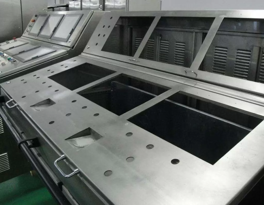
BE-CU is a professional and technical enterprise engaged in sheet metal fabrication, with over 2000 m2 sheet metal workshop and has one-stop service of industrial automation R&D, production, processing and sales.Custom manufacturer of sheet metal component assemblies made from stainless steel, aluminum and carbon steel. Offered in different specifications and features.Markets served include aerospace, lighting, medical, defense, semiconductor/electronics, capacitor, chemical processing and energy.Capable of maintaining dimensional tolerance up to +/-0.005 in. Capabilities include contract manufacturing, fabrication, machining, bending, milling, cutting, forming, drilling, fitting, assembly, notching, punching, rolling, turning, CNC press braking, flame and high definition plasma cutting, saw cutting, shearing, prototyping, high volume, short run and long run production and MIG, TIG and arc welding. Secondary services include Blanchard grinding, galvanizing and painting.
-
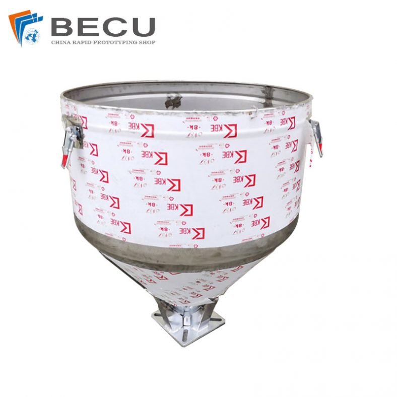
Sheet Metal Fabrication Injection Molding Machine Hopper
-
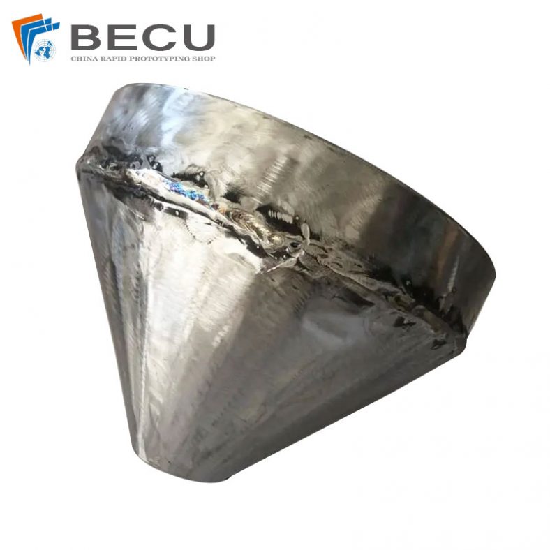
Sheet Metal Fabrication Funnel For Agricultural Machinery
-
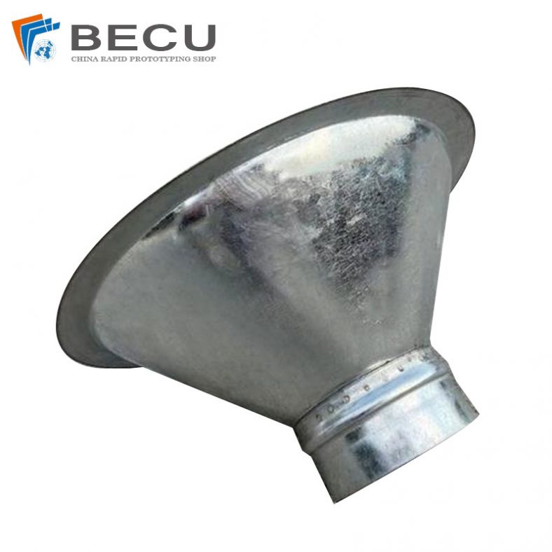
Sheet Metal Fabrication Galvanized Spiral Air Duct
-
PCS Fan Ductwork Sheet Metal Housing
-
Custom Sheet Metal Surgical Instrument Sterilization Box For Beauty Salon
-
Precision Fabrication Green Energy EV Charging Station Cabinet
-
TA1TA2 Alloy Sheet Metal Manufacturing Machinery Support Parts
-
Sheet Metal Fabrication Aluminum 5052 Medical Box For Fire Fighting