
3D printing requires 3D stereograms. 3D stereograms are available in many formats, and different software makes them in different formats. For example, common 3D printing formats are: STL, STP, IGS, OBJ, BREP, MAX, 3DM, 3DS, X_T, SKP, SLDPRT, PRT, ASM, F3D, FBX, RVT, WIRE and so on. The formats are different and other software may not open them. The same goes for 3D printers, which do not support many 3D stereogram formats and cannot be adapted to all the software on the market. The two most common formats used for 3D printing today are STL and STP, and to a certain extent it can be said that these two formats are necessary to print.
STL, STP, OBJ And IGS File Formats Explained
- STL — STL is an abbreviation for STereoLithography. It is the most common file format used in 3D printing as you can export it through many CAD software and printing systems. These files are only available in one colour and are therefore not suitable for multi-colour printer models.
- STP — STP (.step) files are better suited for curved designs or when you need an extremely accurate model. Though STEP is more complex, it contains more information than STL files and is easier to edit and repair after being exported. STEP is also often considered the best file format for sharing 3D models as it is a neutral file type. It is worth noting that the higher the model accuracy, the larger the file.
- IGS — A file format similar to STP. Both IGS (.iges) and STP files contain more detailed information than STL and OBJ files; however, IGES files are generally larger in size. So if you need to send CAD designs via email, using an STP format can often help reduce the attachment size.
- OBJ — After .STL, .OBJ is the leading 3D printing file format. It contains different information such as colour, temperature, texture, etc. Unlike STL files, it can store multi-colour information. Many 3D printers and 3D software support the .stl and .obj file formats
- .Gcode — .gcode, also known as .g or .gco, is a file format in which G-code instructions are stored. Slicing programs are used to create it. These programs convert CAD models into G-code that your 3D printer can understand.
- .3MF — 3MF (short for 3D Manufacturing Format) was first created by Microsoft in 2015. At the time, their goal was to simplify the printing process when using Windows 10. It is an XML-based data format that is also open source. Compared to .STL, .3MF stores more aspects of a 3D model (colours, textures, materials, etc.).
- VRML — VRML stands for Virtual Reality Modelling Language. It is the latest form of file format compared to STL. It can only store one UV colour model at a time, which makes it suitable for coloured 3D models. It is not as popular as STL, but it provides colour related information which makes it more useful when working with coloured models.
- AMF — AMF stands for Additive Manufacturing File Format. It is also an XML-based data file that can store a wide range of colours. These files are compressible and you can reduce them to half their original size. They can store a large amount of information related to an object, for example, its texture, metadata, constellations and materials. Although this format can store much more information than the STL format, it is still not widely used.
- FBX — FBX (which stands for Filmbox) is a proprietary file format owned by Autodesk for over 10 years. The .fbx file format is used when people need to share data between different Autodesk programs. It helps to improve workflow and is therefore widely used in game development.
STL vs STP vs IGS – The Difference Of STL-STP-IGS
What Is Step?
STEP (Standard Exchange of Product data model) is a standard developed by the International Organization for Standardization (ISO) to describe product information throughout the product life cycle. It was developed by Sub-Committee 4 (SC4) of the International Organization for Standardization (ISO) Technical Committee on Industrial Automation and Integration (TC184), officially designated ISO-10303, and provides a system-neutral mechanism for the exchange and sharing of product data. The nature of this description makes it suitable not only for the exchange of documents but also as a basis for implementing and sharing product databases and archives. The STEP standard has been taken to industrial applications in developed countries. Its application has significantly reduced the cost of exchanging information during the product life cycle, improved the efficiency of product development and become an . It is an important basic standard and an important tool to maintain the competitiveness of enterprises.
The STEP standard is both a product information modelling technology and a software implementation technology based on an object-oriented approach. It supports the exchange and sharing of information throughout the life cycle of a product from design to analysis, manufacturing, quality control, testing, production, use, maintenance and disposal, and aims to provide a method and technology for the representation and implementation of product data and information that is independent of any specific system and can be completely described.Note:
- The conversion to igs,stl format files can only be viewed, not modified.
- The conversion to igs, stl format files can only be viewed, not modified, whereas with the step format the parameters can be modified, which helps the data exchange to be more realistic.
What Is STL?
The STL file format is an interface protocol developed by 3D SYSTEM in 1988 as a 3D graphics file format for rapid prototyping techniques. There are two types of STL files: ASC domain format and binary format ASC domain format.
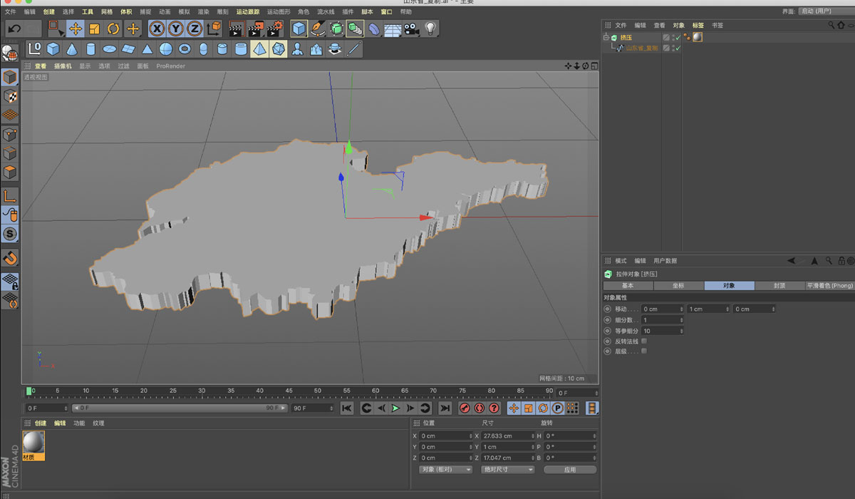
The process of STL model reconstruction is as follows: firstly, the triangle topology of the STL model is reconstructed; secondly, the basic geometric elements are decomposed from the overall model; the regular geometric elements are reconstructed; and then these geometric elements are created. Then the topological relationship between these geometric elements is established; finally the whole model is reconstructed.
The most commonly used inversion software are: ProE, UG NX, CATIA, solidworks, lmageware, Geomagic Studio.
What Is IGS?
IGS is a file generated according to the IGES standard, mainly for the conversion of files from different three-dimensional software systems.
At present, in microcomputers and workstations for data exchange graphics file standards are mainly: AutoCAD system DXF (DataE xchan geFil e file, the American standard ⅠCES (Initia Graph ics Excha rge Speci fcat ion, that is, the initial graphics exchange specification) and the international standard SEP (Stand ard for the Excha rge of Produ a model dta). Standards (limited to finite elements and shape data): the German VDAES standard (mainly used in the automotive industry); the French SE standard (mainly used in the aerospace industry, etc.).
The IGES standard was first developed by ANSI in the early 1980s and is based on the Boeing CAD/CAM Integrated Information Network, General Electric’s central database and various other data exchange formats. The original version was limited to describing the geometry and annotation of engineering drawings, and later incorporated electrical, finite element, plant design and architectural design. FEM (Finite Element Model). The B-rep (boundary representation) model is defined in IES 5.0. However, IGES again defines an unreasonable system of directly accessible pointers in the file structure. The main problems exposed in its application are: large data files and long processing times for data conversions; unstable conversions of certain geometric types; and attention paid only to the conversion of graphical data to the exclusion of other information.
Despite this, IGES is still the de facto international standard data exchange format widely used by all countries.
Why 3D Printed Models Have To Be In Stl And Stp File Formats?
The stl file format was invented by 3D Systems and is the standard delta language for 3D printers. All molding machines can accept the stl file format for printing. After you have gone everywhere or saved the stl file, all the surfaces and curves of your design are replaced and converted into a mesh. The mesh consists of a series of triangles that represent the exact geometric meaning in your design prototype.
The stl file needs to be watertight before it can be printed in 3D. Watertight is best explained as a non-porous, volumetric solid. You may be surprised to learn that even after your design is complete, there may still be undetected holes in the model.When exporting to the stl file format, sometimes “errors” are reported.
These errors do not occur in stages, but are actually present in the objects of the file. In the same way that a software compiler checks for programming errors, a 3D printer or stl viewer will also check for stl files. If the machine encounters a problem file during the construction of a model, it will crash and stop because there is a corrupted cross-section in the file, which causes the print to fail.
The use of stl files plays a big role in building high quality models. Many triangular faces can exhibit smooth curves, which require the export of high resolution stl files, so that the triangles become so small that they are undetectable to the machine. Furthermore, stl is now one of the industry standards for CAD/CAM system interface file formats and most modelling systems support and generate files in this format.
Although simple, the stl file format can only describe the geometry of a 3D object and does not support information such as colour or material.
If the stl format is not available, stp is also possible. stp files are based on ASCII-compliant body-coded interchange structured 3D image data in accordance with the STEP application protocol ISO 10303-21.
Because of its standard nature, there are usually many such software programs that can open STP format files under different platforms, like the familiar UG, PRO-E, FreeCAD, rhino, alias, etc., of which FreeCAD has different versions across three system platforms, Windows, Mac OS X and Linux.
solidworks can open stp files, but the file saved as a separate file with the suffix step. When uploading a quote on Be-cu.com you will need to change the suffix step to stp.
Be-cu.com currently supports quotes in a variety of formats, such as STL, STP, IGS, OBJ, BREP, MAX, 3DM, 3DS, X_T, SKP, SLDPRT, PRT, ASM, F3D, FBX, RVT, WIRE, all of which can be quoted. If there are many files, it is also possible to pack all the files into a RAR or ZIP archive, which is also possible to upload a quote. Of course as the title of the article states, it must be in stl and stp format so that you can reduce the hassle of printing.
Manufacturing With Be-cu.com
If you are not sure which 3D file format is needed, the safest options are STL for 3D printing and STP for all other manufacturing processes. If you have any questions about STL, STP, OBJ or IGS, or need help choosing the right file type for your project, our team of experts is always here to help.
Partnering with Be-cu.com gives you access to a team of experts who can answer questions and help you with every aspect of the manufacturing process, from design to production. Contact us today to get started.