
End milling is a versatile machining process widely used in manufacturing industries to produce precise components with complex geometries. Calculating the optimal cutting conditions for end milling involves a comprehensive understanding of factors such as material properties, tool geometry, machine capabilities, and operational parameters. This article delves into the critical aspects of determining cutting conditions for end milling, ensuring efficient and accurate machining.
Understanding End Milling
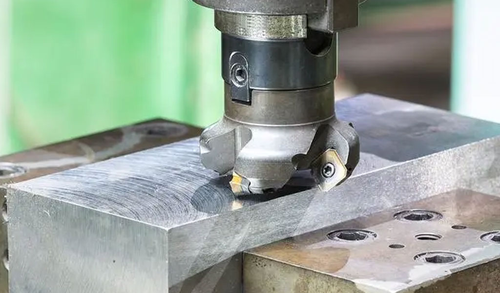
End milling is a machining process where a rotating cutting tool with multiple cutting edges removes material from a workpiece.
Unlike other milling processes, end milling allows for cutting in multiple directions—axial, radial, and tangential—making it suitable for producing intricate shapes, slots, contours, and pockets. The tool used in end milling, called an end mill, typically features a cylindrical shank with cutting edges along its perimeter and end face.
Material Properties of the Workpiece
The properties of the workpiece material significantly influence cutting conditions. Key material attributes include hardness, tensile strength, thermal conductivity, and machinability.
- Hardness and Strength: Harder materials require lower cutting speeds to prevent excessive tool wear, while softer materials can be machined at higher speeds.
- Machinability Rating: Materials with high machinability ratings, such as aluminum and brass, allow for more aggressive cutting parameters compared to difficult-to-machine materials like titanium and Inconel.
- Thermal Conductivity: Materials with low thermal conductivity, such as stainless steel, require cutting conditions that minimize heat generation and avoid thermal damage.
Tool Geometry and Material
The design and composition of the end mill play a pivotal role in determining cutting conditions. Factors to consider include:
- Number of Flutes: End mills typically have 2, 3, 4, or more flutes. Fewer flutes provide better chip evacuation and are suitable for softer materials, while more flutes allow for higher feed rates in harder materials.
- Helix Angle: The helix angle affects chip flow, cutting forces, and surface finish. Higher helix angles improve cutting performance in softer materials, whereas lower angles are better for harder materials.
- Tool Material: High-speed steel (HSS), carbide, and ceramic tools offer different levels of durability and performance. Carbide tools, for instance, are ideal for high-speed machining and harder materials.
- Coatings: Tool coatings like TiN, TiAlN, and DLC reduce friction, improve wear resistance, and enable higher cutting speeds.
Cutting Speed and Spindle Speed
Cutting speed (Vc) refers to the speed at which the cutting edge of the tool moves relative to the workpiece. It is typically measured in meters per minute (m/min) or feet per minute (ft/min). The spindle speed (N) is derived from the cutting speed using the formula:
N=1000×Vc/π×D
Where:
- N: Spindle speed (RPM)
- Vc: Cutting speed (m/min)
- D: Tool diameter (mm)
Optimal cutting speed depends on the material of the tool and workpiece, as well as the cutting conditions. Exceeding the recommended cutting speed can lead to tool wear, while operating below it may reduce efficiency.
Feed Rate Calculation
Feed rate (F) is the linear distance the tool travels per minute and is influenced by the number of flutes, chip load, and spindle speed. It is calculated using the formula:
F=fz×z×N
Where:
- F: Feed rate (mm/min)
- fz: Feed per tooth (mm/tooth)
- z: Number of flutes
- N: Spindle speed (RPM)
Feed per tooth (fz) is the amount of material removed by each cutting edge per revolution and varies based on the tool material, workpiece material, and cutting conditions. An excessively high feed rate may result in poor surface finish or tool breakage, while a low feed rate can lead to unnecessary tool wear.
Depth of Cut
Depth of cut (DOC) refers to the thickness of material removed in one pass of the tool. It is classified into axial depth of cut (Ap) and radial depth of cut (Ae):
- Axial Depth of Cut (Ap): The depth of material removed along the axis of the tool.
- Radial Depth of Cut (Ae): The width of material removed perpendicular to the axis.
The depth of cut should be selected based on the rigidity of the machine, tool geometry, and workpiece material. Excessive depths can overload the tool and machine, leading to chatter or tool failure.
Tool Engagement and Cutting Forces
Tool engagement, or the contact area between the tool and the workpiece, affects cutting forces, heat generation, and tool wear. A higher engagement area increases cutting forces, necessitating adjustments to cutting speed and feed rate.
Coolant and Lubrication
Proper coolant and lubrication are essential for dissipating heat, reducing friction, and flushing away chips. The choice of coolant depends on the workpiece material and machining operation. Common options include:
- Flood Coolant: Provides continuous cooling for high-speed and high-feed machining.
- Mist Coolant: Suitable for light machining operations.
- Dry Machining: Preferred for materials like aluminum, where coolant can cause thermal cracking.
Machine Tool Capability
The capabilities of the CNC machine tool influence the selection of cutting conditions. Considerations include:
- Spindle Power: Limits the cutting speed and feed rate that can be applied.
- Rigidity: A rigid machine minimizes vibrations, allowing for more aggressive cutting parameters.
- Control System: Advanced CNC systems offer features like adaptive control, which optimizes cutting conditions in real time.
Chip Formation and Evacuation
Efficient chip evacuation prevents re-cutting of chips, which can damage the tool and workpiece. Adjusting the cutting parameters and selecting tools with appropriate flute geometries ensures smooth chip flow.
Cutting Condition Optimization
Optimizing cutting conditions involves balancing productivity, tool life, and surface quality. Modern tools such as simulation software and process monitoring systems help refine parameters for specific applications.
Monitoring and Adjustments
Continuous monitoring of the machining process is crucial to maintain optimal conditions. Parameters may need adjustment based on real-time feedback, tool wear, or changes in workpiece material.
Advanced Techniques
- High-Speed Machining (HSM): Involves using high cutting speeds and feed rates with small depths of cut for improved productivity and surface finish.
- Trochoidal Milling: A strategy that minimizes tool engagement and distributes heat evenly, prolonging tool life.
Conclusion
Calculating cutting conditions for end milling requires an in-depth understanding of material properties, tool design, and machining dynamics. By considering all influencing factors and leveraging advanced technologies, manufacturers can achieve efficient, precise, and cost-effective machining.


The Detail Of BE-CU Cnc Machining Shop
BE-CU.COM – As an accomplished CNC machining Service Manufacturer and CNC shop, BE-CU Prototype has been specialized in OEM CNC lathing, custom CNC machining parts production and rapid CNC machining services China for over 35 years and always maintaining the highest standard in delivery speed and reliable quality of precision CNC manufacturing components. With the help of high-level technology and efficient equipment, as well as rigorous attitude, BE-CU passed the ISO9001:2015 quality certification, which supports the long-term development of CNC milling services, CNC turning services, CNC milling-turning, CNC drilling services, 3/4/5 axis machining, gear machining services, CNC machining China custom parts and service, small parts machining, etc.Our CNC machining products can be utilized in a broad range of industries. Contact us for email: [email protected]

-

3-Way Centrifugal Compressor Closed Impeller By 5 Axis Machining
-

3/4/5 Axis Precision Milling Custom Vehicle Parts
-

3D Flexible Welding Platform By Large Machining
-

3D Printed Inconel Exhaust Manifold
-

3D Printing And CNC Machining Custom Black PPS Valve
-

3D Printing Full Transparent Acrylic Lampshade Model
-

4 Axis CNC Machining Titanium Grade 5 Mobile Phone Buttons
-

4 Axis Machining Highly Transparent Acrylic LED Tunnel Light Lens