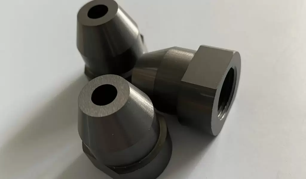
This paper presents a new method called Spindle Peak Frequency (SPF) to determine stable microdrilling parameters. The novelty is that the method does not require a force model, material behavior of the workpiece, modal stiffness and damping of the drilling tool. The only parameter required is the natural frequency of the drill, which is obtained by modal dynamic finite element analysis (FEA). The material constants of the Johnson-Cook material model of Macor ceramics were obtained and implemented into a finite element model of orthogonal cuts to study the cutting mechanism. The results show that the cutting mechanism of Macor is achieved through the initiation and propagation of microcracks.Finally, the developed research method has been used to fabricate a Macor nozzle for a scanning droplet system, in which holes with a diameter of 100 μm and an aspect ratio of 10 were successfully drilled, improving the resolution.
Micro-drilling SPF methodMaterial modeling of MacorDrilling parametersMicro-drilling dynamics Scanning Droplet Systems (SDSs) Scanning Droplet Cells (SDC)
1. Introduction Of Micro-Drilling Macor Ceramic Nozzle
Drilling processes are widely used to drill holes in different structures and materials on both macro and micro scales. Drilling tools can be thought of as rotating, flexible and pre-twisted beams with cutting lips at their free ends where material is sheared off to create holes. Typical requirements for micro- and macro-scale drilling processes are drilling within tight tolerances, avoiding the formation of burrs or chips, depending on whether the material is ductile or brittle, achieving high surface quality and surface integrity, reducing tool wear, and avoiding tool vibration and tool breakage. One of the differences between macro-drilling and micro-drilling is the size of the drilling tool, as reported by Egashira et al., commercial micro-drills with a diameter of 10 μm can be used (2011). In addition, they fabricated micro-drills with a diameter of 3 μm using electrical discharge machining. A reduction in tool diameter results in a reduction in tool stiffness and also affects modal dynamic parameters such as modal mass, damping, and natural frequency. Micro drills can vibrate for smaller depths of cut and lower feed rates than macro drills. Therefore, tool vibration must be avoided by choosing optimal drilling parameters.
Another fundamental difference between macro-drilling and micro-drilling is the mechanics of the cutting process. The micro-scale cutting process is achieved at very small uncut chip thickness (feed rate per tooth), which is close to the cutting tool edge radius. For example, the edge radius of carbide tools can be less than 1 μm, and the edge radius of diamond tools can be less than 100 nm. In addition, mechanical cutting at the micro-scale undergoes both ploughing and shearing cutting regimes. Gouging is observed when the ratio of uncut chip thickness to tool edge radius is insufficient to form chips. The boundary between the gouging and shear cutting phenomena is called the minimum chip thickness. Ploughing is not advisable as it results in burr formation and poor surface quality. Therefore, ploughing must be avoided and cutting parameters must be optimized.Also vollertsen et al(2009) reported that the size effect of micro-cutting increases cutting forces and specific energy due to material strengthening, where cutting is achieved through the grains of the material.
Many researchers put a lot of effort into understanding different aspects of the microdrilling process. One of these aspects is runout, which affects the tolerances of the drilled holes and cutting forces that cause tool breakage. Watanabe et al. (2008) experimentally examined the correlation between drill runout and hole quality using a drill with a diameter of 100 μm at a rotational speed of 5000 s-1. It has been concluded that radial runout is insensitive to drill wear and hole quality because of the centripetal action that occurs in the contact area between the drill and the workpiece under study.
Other aspects of microdrilling include chip morphology, material evacuation, poor burr formation and application lubrication. Zheng et al. (2012) used a micro-drill with a diameter of 100 μm to drill holes in printed circuit boards at spindle speeds up to 300,000 rpm. It has been found that the morphology of chips and hole wall surfaces depends on material properties. Chips are typically conical and helical chips formed from aluminum inlet plates and copper foil, and discontinuous chips formed from fiberglass and softened resin.
In addition, chip morphology and hole quality are affected by feed rate, spindle speed and tool wear. Nan et al. (2011) conducted a series of microdrilling experiments using air lubrication, pure minimum quantity lubrication (MQL) and nanofluidic MQL. For nanofluidic MQL, nanodiamond particles with a diameter of 30 nm have been used with base fluids of paraffin and vegetable oils. For the microdrilling process, uncoated carbide twist drills with a diameter of 200 μm have been used to drill holes in aluminum 6061 workpieces. The experimental results show that the nanofluidic MQL significantly increases the number of boreholes and reduces the borehole torque and thrust. Numerous methods, including analytical, numerical, experimental, and monitoring techniques, have been developed to avoid microdrill braking.
Kudla (2006) studied the strength of high-speed steel and tungsten carbide micro-drills under bending, torsion and complex loading conditions. Kim et al. (2009) using the pecking method and monitoring the thrust signal. Through the time domain and frequency domain analysis of the thrust, the pecking monitoring parameters are introduced to avoid tool breakage and prolong tool life. Yang et al. (2008) developed an online monitoring system for microdrills using fuzzy neural network rules. The neural network has been trained with sampled data obtained in real time from the three-phase current of the spindle motor. The experimental results show that for a properly defined threshold, micro-drill breakage can be prevented. Zdebski (2012) simulated micro-cutting tool fracture by predicting maximum stress and tool failure with reference to fracture stress. This method has determined the maximum force that can be applied to different microtool designs.
Chatter phenomenon plays an important role in the performance of the cutting process. The presence of chatter in drilling increases tool wear rates, reduces surface quality, affects the surface integrity of machined parts and increases cutting forces, which can lead to tool breakage, especially at the microscopic scale. Chatter in macro drilling has been the subject of research for decades, and researchers have developed comprehensive mathematical models and experimental procedures. Altintas and Weck (2004) summarize flutter models developed in macroscopic drilling, including torsional-axial flutter stability, lateral flutter stability, lateral rotational vibration, and deep hole drilling dynamics. In addition, they report some challenges in modeling flutter phenomena in macroscopic drilling, including difficulties in modeling drilling forces due to the effect of chisels, while simultaneously accounting for lateral, torsional, and axial vibrations while drilling, considering Mathematical models with finer drilling depths make it difficult to predict rotational vibrations in deep hole drilling.
At the microscopic scale, flutter models are mainly used for micromilling. Afazov et al. (2012) developed and validated a new micro-milling chatter model by considering process nonlinearities. Since modeling the cutting forces of microdrills and obtaining the dynamics of microdrilling is a challenge, a chatter model for microdrilling has not been developed. The receive coupling technique has been used to obtain the modal dynamic parameters of the micro end mill tip. Regarding microdrills, Zhang and Babitsky (2011) proposed frequency finite element analysis, and the solid elements used to model microdrills are called solid models, and are modeled by combining beam elements representing tool shanks and solid elements representing grooves. as a mixed model. Imran et al. (2008) carried out an experimental study of micropore drilling with a diameter of 500 μm in single crystal nickel-based superalloy (CMSX4). The results show that the spindle speed has a great influence on the number of holes drilled. After studying spindle speeds of 1000-11,000 rpm at a constant feed rate per tooth, the highest number of holes was obtained at a spindle speed of 3000 rpm. However, the authors do not explain the effect of spindle speed on the number of holes drilled. The results may be related to the chatter effect, and at 3000 rpm the drilling process was more stable and the tool wear rate, thrust and torque were lower.
Most microdrilling research is done on metals. In addition to the microdrilling process aspect, the workpiece material and its behavior are also an important aspect. Glass ceramic materials are widely used in different applications. An example of a glass ceramic material is Macor. According to Plastic International (2012), Macor can withstand temperatures up to 1000 °C. It is an excellent insulator at high voltages, various frequencies and high temperatures. When it’s baked properly, it won’t degas in a vacuum. Macor materials can be used in a variety of applications including: (i) insulator or coil holders and vacuum feed troughs; (ii) baffles, headers and windows for microwave tube assemblies and as sample holders in field ion microscopes; ( iii) Spaceborne gamma radiation detectors; (iv) Welding equipment for oxyacetylene torch tip nozzles; (v) Medical equipment. Davis et al. (1998) reported that Macor materials have been drilled at high penetration rates at the macroscale.
Most drilling studies at the macro- and micro-scales are performed on ductile metals. Glass-ceramic Macor materials have been studied to some extent at the macro scale, but not yet at the micro scale. One of the main goals was to develop a new method to determine stable microdrilling parameters. Another goal was to obtain, for the first time, material constants for an isotropic thermo-elasto-plastic material model with a strain rate dependent viscoplastic material model in order to study cutting mechanisms in Macor cutting using FEA. The motivation was to apply the research method to the nozzle application of a scanning droplet system, where a 100 μm hole with an aspect ratio of 10 is required.
Methodology: Figure 1 shows an overview of the methods used in the current study. First, the microdrill was examined with a scanning electron microscope (SEM) and geometric features were measured. The measured edge radius was used to model the cutting tool for the finite element model of orthogonal cutting. The material constants for the isotropic thermo-elastoplastic material model with the strain rate dependent viscoplastic material model were obtained and implemented into the orthogonally cut finite element model. A finite element model of orthogonal cutting is used to predict the mechanism of the cutting process.
It must be mentioned that finite element models of orthogonal cutting have been used to predict cutting forces in micro-turning and micro-milling. In micro-hole machining, the finite element model of orthogonal cutting can only consider the cutting force at the cutting edge, but cannot consider the effect of the high aspect ratio lower chisel lip and friction. A new method called Stable Peak Frequency (SPF) is proposed, which identifies stable micro-drilling parameters (feedrate and spindle speed). The method requires as input the natural frequency of the micro-drill vibration. The natural frequencies were obtained by modal dynamic FEA with the same tool geometry as the micro-drill used for experimental validation and production. Finally, the nozzle of the scanning droplet system was fabricated by drilling holes with a diameter of 100 μm and an aspect ratio of 10.
2.Material Model For Macor Cutting Operations
Constitutive material models commonly used in cutting operations describe flow stress as a function of plastic strain, strain rate, temperature, and other mechanical properties such as hardness, dislocations, microstructure, etc. The Johnson-Cook (JC) constitutive material model is one of the most widely used material models for cutting operations (Johnson and Cook, 1983). The JC model is an isotropic thermo-elasto-plastic with strain rate and temperature dependent viscoplasticity (see equation (1))
where T is the reference temperature, Tr is the transformation or room temperature, Tmelt is the melting temperature, A is the initial yield stress, B is the hardening modulus, n is the hardening exponent, C is the strain rate correlation coefficient, and m is the thermal softening coefficient.
The JC material model has been widely used to model cutting forces, chip formation, and residual stresses using 2D and 3D finite element models, as described by Ulutan and Ozel (2011). Furthermore, Jin and Altintas (2011) used the JC material model to predict cutting forces for orthogonal cutting at the microscale using slip-line theory. The JC material model can also be used in a variety of applications where strain rate is an important factor.
The JC model is primarily used for machining materials with high strains and strain rates. Due to its empirical nature, the model can also be used to describe the relationship between stress, strain and strain rate at low strains. The main purpose of this section is to obtain the material constants for the equations. (1) For Macor, experimental tests under different loading conditions, strain rates and temperatures are required. Chen (1995) used a modified split Hopkinson (Kolsky) pressure bar test on Macor under various loading conditions and strain rates up to 3600 s-1. It has been observed that substantial propagation and interaction of microcracks is thought to occur, as indicated by the very low values of the tangential modulus near failure.
Inelastic deformation was also observed in uniaxial testing experiments on the Macor. In all experiments to obtain breaking strength, the specimens were split axially. It is observed that the fragment size decreases with increasing strain rate, indicating that the number of simultaneously propagating cracks increases with increasing strain rate. In addition, the average value of the measured pre-failure poison ratio was 0.21. The Poisson’s ratio remains relatively constant until very close to failure when microcrack nucleation and growth occurs. Microcracks mainly appear at the interface between the glassy phase and the crystalline phase and at the triple grain boundary junction. In addition, the microcracks appear to be randomly oriented in the plane of the micrograph and are uniformly distributed.
The experimental data obtained by Chen (1995) were used to obtain the material constants for the JC model. It is also worth mentioning that no other recent experimental tests were found in the literature to consider the effect of inelastic strain and strain rate on Macor’s yield stress. Temperature effects are not considered in the current model because Macor materials tend to fail at small strains. This does not cause a lot of heat due to low plastic deformation. The main source of heat will be generated at high cutting speeds due to friction between the cutting tool and the Macor workpiece. The material constants are obtained in the following order. First, Macor’s constants A, B, and n are obtained at a strain rate of 280 s-1 using the equation. (2). The experimental data and fitting curve are shown in Fig.2. Next, the experimentally obtained ultimate stress (σu) for different strain rates includes the effect of strain rate on yield stress. The ratio between the ultimate stress and the reference ultimate stress is plotted against the ratio between the strain rate and the reference strain rate.
The reference point was chosen for the strain rate of 280 s-1 to more accurately describe the Macor behavior at high strain rates, which is the case for cutting operations including microdrilling. The equation is then fitted to the experimental data using (3) to obtain the constant C, as shown in Figure 3. (1) Given in Table 1. Figure 4 shows the Macor behavior using equations. (1) and the material constants in Table 1. The JC material model (equation (1)) is able to describe the Macor inelastic nonlinearity. Typically, glass-ceramic materials are characterized by failure at strains of 0.01-0.02. For Macor, failure at a strain rate of 280 s-1 occurred at a strain of 0.01 (Chen, 1995). In addition, Frew et al. (2002) reported that Macor failed at a strain of 0.01 for strain rates of 130 s-1 and 165 s-1. Based on the data available in the literature, it can be assumed that failure occurs at a failure strain (ɛf) of 0.01. The cumulative damage law given by the equation. (4) is used to predict fracture, where Δɛ is the increment in effective plastic strain. Suppose failure occurs when D = 1. The presented material model is implemented in the orthogonal cutting finite element model described in Section 5.2.
3.Stable Peak Frequency (SPF) Method
A stable microdrill means that the tool has no self-excited vibrations (chatter). Chatter can be avoided by determining the stability flap for a specific material and cutting tool. Stable lobes can be obtained experimentally or using mathematical models. As mentioned in Section 1, a flutter model for microdrills has not been developed because it remains a challenge to develop a reliable force model and obtain the dynamics of micro-drills. Furthermore, experimental determination of stable lobes is not feasible due to low efficiency and high cost. Typically, experimental methods are used to validate flutter models. Furthermore, measuring reliable signals (cutting force, acoustic emission and displacement) for microtool chatter is a challenging task due to the large amount of noise. Therefore, new methods are sought in which engineers and practitioners can select stable cutting parameters in microscale cutting operations, including microdrilling, from the first time.
This paper proposes a new method called Stable Peak Frequency (SPF). The method aims to determine stable microdrilling cutting parameters for various tools by avoiding chatter. The SPF method involves determining the feed rate and spindle speed in microdrilling.
The method does not require a force model, material behavior of the workpiece, modal stiffness and damping of the cutting tool. The only required parameter is the natural frequency of the tool vibration. First, the feed rate per tooth/groove is determined based on the minimum chip thickness, which depends on the edge radius (r) of the tool. The minimum chip thickness varies between 0.1r and 0.5r for different materials and cutting conditions. In the SPF method, it is recommended that the feed rate per tooth be within the interval. Lower or higher feed rates can also be used in the proposed process. A feed rate per tooth lower than the edge radius results in furrowing, which is caused by poor surface finish and burr formation. For example, a feed rate below the minimum chip thickness results in a drilling process in the planing state. In addition, low feed rates increase tool wear because more revolutions are required to drill a volume of material where the cutting edge is in contact with the workpiece material more frequently. High feed rates per tooth can cause unstable drilling due to chatter, which can lead to tool breakage.
The core step of the SPF method is to determine the spindle speed of the corresponding micro-drill. It is known that at certain spindle speeds, the cutting process is more stable, enabling higher depths of cut. The SPF method is designed to determine the spindle speed at which the highest depth of cut can be achieved. Since there is no micro-drilling flutter model, the micro-milling model developed by Afazov et al. (2012) for identifying periodicity in spindle speed due to high depth of cut. The results of sensitivity analysis for different materials (AISI 4340, AISI H13 and Ti6Al4V), different values of tool geometry parameters (rake angle and edge radius), modal dynamic parameters (natural frequency, damping ratio and stiffness) flute tool showed that, There is a correlation between the natural frequency and the main axis frequency obtained in the middle of the lobe (see Figure 5). The relationship can be given by:
where f (Hz) is the spindle frequency in the middle of the stable lobe, fn (Hz) is the natural frequency of tool vibration, and i is the number of lobes. Figure 5 shows the stability lobe of a two-edged end mill cutting a steel workpiece. It can be seen that the first 3 spindle frequencies located in the middle of blades 1, 2 and 3 (f1, f2 and f3) result in a higher depth of cut. Furthermore, it can be seen that for a larger stable frequency range of the first three lobes, a higher depth of cut can be achieved. Therefore, it is recommended to select the principal axis frequency of the first three lobes.
Figure 5. Stability lobes obtained for an end mill with a natural frequency of 4035 Hz and a feed rate of 4 μm/tooth (Afazov et al., 2012).
The natural frequency of cutting tool vibration, also known as chatter frequency, can be obtained experimentally by selecting cutting conditions that cause forced vibration of the tool and measuring different signals such as cutting force, vibration, and acoustic emission. The signal obtained in the time domain is transformed into the frequency domain using a Fast Fourier Transform (FFT), where the flutter frequencies can be identified. The main error to consider when obtaining the flutter frequency is the large amount of noise in the microscale measurement process.
In addition, the sensitivity of the sensor and the sampling capability of the signal acquisition device can lead to additional errors. The experimental procedure is expensive and time-consuming, therefore, the finite element method was chosen to obtain the flutter frequency. Errors due to differences between modeling tool CAD geometry and actual tool geometry, poor mesh quality, and uncertain material properties are minimized.
4.Numerical Model
In this section, the modal dynamic finite element analysis of the micro-drill and the finite element model of the orthogonal cutting are presented.
a.Modal Dynamic Finite Element Analysis
Determining the dynamic behavior of micro-drills is an important factor in selecting stable cutting parameters. Typically, the dynamics of macro-drills are obtained by exciting the bit with an impact hammer and measuring the displacement of the tool tip with an accelerometer. Coupling force and displacement signals to obtain a frequency response function. The modal dynamic parameters (modal damping, modal natural frequency, modal stiffness and modal mass) are then obtained by using fitting techniques. This method cannot be directly applied to micro-drills because the accelerometer cannot be attached to the tool tip. FEA emerged as an alternative solution to obtain the dynamics of micro-tools, where the complex geometry of micro-drills can be considered. Therefore, FEA is used in this paper to obtain the dynamics of a micro-drill with a diameter of 100 μm.
First, the CAD geometry and mesh were modeled to represent an actual micro-drill with a diameter of 100 μm and a slot length of 1.3 mm. The actual micro-drill was measured by SEM and the FE mesh was generated accordingly (see Figure 6). The micro-drill is meshed with quadratic tetrahedral elements with reduced integration. It is assumed that the thin coating layer does not affect the tool dynamics, and the micro-drill is modeled as a carbide material with an elastic modulus of 580 GPa, a Poisson’s ratio of 0.28, and a density of 14,300 kg/m3. Zero displacement is applied to shank nodes that are in contact with the collet. Dynamic FEA is performed in two steps. In the first step, a frequency analysis is performed using the Lanczos eigensolver to obtain mode shapes for frequencies in the 0-10 KHz range. The modal analysis is performed in step 2 by considering the predicted modal shapes from the frequency analysis. During the modal analysis step, concentrated forces are applied to the two tool tips to represent torque. Furthermore, a concentrated force is applied in the axial direction. Damping is not considered in the modal dynamic analysis because the main purpose is to obtain the natural frequencies of the micro-drill vibration.
b.Finite Element Model Of Orthogonal Cutting
Finite element models of orthogonal cutting have been widely used to predict cutting forces, chip formation and residual stresses in various cutting operations. For example, predicted cutting forces for orthogonal cutting may be relevant for turning, broaching, and milling operations at the micro and macro scales. In drilling, orthogonal cutting can only represent the cutting mechanism at the cutting edge. It also predicts the cutting forces acting on the cutting edge, but not the effects of chisel lip, friction, and evacuation of removed material. Finite element modeling of orthogonal cuts can be used to describe the Macor’s cutting mechanism, where some engineering decisions can be made.
Orthogonal cuts of Macor were simulated in dynamic thermomechanical FEA using the explicit integration model developed by Afazov et al. (2010). In the FE model, the geometry of the tool is created from scanning electron microscope measurements. For 2 double-edged TiN-coated micro-drills with a diameter of 100 μm, the edge radius measured using SEM was approximately 0.8 μm (see Figure 7). A slip-stick friction model is used between the tool and the workpiece. It should be mentioned that friction causes nonlinearity of cutting forces due to variations in contact pressure. For example, edge radii create higher contact pressures, while friction causes adhesion-dominant behavior. A coefficient of friction of 0.1 was chosen based on experimental studies conducted by McKellop et al. (1981). Research reports that Macor has a low coefficient of friction. The material model described in Section 3 is implemented in the FE model. The finite element model is meshed with linear quadrilateral elements with reduced integration and the size of the contact area is about 5 nm. Once the damage criteria are met, these elements are deactivated from the stiffness matrix. Table 2 presents the Macor mechanical and physical properties used in the orthogonal cutting finite element model.
5.Results And Discussion
The results of the SPF method and Macor’s cleavage mechanism are first introduced and discussed. The fabrication strategy for punching is then addressed, and finally, punching is performed for the nozzle head of the Uniscan M370 Scanning Droplet System (Uniscan Instruments, 2012).
The natural frequencies of the micro-drill are first obtained from the modal dynamic FEA in Section 5.1. The total time used in the modal dynamic finite element analysis was 0.11 s with a time increment of 1 × 10⁻⁴ s. The displacement magnitude at the center node at the bottom of the microdrill was obtained from the model and converted to the frequency domain using FFT. Figure 8 shows that the micro-drill exhibited the highest vibration at a frequency of 1973 Hz. Furthermore, a sensitivity analysis was performed by applying torque and axial loads only to the micro-drill. These analyses also confirmed that the highest FFT shift magnitude again resulted in a frequency of 1973 Hz. Also, running more analyses with different magnitudes of torque and axial load, again the highest FFT displacement magnitude results in a frequency of 1973 Hz. Therefore, a natural/flutter frequency of 1973 Hz is used in the equation. (5) Define the main axis frequency in the middle of the microdrill stabilizing flap. In this study, the calculated spindle frequency in the middle of leaf 2 at a spindle speed of 337.8 Hz or 20,260 rpm was used to validate the SPF method.
After examining multiple micro-drills from the same supplier using SEM, two micro-drills were selected for experimental drilling trials. Two micro-drills with an edge radius of 0.8 ± 0.03 μm were selected for validation of the SPF method. The experimental trajectory was carried out on a KERN EVO machining center with a positioning accuracy of 1 μm. Use dry drilling conditions without fluids to expel the removed material. Both micro-drills use a feed rate of 1.2 μm/slot. A spindle speed of 20,260 rpm, calculated by the SPF method, was used for the first micro-drill trial with a feed rate of 48.6 mm/min. The spindle speed was 25,550 rpm and the feed rate was 61.3 mm/min for the trajectory of the second microdrill. The runout of both micro-drills was measured and controlled to less than 0.5 microns prior to drilling trials. Step-by-step the trajectory by increasing the hole depth by 25 µm per trial. It was observed that the microdrills of the first and second microdrills were broken at 300 μm and 225 μm hole depths, respectively. This shows that the drilling parameters defined by the SPF method result in a 27% higher aspect ratio. The location of breakage for both tools was observed to be at the level of the workpiece surface. Table 3 shows the predicted natural frequencies for five different lengths of FE while keeping the helical pitch the same. The results show that as the groove length increases, the natural frequency decreases. This means that microdrills with longer flutes must use lower spindle speeds. For example, the spindle speed in the middle of the first stabilization lobe of a 2.3 mm blade length micro-drill is 5875 rpm.
The cutting speed is 106 mm/s, representing the cutting speed of the micro-drill tip, the spindle speed is 20,260 rpm, the diameter is 100 μm, and the cutting tool applied to the orthogonal cutting finite element model. The simulated uncut chip thickness is 1.2 μm, while the edge radius is 0.8 μm. Figure 9 shows the temperature field of the tool after contact with the Macor workpiece. It can be seen that the microcracks propagate and the cutting temperature is 37°. This indicates that the Macor material is removed in the particles due to the generation and propagation of microcracks. These results indicate that microcracks may appear on the drilled surface of the hole, which is undesirable due to reduced fatigue life. Therefore, the drilled holes in the experimental tests have been examined with SEM, and no microcracks were observed on the surface of the drilled holes. This can be explained with Figure 9, where microcracks appear on the rake face.
Based on the experiments and modeling analysis performed, the microdrilling parameters determined using the SPF method (spindle speed 20,260 rpm, feed rate 48.6 mm/min) were used to machine 1 mm deep holes. Drilling is done step-by-step on the KERN EVO machining center. Drilling is done in 10 steps, with each step reaching a depth of 100 microns. In addition, drilling is carried out with an air flush to expel the removed particles from the holes.
The step-by-step drilling strategy of the Macor substrate is used to fabricate fine-tip nozzles for scanning probe instruments, including the Scanning Electrochemical Workstation M370 module known as the Scanning Droplet System (SDS) or Scanning Droplet Cell (SDC). The SDS system confines a liquid microcell in contact with the sample surface to measure electrochemical (EChem) and corrosion reactions in the confined space area where the droplet contacts the sample. By confining electrochemistry to a small region, surface EChem properties can be studied in the same region by potentiostatic or galvanostatic control. Repeating this process on an XY raster scan of the surface builds an image of the surface’s EChem properties.
Often, general areas of interest such as surface coatings (defects/uniformity) and corrosion and inhibition are the goals of SDS. and a general desire to improve resolving power; there is an interest in increasing the resolution so that individual metal grains/grain boundaries can be studied. While this can be achieved by pulling capillaries, they are fragile and require a thermal or laser pipette to pull the device; finding an alternative that is robust, easy to use, reusable, and relatively inexpensive is an ideal goal.
The performance of SDS in terms of resolution is directly related to the droplet size in contact with the sample, which in turn is directly related to the nozzle size. The research conducted in this paper managed to achieve a smaller fine-tip nozzle size. The original SDS nozzles were made of PTFE, thus obtaining high chemical resistance from a relatively easy-to-process material. While this construction easily allows solutions to flow in and out of the SDS head, the material of choice here is glass because not only do we need its inert and insulating properties, broad chemical resistance, but we also need a wider temperature range and its robustness Structure.
Fabrication of a fine-tip SDS nozzle with a total tip diameter of 192 μm significantly improved resolution capabilities, with a tip diameter more than 5 times smaller (surface area reduced by a factor of more than 25), as well as enhanced imaging capabilities. Figure 10 shows the SEM images of the original SDS head, the new Macor fine tip nozzle and the 100 μm orifice.
In Conclusion
This paper presents a new method called Spindle Peak Frequency (SPF) to determine microdrilling parameters to achieve high borehole aspect ratios. The results show that the SPF method can achieve higher hole aspect ratios for micro-drills with a diameter of 100 μm.
Material constants for an isotropic thermo-elasto-plastic material model with strain rate dependent viscoplastic material model have been obtained and applied to a finite element model of orthogonal cutting. The results show that the cutting mechanism of Macor is achieved through the initiation and propagation of microcracks.
Holes with a diameter of 100 μm and an aspect ratio of 10 have been successfully fabricated on the Macor nozzle of the scanning droplet system, which improves the lateral resolution of the scanning droplet system by a factor of about 5.
More validation of the SPF method for different materials and cutting operations, including turning and milling, is the subject of future research.
This article ends here, if you have any questions, please call the Pintejin EMAIL:[email protected]
About China Advanced Ceramic CNC Machining Company – Be-Cu
Manufacturer of precision machined components. Ceramic cnc machining components include high dielectric strength, electrical & corrosion resistance, & non-porous & non-shrinking properties.Manufacturer of high temperature fabricated and machinable ceramics including alumina, glass-ceramic, alumino-silicate, boron nitride and zirconium phosphate. Adhesives, coatings and potting compounds to 3200 degrees F,Air firing services for ceramics up to 1650 degrees C also available. Products include insulators, guides, washers, tubes, blocks, & rods for thermal, electrical, corrosion exposure, structural, wear, & semi-conductor operations. Services include machining to tolerances of +/- .0001, ultrasonic core drilling, centerless grinding, milling, & ID & OD threading.Surface grinding, dicing, OD (outer dia.) grinding, ID (inner dia.) grinding, centerless grinding, hole drilling, jig grinding, lapping, honing & polishing service are also available. Diamond grinding with dimensional tolerances of 5 microns & surface finishes of 0.2 microns (8 micro-in.) can be performed.Blanket orders and AutoCAD files & other 3d files accepted.Contact us for your machining ceramic project!
-
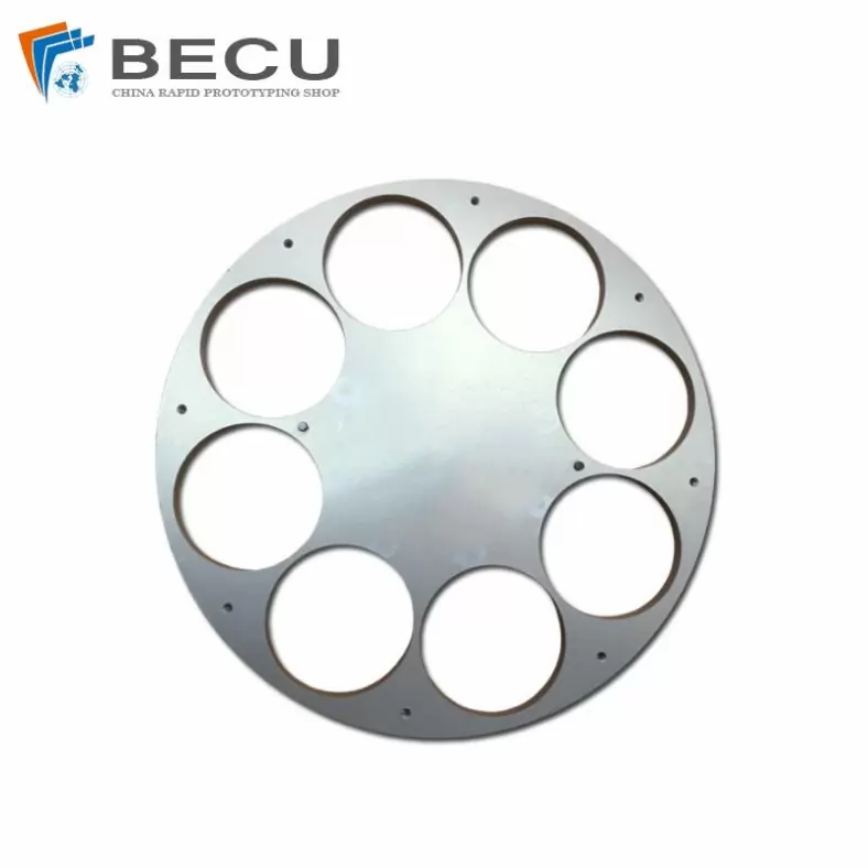
Metal Plating ZrO2 Zirconia Ceramic Parts
-
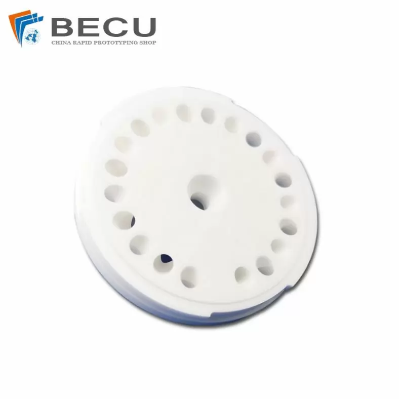
ZrO2 Structural Ceramic Semiconductor Parts
-
Alumina Ceramic Screw Type Parts
-
Cnc Machining Alumina Ceramic Screw Heating Pipe
-
Brushed Fishing Tackle Alumina Ceramic Accessories
-
Winding Machine Alumina Ceramic Wire Wheel
-
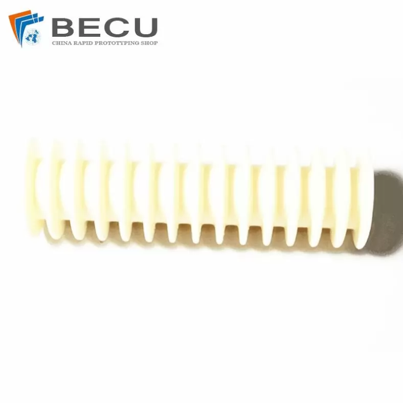
Insulation Device Microcrystalline Ceramic Multi-Slot Ceramic Column
-
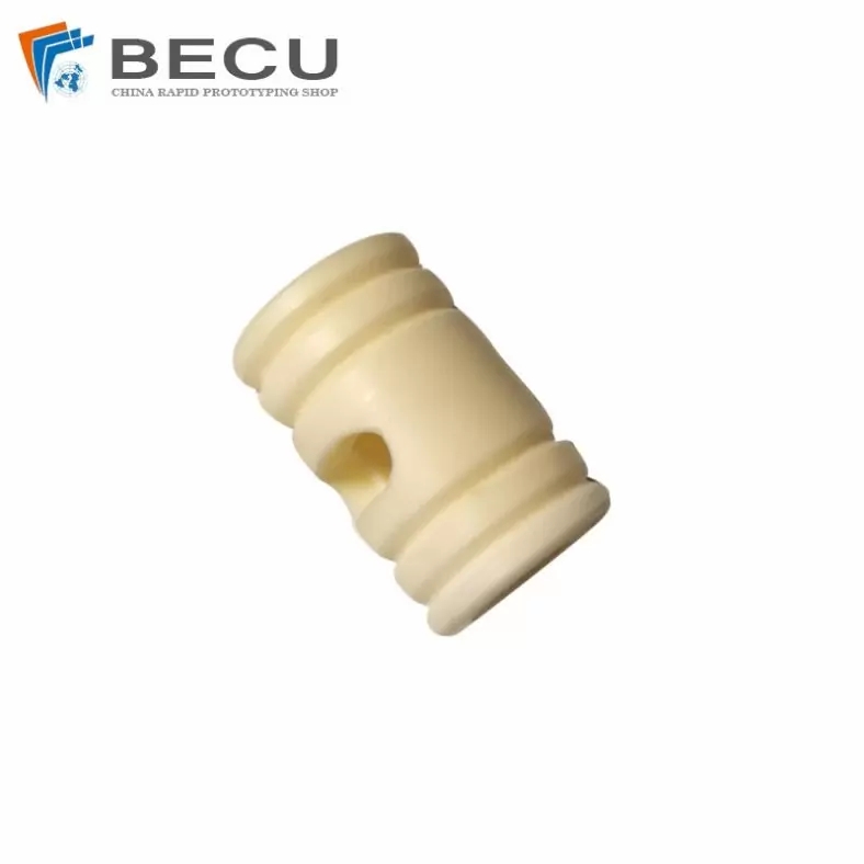
99 Alumina Ceramic Spool Insulator Sleeve
-
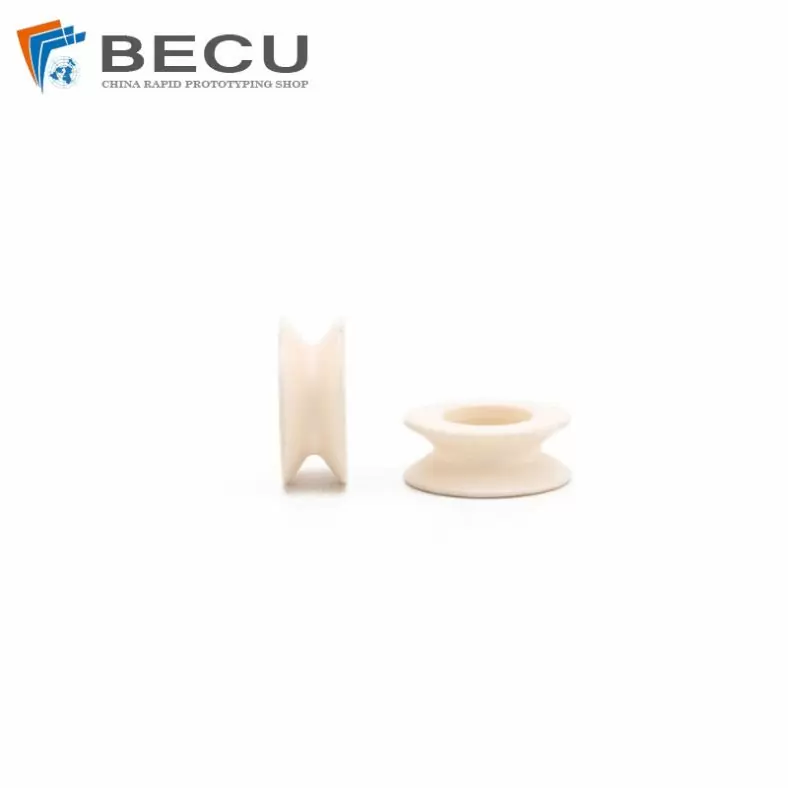
The Alumina Ceramic Ring Of Textile Machine Thread Passing Wheel
-
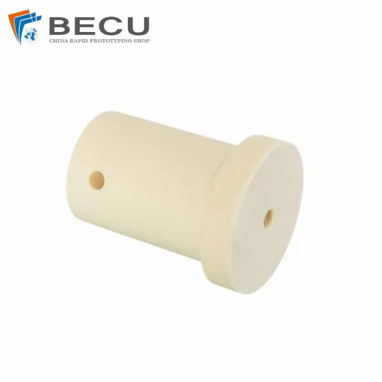
Isostatic Pressure Insulation Alumina Ceramic Column
