
According to the structural characteristics of the shell, the die-casting process is designed. Through the numerical simulation of the two gating systems using ProCAST software, the locations and causes of shrinkage cavities and porosity were analyzed, and a better gating system was selected to optimize the die-casting process through comparison. The results show that after process optimization, the castings have no shrinkage holes or porosity defects, and have been verified by production, which meets the technical requirements
Shell body die casting is a sophisticated manufacturing process that involves the production of complex metal components through the use of molds and high-pressure injection. This method is widely utilized in various industries, including automotive, aerospace, and consumer goods, due to its ability to create precise and intricate designs with excellent surface finishes. This article explores the design and implementation of shell body die casting, including the underlying principles, materials used, design considerations, and applications.
Die casting is a kind of casting technology m with a high degree of automation and capable of mass production of parts with complex shapes. The castings produced by it have the advantages of good compactness, high precision, less machining allowance, and excellent mechanical properties. It is used in automobiles and machinery.
We has been widely used in equipment and other fields. The casing shell is an important carrier for the installation of auto parts. Its wall thickness is relatively thin, but its mechanical properties, precision, and air tightness are required to be high, and mass production is required. Therefore, pressure casting is the best shell for manufacturing. s Choice.
This paper analyzes the structure of the casting, designs the casting system of the casting, and simulates it with PmCAST software. Through the analysis of the simulation results, the process is optimized to eliminate the defects such as shrinkage and porosity, so as to obtain A die-casting process that meets the technical requirements of the shell.
1. Overview of Die Casting
Die casting is a metal casting process characterized by the use of a mold, or “die,” into which molten metal is injected at high pressure. The die casting process is divided into two main categories: hot chamber die casting and cold chamber die casting. In hot chamber die casting, the melting pot is part of the machine, allowing for continuous feeding of molten metal. In contrast, cold chamber die casting involves pouring molten metal into a separate chamber before injection.
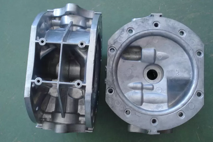
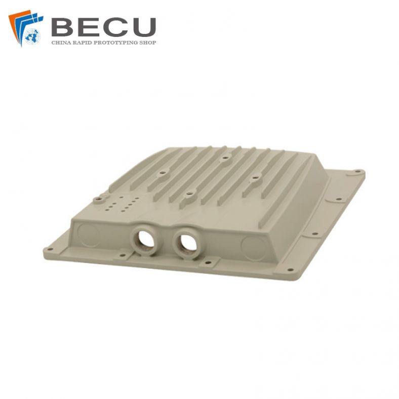
The casting under study is a casing for auto parts produced by a certain company. Its three-dimensional modeling diagram is shown in Figure I. The dark area is the machining surface of the casting, the machining allowance is 0.5 mm, and the outline size of the casting It is 103 mm x 98 mm x 89 mm, the casting volume is 234 108 mn r’, the mass is 632 g, the thickest wall is 5.5 mm, the thinnest wall is 2.5 mm, and the average wall thickness is 3 mm. The casting material is Al-Si-Cu alloy YL113 with good fluidity, good air tightness, and high wear resistance. Its alloy composition is shown in Table lw. Castings are required to have a smooth surface, the draft angle should not exceed 1.5°, the casting shrinkage rate is 0.6%, and there should be no internal defects such as shrinkage holes and porosity.
1.1 Advantages of Die Casting
The die casting process offers several advantages, including:
- High Precision: Die casting can produce components with tight tolerances and intricate geometries.
- Surface Finish: Components typically have a smooth surface finish, reducing the need for extensive machining.
- Material Efficiency: Minimal waste is generated, as the process allows for near-net-shape production.
- Speed: High production rates are achievable, making die casting suitable for large-volume runs.
1.2 Disadvantages of Die Casting
Despite its advantages, die casting also has limitations:
- Initial Tooling Costs: The cost of designing and manufacturing die casting molds can be high.
- Material Restrictions: Not all metals are suitable for die casting; the process is typically limited to non-ferrous alloys such as aluminum, zinc, and magnesium.
- Porosity: Components may exhibit porosity, which can affect mechanical properties and performance.
2. The Shell Body Die Casting Process
Shell body die casting is a specific type of die casting that employs a shell mold, typically made from a combination of metal and sand. This process is particularly advantageous for producing thin-walled components with complex shapes.
2.1 Process Steps
The shell body die casting process can be broken down into several key steps:
- Mold Preparation: The shell mold is created by applying a mixture of sand and resin to a heated metal pattern. The heat causes the resin to harden, forming a rigid shell around the pattern.
- Shell Removal: Once the shell has cured, it is removed from the pattern. This creates a hollow shell mold that will be used for casting.
- Assembly: The two halves of the shell mold are assembled and clamped together in a die casting machine.
- Metal Melting: The metal alloy is melted in a furnace, reaching the necessary pouring temperature.
- Injection: The molten metal is injected into the shell mold at high pressure, filling the cavity.
- Cooling: The metal cools and solidifies within the mold.
- Demolding: After cooling, the mold is opened, and the cast component is removed.
- Finishing: The cast part may undergo additional finishing processes, such as machining, coating, or surface treatment.
2.2 Material Selection
The choice of material for shell body die casting is critical and is influenced by factors such as mechanical properties, corrosion resistance, and thermal conductivity. Common materials used include:
- Aluminum Alloys: Known for their lightweight and excellent corrosion resistance, aluminum alloys are frequently used in automotive and aerospace applications.
- Zinc Alloys: These alloys are characterized by high fluidity and can produce intricate details with good surface finishes.
- Magnesium Alloys: Offering a high strength-to-weight ratio, magnesium alloys are often selected for applications where weight reduction is crucial.
3. Design Considerations
When designing a shell body die casting process, several factors must be considered to ensure optimal performance and efficiency.
3.1 Part Design
The geometry of the part plays a significant role in the success of the die casting process. Considerations include:
- Wall Thickness: Uniform wall thickness is essential to avoid defects such as warping and cracking. Designers should aim for a thickness that balances strength and manufacturability.
- Draft Angles: A slight draft angle (usually 1-3 degrees) is necessary to facilitate the removal of the part from the mold without damaging the surface.
- Radii and Fillets: Incorporating fillets and radii can enhance the flow of molten metal and reduce stress concentrations.
3.2 Mold Design
The mold itself must be designed to withstand high pressures and temperatures while providing an accurate representation of the part. Key considerations include:
- Material Selection: Molds are typically made from high-strength steels or aluminum alloys to withstand the casting process.
- Cooling Channels: Proper cooling channel design is essential for controlling the cooling rate of the metal and ensuring uniform solidification.
- Ejector Systems: Ejector pins or plates may be incorporated into the mold design to assist in part removal.
3.3 Process Parameters
Optimizing process parameters is crucial for achieving high-quality castings. Parameters include:
- Injection Speed: The speed at which the molten metal is injected into the mold can affect filling patterns and surface quality.
- Die Temperature: Maintaining an appropriate die temperature is essential for ensuring proper flow and solidification of the metal.
- Pressure Control: Controlling the injection pressure helps prevent defects such as porosity and incomplete filling.
4. Quality Control in Shell Body Die Casting
Quality control is a vital aspect of the shell body die casting process, ensuring that components meet the required specifications and performance standards.
4.1 Inspection Techniques
Several inspection techniques can be employed to assess the quality of die cast components:
- Visual Inspection: Basic visual checks can identify surface defects such as cracks, pits, or excessive flash.
- Dimensional Measurement: Precision measuring tools, such as calipers and gauges, are used to verify that the part dimensions fall within specified tolerances.
- Non-Destructive Testing (NDT): Techniques such as ultrasonic testing and X-ray inspection can detect internal defects without damaging the part.
4.2 Testing Standards
Compliance with industry standards and testing protocols is essential for ensuring quality and reliability. Common standards include:
- ASTM: The American Society for Testing and Materials provides guidelines for testing various materials and components.
- ISO: The International Organization for Standardization establishes international standards for quality management and assurance.
5. Applications of Shell Body Die Casting
Shell body die casting is employed in a diverse range of applications across multiple industries.
5.1 Automotive Industry
The automotive industry utilizes shell body die casting for components such as engine blocks, transmission housings, and structural parts. The lightweight and durable nature of aluminum and magnesium alloys makes them ideal for enhancing fuel efficiency and performance.
5.2 Aerospace Industry
In the aerospace sector, die casting is used for producing components that require high strength-to-weight ratios and excellent corrosion resistance. Applications include aircraft frames, brackets, and housings for critical systems.
5.3 Consumer Goods
Consumer products, including appliances, electronic enclosures, and decorative items, often leverage shell body die casting to achieve complex designs and attractive finishes.
5.4 Medical Devices
The medical industry benefits from die casting by producing components for surgical instruments, diagnostic equipment, and housing for medical devices. The precision and reliability of die-cast parts are crucial in this sector.
6. Future Trends in Shell Body Die Casting
The field of shell body die casting is continually evolving, driven by advancements in technology, materials science, and industry demands.
6.1 Automation and Robotics
The integration of automation and robotics in the die casting process is expected to enhance production efficiency and consistency. Automated systems can optimize process parameters in real-time, reducing variability and improving quality.
6.2 Advanced Materials
Research into new alloys and composite materials is underway, aiming to improve the mechanical properties and performance of die-cast components. These advancements may lead to lighter, stronger, and more durable products.
6.3 Sustainability Initiatives
As industries increasingly prioritize sustainability, shell body die casting processes are adapting to reduce energy consumption and material waste. The use of recycled materials and environmentally friendly practices is likely to become more prevalent.
Conclusion
Shell body die casting is a vital manufacturing process that enables the production of complex, high-quality components across various industries. By understanding the principles of die casting, including material selection, design considerations, and quality control, manufacturers can harness the advantages of this process to meet the evolving demands of the market. As technology continues to advance, the future of shell body die casting holds promise for greater efficiency, innovation, and sustainability.
In the mold design, the die casting process is the most important, which directly affects the quality of the casting, the production and Cnc machining cost, and the difficulty of mold manufacturing. The die casting process includes the selection of parting surface, the design of the gating system, the design of the overflow and exhaust system
- The shape of the casing is relatively complicated, and a core pulling mechanism is required. Therefore, it is difficult to manufacture the mold. Therefore, the casting adopts a one-mould-one-cavity casting method. According to the most basic principle of parting surface selection, select the largest area of the casting projected area. There are two parting surface setting methods for this casting. As shown in Figure 2, using parting surface a, only one core-pulling mechanism is required, but the casting has a deeper cavity and a larger core tightening force, and the casting is not easy to fall out; Secondly, the casting wall is thin, and it is not easy to install an ejection mechanism. With parting surface b, the casting needs to be equipped with multiple core pulling mechanisms, and the mold manufacturing is complicated, but the casting is basically symmetrical up and down, and the casting is filled smoothly. Secondly, it is convenient to set up the ejection mechanism, which is beneficial to the setting of the overflow groove and the exhaust groove, and is more effective To meet the requirements of die casting process, S text castings select parting surface b.
- The inner gate can be divided into: flat inner gate, end face side gate, center inner gate, annular inner gate, etc. 16]. The shell belongs to the cylindrical type. In order to avoid the direct impact of the molten metal on the core and the occurrence of adhesion, the two gating systems adopt the annular inner gate tangential feeding, that is, an annular runner is set on the side of the casting, and the molten metal is filled After the annular runner enters the cavity, the molten metal can get roughly the same speed on the annular circumference, so that the molten metal fills smoothly and the gas in the cavity is easily discharged. Secondly, it is also possible to install a push rod on the inner gate to avoid the traces of the push rod on the casting.
- The runner is the transition channel for the molten metal from the sprue to the inner gate. For different die castings, the runner has different structures, and for the cylindrical castings, the arc-contracted structure is adopted. In order to prevent the negative pressure when the molten metal flows, the cross-sectional area of the runner should be gradually reduced
- The sprue is the primary channel for the molten metal to enter the cavity from the die casting machine. Its size is related to the diameter of the pressure chamber of the die casting machine. In this study, the diameter of the pressure chamber is 60 mm, the thickness of the remaining material is set to 10 mm, and the draft angle is 10 °.
- Import the 3D modeling into the simulation software ProCAST for grid division, set the casting grid unit size to 2 mm, and the mold grid unit size to 10 mm
- In order to make the casting uniformly solidify at the wall thickness, this study set up a cooling water channel directly below the shrinkage porosity and shrinkage cavity area of the casting, and set two overflow grooves at the place where the shrinkage porosity and shrinkage cavity area are concentrated to make it fully Eliminate gas and inclusions, transfer shrinkage positions, and the optimized process plan is shown in Figure 10. After optimization, the process parameters set the heat transfer coefficient of the cold zone water channel and the mold to 2 000/ (• K ), and other parameters remain unchanged
- According to the structure of the shell, two gating systems for castings are designed, and the ProCAST software is used to perform numerical simulation on them. The results show that the castings have shrinkage holes and shrinkage defects at the wall thickness; the inner gate is set at a farther wall thickness. There are fewer shrinkage holes and shrinkage defects in the place. The analysis found that the reason for the shrinkage cavity and porosity of the casting is that the casting is unevenly solidified at the wall thickness, and part of the area is isolated and cannot be fed.
Through process optimization, the castings are made free of shrinkage holes and porosity defects, and the optimized process is used for production verification. Through inspections, it is found that there are no shrinkage holes and shrinkage porosity defects inside the castings, and meet the technical requirements, which can be used to guide similar castings die-casting process design.
The Detail Of BE-CU Die Casting Company
If you are looking for dependable volume manufacturing metal parts supplier with High pressure die casting service who offers you competitive price, good service and quality for aluminium die casting, zinc, or magnesium die casting, then BE-CU Prototype are surely a partner you are looking for to fulfill all your die casting needs. With quality service and state of art technology, BE-CU indeed claim in providing quality pressure die casting including aluminum/zamak/magnesium alloy castings to our customers all over the world.
To work with us,be-cu don’t just stop at taking your order and delivering your die casting products. be-cu are there for you at every step right from your preferred selection of aluminum die casting, Zamak die casting (Zamak 2, Zamak 3, Zamak 5, Zamak 8) or magnesium die casting products and services to post-order phase. In brief, once you become our customer, be-cu are with you every step on the way.
-
CNC Machining Gas Stove Bottom Joint
-
Gravity Die Casting Custom Street Light Heat Sink
-
Die Casting LED Canopy Lights Heatsink For Gas Station
-
Zinc Die Casting PA10 Transformer Connector Terminal
-
Die Casting Aluminium Cookware Chassis
-
Die Casting Wheels With Aluminum Alloy 5 Axis CNC Machining
-
Precision Machined Copper Die Casting Parts
-
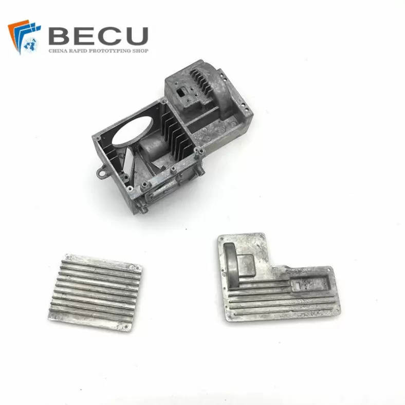
Professional Small Baler Aluminum Alloy Die-casting Mold Production
-
China Die Casting Factory Manufactures Surface Sprayed Aluminum Valve Body
-
Extrusion Die-casting Polyurethane-Coated Aluminum Alloy Profiles
-
Custom Precision Aluminum Die Cast Brackets and Finishes
-
Extrusion Die-casting Magnesium Alloy Heat Sink Shell