
CNC lathes are versatile machine tools used for various turning operations in manufacturing. They utilize computer numerical control (CNC) technology to control the cutting process, allowing for precise and automated machining of cylindrical workpieces. CNC lathes come in different layouts and configurations to accommodate specific applications. Let’s explore the layout, use, and classification of CNC lathes:
Composition and Layout Of CNC Lathes
The composition and layout of CNC lathes can vary depending on the manufacturer and the specific model.
However, the fundamental components and layout of CNC lathes are relatively consistent across most machines. Below are the main components and their typical layout in a CNC lathe:
1. Bed: The bed is the main foundation of the CNC lathe and provides support for all the other components. It is typically made of cast iron to ensure rigidity and stability. The bed is designed to dampen vibrations and promote accurate machining.
2. Headstock: The headstock is positioned at one end of the bed and contains the main spindle. It houses the spindle motor that drives the rotation of the workpiece. The headstock may have gearboxes or variable speed control to adjust the spindle speed based on the machining requirements.
3. Tailstock: The tailstock is located at the opposite end of the headstock and is used to support the other end of the workpiece. It can be adjusted along the bed’s length to accommodate workpieces of different lengths. Some tailstocks may also have a quill that moves in and out to provide additional support and stability.
4. Carriage: The carriage is mounted on the bed and can move along the bed’s length. It consists of several components:
a. Saddle: The saddle is the top part of the carriage that holds the cutting tool and moves along the bed’s length. It provides support for the cross-slide and other tool components.
b. Cross-slide: The cross-slide is mounted on the saddle and can move perpendicular to the bed’s length. It carries the cutting tool and is responsible for the crosswise movements during turning operations.
c. Tool Post: The tool post is mounted on the cross-slide and holds the cutting tool. It can be adjusted and clamped in different positions to set the tool’s cutting depth and angle.
5. Chuck: The chuck is attached to the spindle and holds the workpiece securely during machining. There are various types of chucks, such as three-jaw chucks and collet chucks, depending on the workpiece and machining requirements.
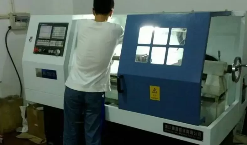
6. Control Panel: The control panel houses the CNC controller, which interprets the programmed instructions and controls the movement of the machine components and cutting tool. It allows the operator to input commands, load programs, and monitor the machining process.
7. Chip Conveyor: CNC lathes often have a chip conveyor or chip removal system to remove the chips and swarf (waste material) generated during machining. This helps keep the work area clean and prevents chip buildup.
8. Coolant System: CNC lathes are equipped with a coolant system to keep the cutting tool and workpiece cool during machining. Proper cooling helps extend tool life and improves surface finish.
9. Automatic Tool Changer (Optional): Some CNC lathes have an automatic tool changer (ATC) that allows for rapid tool changes, enabling the machine to perform multiple operations without manual intervention.
The layout of these components may vary slightly based on the machine’s design and complexity, but the fundamental elements remain consistent to ensure precise and efficient precision turning operations in CNC lathes.
Assembly of CNC Lathes
Compared with ordinary lathes, CNC lathes are still composed of spindle box, tool rest, feed transmission system, bed, hydraulic system, cooling system, lubrication system, etc., but the feed system of CNC lathes is different from that of ordinary lathes. There are essential differences in the structure of the feed system. The movement of the spindle of the ordinary lathe is transmitted to the tool rest through the wheel hanger, the feed box and the slide box to realize the longitudinal and transverse feed movement.
The CNC lathe uses the servo motor to transmit to the slide plate and the tool holder through the ball screw to realize the Z-direction (longitudinal) and X-direction (transverse) feed movement. It can be seen that the structure of the feed transmission system of the CNC lathe is greatly simplified compared with that of the ordinary lathe.
The thread processing of CNC lathes and the detection of the spindle speed are through the pulse encoder installed on the spindle box and the spindle 1:1 transmission. When the spindle rotates, the pulse encoder will send a detection pulse signal to the CNC system, so that the movement of the spindle is consistent with the speed of the spindle. The movement of the sliding plate is linked to realize the processing of the thread.
Layout of CNC Lathes
The layout of the spindle, tailstock and other components of the CNC lathe relative to the bed is basically the same as that of the ordinary lathe, but the tool rest and layout have undergone fundamental changes, because the form of the tool rest and guide rails directly affects the performance of the CNC lathe and the structure and appearance of the machine tool. In addition, CNC lathes are equipped with closed guards.
Layout Of Bed And Guide Rails
The layout of the CNC lathe bed and guide rails is based on the flat bed, which is convenient for the processing of the guide rail surface. The horizontal bed with a horizontally rotating tool holder can improve the movement accuracy of the tool holder, which can generally be used for the layout of large CNC lathes or small CNC lathes. However, the lower space of the horizontal bed is small, and the chip removal is difficult. In terms of structural dimensions, the horizontal placement of the tool rest makes the lateral dimension of the slide plate longer, thereby increasing the structural dimension in the width direction of the machine tool.
The horizontal bed is equipped with a tilting and rotating slide plate and is equipped with a tilting guide rail protective cover. On the one hand, this layout has the characteristics of good craftsmanship of the horizontal bed, and on the other hand, the size of the machine tool in the width direction is smaller than that of the horizontal slide plate. And chip removal is convenient.
The horizontal bed with inclined and rotating slide plate and the inclined bed with inclined slide plate are widely used in medium and small CNC lathes. This is because the two layout forms are easy to remove chips, hot iron chips will not accumulate on the guide rail, and it is also easy to install the automatic chip conveyor; easy to operate, easy to install the manipulator to achieve stand-alone automation; the machine tool occupies a small area and has a simple appearance , beautiful, easy to achieve closed protection.
The inclined angle of the guide rail of the inclined bed is 30 degrees, 45 degrees, 60 degrees, 75 degrees and 90 degrees (called vertical bed). If the angle of inclination is small, chip removal is inconvenient; if the angle of inclination is large, the guiding of the guide rail is poor, and the stress is also poor. The size of the inclination angle of the guide rail also directly affects the ratio of the height and width of the machine tool dimensions. Taking into account the above factors, the inclination of the bed of small and medium-sized CNC lathes should be 60 degrees.
The Layout Of The Tool Holder
As an important part of the CNC lathe, the layout of the tool holder has a great influence on the overall layout and working performance of the machine tool. At present, two-coordinate intermodal CNC lathes mostly use 12-station rotary tool holders, and there are also 6-station, 8-station, and 10-station rotary tool holders. There are two layouts of the rotary tool rest on the machine tool; one is the front of the tool rest, and the other is the rear of the tool rest. It is inconvenient to load and unload the workpiece when the tool holder is in the front. When loading and unloading the workpiece, the tool holder must be withdrawn far, and the chip removal is inconvenient;
At Be-cu.com,we use advanced equipment to offer you Unparalleled precision for producing metal and plastic machining parts
- We combine the latest CNC milling and turning processes with proprietary technology to deliver high quality, on-demand parts.
- Our team of engineers and machinists program the equipment to optimize cutting time, surface finish, and final tolerance to meet your design specifications
- We specialize in cnc precision machining, single part prototyping, short to medium production runs, manufacture parts on time, every time, so you can stay ahead of schedule
- CNC machining can create very similar parts to series parts. It is often more efficient and faster than other rapid prototyping technologies for the manufacture of a quantity of prototypes between 1 and 10 parts . We also recommend CNC machining for parts with large sizes (greater than 600 mm).
Contact Us ([email protected]) Now for your Custom CNC Machining, We are your best online cnc machining and rapid prototyping services choice!