

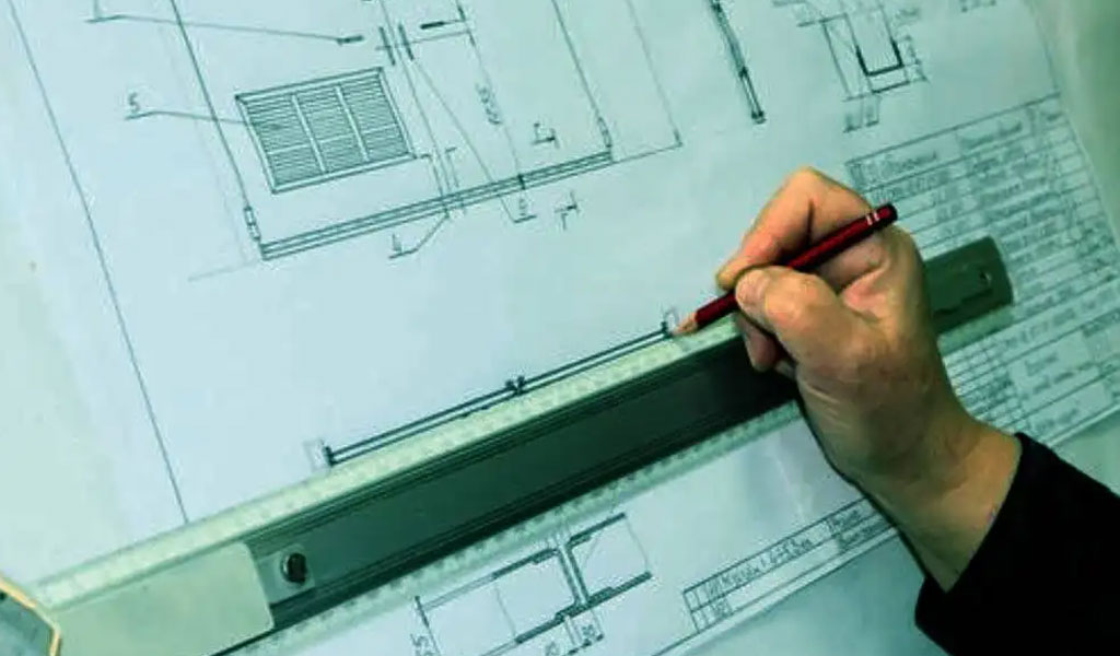
In the design process of industrial products, blueprints are always drawn up. In the past, drafting was done by hand by craftsmen, but nowadays it can be done on a computer using ‘CAD’. CAD (Management Software Computer Aided Design, MS-CAD) is the process of designing management software on a graphical development interface by designing the process structure and data structure of the management software, and finally generating a management software that can be used independently through the automatic data loading and parsing of the computer software system. The process of designing the process structure and data structure of the management software, and finally generating the management software that can be applied independently through the automatic data loading and parsing of the computer software system.Needless to say, this change has dramatically improved the efficiency and accuracy of production processes in manufacturing, for example. This section provides an overview of the CAD system, its broad types, the advantages of introducing it and points to keep in mind before introducing it.
The Define And Detail Of CAD
CAD is now an essential drafting tool in the world of manufacturing. First, let’s get an overview of CAD.
What Is CAD?
The use of computers and their graphics equipment to help designers in their design work,it is referred to as CAD. In engineering and product design, computers help designers to carry out calculations, store information and produce drawings. In design, computers are usually used to do a lot of calculations, analysis and comparisons of different solutions to decide on the best solution; all kinds of design information, whether digital, textual or graphical, can be stored in the computer’s memory or external storage and can be retrieved quickly; designers usually start their designs with sketches and the heavy work of turning sketches into working drawings can be left to the computer; The computers can be used to process graphic data related to editing, zooming in and out, panning and rotating graphics, etc.
In 1960s, the sketchpad system was developed. Based on it, it is the first CAD system “cadam” (cadam). At that time, the design of the airplane was mainly used, but since the inexpensive edition was released, it worked in various fields such as automobile industry and construction industry. In 1982, AutoCAD (AutoCAD) boasts a large worldwide share. After that, various CAD has been born according to the technological improvement and the diversification of industrial products to be designed. Most of the products produced as industrial products can be said to be the products of CAD.
Development Overview Of CAD – Computer Aided Design
In the 1950s the first computer graphics system was born in the USA and passive computer-aided design technology began to emerge with simple drawing output functions. manual cursors, graphics input boards and many other forms of graphics input devices, which contributed to the development of CAD technology.
In the 1980s, with the advent of microprocessors and memory devices made of powerful super-scale integrated circuits, engineering workstations were introduced and CAD technology gradually became popular in small and medium-sized enterprises. Some standard graphic interface software and graphic functions were introduced one after another, which played an important role in promoting CAD technology, software transplantation and data sharing; the system structure changed from a single function in the past to a comprehensive function, and a computer-aided design and aided manufacturing became a computer integrated manufacturing system;the application of curing technology, network technology, multi-processor and parallel processing technology in CAD greatly improved the performance of CAD systems.
The introduction of artificial intelligence and expert system technology into CAD has led to the emergence of intelligent CAD technology, which has greatly enhanced the problem solving capabilities of CAD systems and automated the design process.
CAD has been used in a wide range of fields such as architectural design, electronics and electricity, scientific research, mechanical design, software development, robotics, clothing industry, publishing, factory automation, civil engineering, geology and computer art.
The Basic Technology Of CAD
Basic techniques Mainly include interaction techniques, graphic transformation techniques, surface modelling and solid modelling techniques.
- Interaction techniques:In computer-aided design, interaction techniques are essential. An interactive cad system is one in which the user can use the computer system to design in such a way that information can be exchanged between man and machine in a timely manner. With an interactive system, people can conceptualise, prototype and modify their designs at the same time, and can see the results of each step on the graphics terminal screen at any time, which is very intuitive.
- Graphic transformation: The main function of the graphic transformation is to link the user’s coordinate system with the coordinate system of the graphic output device; to translate, rotate, scale and perspective transform the graphic; to realise the graphic transformation through matrix operations.
- Solid modelling: Solid modelling is a key technology for building 3D solid models in the fields of computer vision, computer animation and computer virtual reality. Solid modelling is a technology that describes the shape and properties of a geometric model and stores the information in a computer, which generates a realistic and visual 3D graphic.
CAD System Components
Usually based on an interactive computer system with graphic functions, the main equipment includes: computer mainframes, graphic display terminals, graphic input boards, plotters, scanners, printers, tape drives, and various types of software.
Engineering Workstations
An engineering workstation is generally defined as a single-user interactive computer system with supercomputer functions and three-dimensional graphics processing capabilities. It has strong computing power, uses standard graphics software, has high-resolution display terminals, can be linked to work on a resource-sharing local area network and has formed the most popular cad system.
Personal Computers
The personal computer (pc) system is inexpensive, easy to operate and flexible in use. after the 80s, the performance of the pc is constantly renovated, hardware and software development is rapid, coupled with the application of graphics cards, high-resolution graphics displays, and the development of pc network technology, the cad system formed by the pc body has emerged in large numbers, and is on the rise.
Graphical Input And Output
- Role: In addition to the computer host and general peripherals, computer-aided design mainly uses graphics input and output devices. Interactive graphics systems are particularly important for cad. The general role of graphic input devices is to feed the coordinates of points on a plane into the computer.
- Common devices: Common input devices include keyboards, light pens, touch screens, joysticks, tracking balls, mouse devices, graphics input boards and digitisers.
- Equipment classification: Graphics output devices are divided into two categories: soft copy and hard copy.
- Soft copy devices refer to a variety of graphic display devices, which are essential for human-computer interaction.
- Hard copy devices are often used as an accessory to graphic displays, which make copies of the images on the screen for preservation.
Three types of graphic displays are commonly used: directional beam displays, memory tube displays and raster scan displays.
- The earliest application of directional beam display, in order to make the image clear, the electronic beam must constantly redraw graphics, so also known as refresh display, it is easy to erase and modify the graphics, suitable for interactive graphics means.
- Memory tube displays save images without having to be refreshed, so they can display large amounts of data and are less expensive.
- The raster scanning system provides colour images, the image information can be stored in the so-called frame buffer memory and the resolution of the images is high.
CAD Software
In addition to the computer’s own software such as operating systems and compiled programs, cad mainly uses three types of software: interactive graphics display software, cad application software and data management software.
- The interactive graphics display software is used for windowing, editing and viewing the graphics display, transforming and modifying the graphics, as well as the corresponding human-computer interaction.
- The cad application software provides geometric modelling, feature calculation and drawing functions to complete a variety of specialised designs for various specialist areas. The four elements that make up an application are: algorithms, data structures, user interfaces and data management.
- Data management software is used to store, retrieve and process large amounts of data, including textual and graphical information. For this purpose, an engineering database system is required. It has the following characteristics compared to a normal database system: more diverse data types, complex entity relationships during the design process, frequent changes in values and data structures in the library, and a mainly real-time interactive processing by the designer.
The Drawing Function Of CAD
CAD System Functions
The functions of modern CAD systems include:
- Reuse of design components
- Ease of design modification and versioning
- Automatic generation of standard components of the design
- Validation/verification of designs against specifications and design rules
- Simulation of designs without building a physical prototype
- Automatic design of assemblies (piles of parts or other assemblies)
- Output of engineering documentation, e.g. manufacturing drawings, Bill of Materials
- Direct output of design to production equipment
- Direct output to rapid prototyping or rapid manufacture of industrial prototype machines
The Types Of CAD Systems
- Information retrieval CAD systems: These are mainly used to design products that have been standardised and serialised to a high degree. The working principle is that the standardised drawings of the finalised product are stored in the computer as graphic information. The necessary information is entered at the time of design and, after the computer has carried out the necessary calculations, the best standard drawing is automatically retrieved.
- Human-Computer Interaction CAD System: The working principle of the human-computer interaction CAD system is that the designer determines and describes the design model according to his knowledge and experience, and then the computer retrieves a large amount of information about the product and performs high-speed calculations on the relevant data and formulas; through the display of sketches and standard diagrams, the designer analyses them using the experience accumulated during his long work. With the keyboard or mouse and other input devices, man-machine dialogue directly on the graphics of real-time modification, the computer according to the instructions to respond to reorganise the display, repeated cycle, and gradually improve.
- Intelligent CAD systems: At this stage, the application of artificial intelligence is mainly reflected in the form of expert systems, i.e. the organic combination of expert systems with the original CAD system. An expert system is a computer software system that enables a computer to use the expertise and reasoning and judgement of an expert to carry out design work. In an intelligent CAD system, the expert system undertakes judgement work that requires reasoning based on knowledge and experience, mainly design process decisions (to solve design thinking problems), design technology decisions (decisions to solve specific technical problems encountered in design) and various result evaluations. Problems that can be described by mathematical models are solved by the usual CAD-aided design systems.
A List Of The 4 Most Commonly Used CAD Software
AutoCAD is internationally renowned for its 2D and 3D CAD design software. It is an automatic computer-aided design software first produced in 1982 by the US company Autodesk for 2D drafting, detailed drawing, design documentation and basic 3D design.
It has now become a widely popular international drawing tool. The .dwg file format has become the de facto standard format for 2D drawing.
AutoCAD has a good user interface and its multi-document design environment allows even non-computer professionals to learn to use it very quickly. It supports more than 40 kinds of graphic display devices with resolutions from 320 x 200 to 2048 x 1024, as well as more than 30 kinds of digital instruments and mouse devices, and dozens of plotters and printers, which has created the conditions for the popularity of AutoCAD.
In the mechanical field AutoCAD is one of the most commonly used software applications for drawing and modelling, and by using AutoCAD software, the quality of mechanical design is largely enhanced. Not only does AutoCAD software support the application of function key combinations and common shortcut keys, allowing users to meet the functional interaction input control options in the software. The software can also provide the operator with the ability to draw graphics, support secondary development and scripting runs.

HaoChen CAD is a famous Chinese CAD design software, developed by Suzhou HaoChen Software Co Ltd, the latest version is HaoChen CAD 2012. In 2010, HaoChen received financial support from the Ministry of Industry and Information Technology to develop 3D architectural collaborative design software, and in 2012 will launch a full set of solutions integrating professional software and collaborative design and management systems for architecture, structure, plumbing, heating, electricity, sunlight and energy saving.
The first version was developed by Guangzhou Zhongwang Longteng Software Co. and launched in 2001, the latest version is Zhongwang CAD 2011.
It is widely used in communication, construction, coal, water conservancy and hydropower, electronics, machinery, moulds and other survey and design and manufacturing fields. In 2010, MicroStation acquired the famous American 3D CAD/CAM design software company VX at a cost of US$10 million, and launched MicroStation 3D 2010 version in August 2010, since then, MicroStation has been involved in the field of 3D CAD design software.
MicroStation is an international 2D and 3D CAD design software on par with AutoCAD, the first version was developed by the Bentley brothers in 1986. Its proprietary format is DGN and is compatible with AutoCAD’s DWG/DXF and other formats. MicroStation is the foundation platform for Bentley Engineering Software Systems’ solutions in the areas of architecture, civil engineering, transportation, process plants, discrete manufacturing, government, utilities and telecommunications networks. For example, with third-party plug-ins such as TurnTool, you can publish online 3D display cases directly from MicroStation.
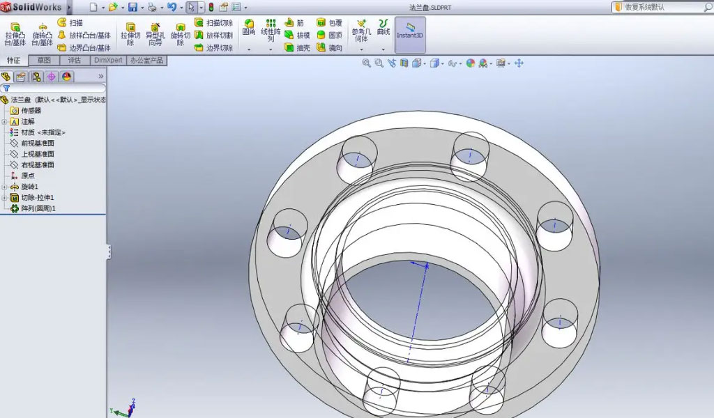
Solidworks software is a powerful, component-rich computer-aided design software with powerful parametric design features that integrate product design, manufacturing and production management. Solidworks is a parameter-driven design model that allows you to improve your design by modifying relevant parameters and supports dynamic modification of the design.
The software contains a rich library of standard parts, and the user can also expand the custom library at will, thus reducing unnecessary repetitive design work, effectively shortening the design cycle and improving design efficiency, the software can be dynamic interference checks and gap detection of moving parts through arbitrary rotation and cutting, and problems are immediately corrected, putting the “trial process “Solidworks is an innovative industrial design tool that organically combines product modelling and functional design.
The Types And Features Of CAD
There are different types of CAD, including.
2D CAD (2DCAD) and 3D CAD (3DCAD)
There are two types of CAD: 2D CAD, which handles 2D data, and 3D CAD, which can also handle 3D.
2D CAD
This is the simplest and most simple type of CAD. It uses lines and arcs to create 2D figures such as floor plans and 3D drawings, and is the easiest of the CAD types to input data into, with some software available free of charge, making it easy to adopt.
If you already have experience in creating drawings by hand, you should be able to make a smooth transition to CAD, as the basic methods of expression, such as lines and planes, are almost identical.
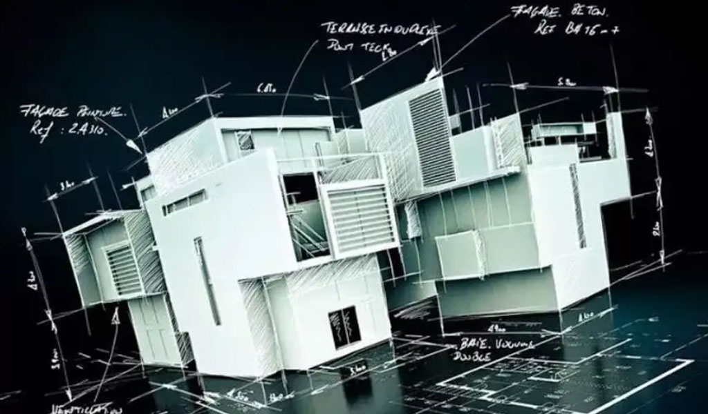
3D CAD
3D CAD is used for three-dimensional drafting. Compared to 2D CAD, 3D CAD is used in a wide range of workplaces because it is easier to draw detailed and complex shapes and to visualise the final product. 2D data can also be created from 3D data.
On the other hand, the high PC specifications required and the high price of the tools themselves make their introduction costly. They are divided into ‘high-end CAD’, ‘mid-range CAD’ and ‘low-end CAD’ depending on the processing they perform.
Dedicated CAD And General-Purpose CAD
Depending on the product, CAD can be divided into dedicated CAD for specific sectors and industries and general-purpose CAD for use in a wide range of fields.
- Dedicated CAD:There are also CADs dedicated to drafting in different trades, such as architecture, civil engineering, plumbing and electrical engineering. Depending on their purpose, they are called architectural CAD, mechanical CAD, civil engineering CAD, electrical CAD or apparel CAD. CAD systems are common to general-purpose CAD systems in that they can be used for design and drafting, but they also have a unique feel and are preloaded with functions commonly used in various industries, thereby improving work efficiency.
- General-purpose CAD:General-purpose CAD is a highly versatile CAD system that can be used in any field. On the other hand, it has many built-in functions and it may take some time to master drafting operations.
The Advantages Of Implementing CAD
Machining programmes can be stored as data on the computer, so it is possible to modify data used in the past and make design changes, or to create new machining programmes using past data. In addition, CAD/CAM can simulate operations on a PC before creating NC data, pouring it into the machine tool and moving on to the machining process.
This makes it possible to check the machine’s operation and the resulting machining record before the actual work is carried out. Furthermore, complex calculations can be done by computer, which reduces time and errors. With some operating knowledge, machining of special shapes is also possible. And as the machining time forecast can also be checked on the computer, it is easier to adjust customer delivery times.Here are some typical benefits of introducing CAD.
Increased Work Efficiency
In contrast to manual drafting by designers, the work can be made significantly more efficient. For example, with paper drawings, making corrections and changes can be a challenge. In many cases, pencil marks and other smudges are left behind, making the drawings difficult to read.
With CAD data, on the other hand, line segments entered in error can be deleted, so work can proceed while making corrections. Naturally, the finished drawings are consistent in dimension and area, and calculations are easy. Human error is also less likely to occur, resulting in fewer rework. Another feature is that the legibility of the drawings does not depend on the individual. Another major advantage is the ability to download and use CAD data for parts that other companies have made available to the public.
The ability to use such data in different ways is another feature of digital technology. In addition, the time required to acquire skills is shorter than with manual drafting, which required a craftsman-like discipline. Of course, it is not easy to become a professional CAD operator with no experience, but the advantage is that the learning costs are relatively low compared to the days of paper-based drafting.
Smooth Management And Sharing Of Drawings
Drawings are managed and shared as data rather than on paper, making them easy to handle.
Anyone with viewing software can open them, so they can be sent by e-mail or other means to distant personnel for checking.
This eliminates the need to duplicate the drawings and send them by post. In recent years, some sites have been using tablets to share drawing data. In addition to design, the digitalisation of drawing transfer to subsequent processes such as CNC machining and sheet metal fabrication will also increase efficiency for the companies collaborating with them.
In this way, sharing data internally and externally can also help collaborative work on design. Furthermore, paper drawings are time-consuming to rewrite and revise, whereas CAD is digital data and can be easily edited. It is also possible to easily add pens to drawing data provided by customers, or to reuse drawings of similar products that have been created in the past. Another advantage is that there is no need to save physical space for the storage of drawings, and searchability is improved.
CAD Model Data
CAD design software will provide some models, but more models need to be downloaded from the internet. Some domestic forums and platforms will also provide relevant models for download, although the accuracy and richness of the content is yet to be improved.
However, if the enterprise has a variety of CAD systems in parallel, then it is necessary to configure a unified, cross-platform parts data repository with the ability to export the model data from the standard parts library and the outsourced parts library to the 3D configuration system in the original CAD data format, such as the mainstream Autodesk Inventor, SolidWorks, CATIA, SolidEdge, Pro/E, AutoCAD, UG NX, Onespace, etc., to help designers complete their design work faster and improve efficiency. The Internet-based PLM parts data resource platform – PARTcommunity seems to build a huge and rich 3D model with the power of the cloud, and in foreign countries, this network service is called “parts library” or “data resource warehouse”. Among PLM users in Europe, the US and Japan, PARTcommunity (PCOM for short) is no less well-known than the BLOG and SNS platforms we know today.
In early 2010 PARTcommunity 2.0 (PCOM 2.0) was officially launched in Germany and its PCOM 2.0 site in simplified Chinese was officially set up in Beijing (linkable.partcommunity), the platform was developed by Beijing Lingrui Hongxiang Technology Co. The platform is developed by Beijing Lingrui Hongxiang Technology Co. PARTsolutions also provides an interface to the original data format of some of the Chinese modelling systems such as Thinkdesign (Think3), VX, etc.
Differences Between CAM, CAD/CAM And CAE
CAM, CAD/CAM and CAE are software packages related to CAD. Here is a brief overview of each and how they differ from CAD
CAM.
Computer Aided Manufacturing in Japanese. This is software for creating numerically controlled machining programmes (toolpaths) for NC machine tools used in lathe turning, etc., and is often used in the manufacturing industry. In concrete terms, the first step is to create design drawing data in CAD, which is then loaded into CAM. Here, the drawing information is converted into the language for the machine tool. The machine tool is then instructed how to move, and numerically controlled automatic machining takes place. In this way, CAD plays the role of ‘design’ and CAM the role of ‘manufacturing’. There are different types of CAM, such as 2D/3D, dedicated and general-purpose. HSM is a typical tool. The appeal of this CAM is that it can smoothly link data with CAD systems such as SOLIDWORKS.
CAD/CAM.
CAD/CAM is software that has both CAD and CAM functions. Normally, design drawing data created in CAD is loaded into CAM, where data conversion is carried out before moving on to cnc machining operations. With CAD/CAM, on the other hand, a series of these operations can be carried out in a single software package. As it is an integrated system, there is no need to worry about data compatibility and a high rate of consistency is maintained, so that if any corrections or changes are required in the CAM stage, there is no need to start up CAD again, make corrections and then load the data into CAM. A well-known CAD/CAM software is Autodesk’s Fusion360. This software has become popular in the CAM industry due to its versatility and its ability to handle 2D and 3D data.
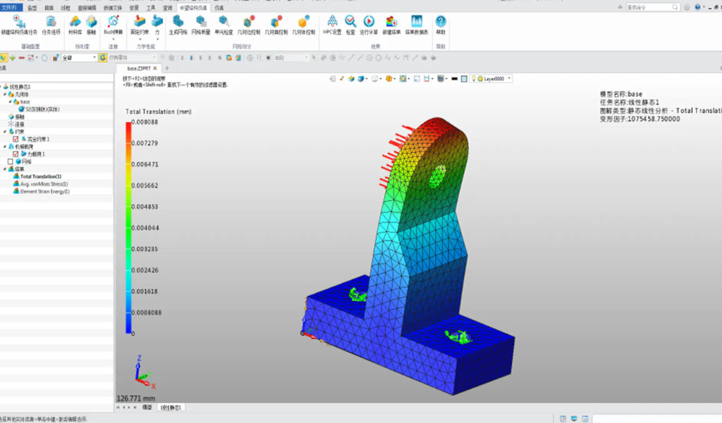
CAE.
CAE is used to analyse and simulate the pressure and heat resistance of products. CAE stands for ‘Computer Aided Engineering’. It covers a wide range of fields, including displacement fields, stress fields, temperature fields and electromagnetic fields. The results of mathematical modelling and analysis can be used to reduce the cost of product prototyping and to provide material for investigation in case of defects. CAE is essentially used prior to drafting and design. Therefore.
- Simulation by CAE
- Drafting and design using CAD
- Manufacturing programming with CAM
The order in which they are used is as follows.