
The ACME thread is a trapezoidal thread form widely recognized in mechanical engineering for its strength, ease of manufacture, and versatility in applications requiring significant load-bearing capacity or precise linear motion.
Named after the Acme Screw Machine Company, which developed it in 1894, this thread profile has become a cornerstone in industries ranging from machinery to aerospace. Standardized initially in 1921, the ACME thread remains a dominant inch-based trapezoidal thread system globally, even as metric threads have overtaken other thread types in many applications.
This article provides a comprehensive exploration of the ACME thread dimensions chart for both internal and external threads, delving into its profile, formulas, classes, sizes, and practical applications. It aims to serve as an authoritative resource for engineers, machinists, and researchers by presenting detailed data, mathematical underpinnings, and comparative analyses.
BE-CU.com
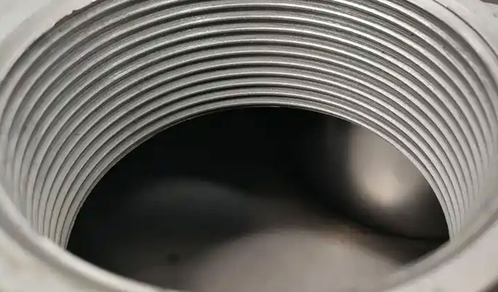
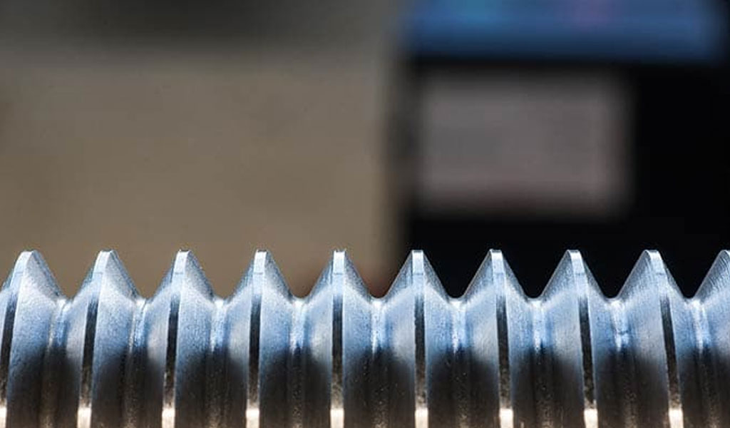
The ACME thread is characterized by its distinctive trapezoidal shape, featuring a 29-degree included flank angle and, in its general-purpose form, a thread height equal to half the pitch. Unlike the square threads it was designed to replace, the ACME thread offers superior manufacturability and wear resistance, making it ideal for power screws, lead screws, and other mechanisms requiring controlled motion or high torque transmission. Its broad, flat crests and roots enhance its strength, while the 29-degree angle facilitates smoother engagement compared to the sharper profiles of V-threads. The ACME thread’s standardization under ASME/ANSI B1.5 for general-purpose threads and ASME/ANSI B1.8 for stub variants ensures consistency across industries, with dimensions expressed in inches to maintain compatibility with imperial systems.
Historical Context and Development
The ACME thread emerged during the late 19th century as a response to the limitations of square threads, which, while strong, were difficult to machine and prone to rapid wear. In 1894, the Acme Screw Machine Company, under the guidance of engineer William Sellers, introduced the ACME thread as a robust alternative. Sellers aimed to create a thread form that balanced strength, manufacturability, and durability, resulting in a trapezoidal profile that quickly gained traction.By 1921, the thread was standardized in the United States, cementing its status as a preferred choice for lead screws and power transmission components.
Unlike metric trapezoidal threads (e.g., the ISO-standardized Tr thread with a 30-degree angle), the ACME thread retained its inch-based dimensions, reflecting its origins in American industrial practice.
The evolution of the ACME thread reflects broader trends in mechanical engineering, where standardization and interchangeability became critical as industries scaled. Its adoption in applications such as lathes, milling machines, jacks, and aircraft flaps underscores its versatility. Over time, refinements led to the development of specialized variants—General Purpose (G), Centralizing (C), and Stub ACME—each tailored to specific operational demands. These variants, governed by distinct standards, offer engineers a range of options to optimize performance, whether for free movement, high-load stability, or compact design.
ACME Thread Profile and Geometry
The ACME thread’s defining feature is its trapezoidal profile, which distinguishes it from triangular (V-shaped) threads and square threads. The thread’s geometry includes a 29-degree included angle between the flanks, a thread height of 0.5P (where P is the pitch) in general-purpose applications, and flat crests and roots. This configuration provides a wider base than a square thread of equivalent size, enhancing load-bearing capacity and reducing stress concentrations. The flat apex and valley also simplify machining compared to square threads, which require precise tool geometry that complicates production.
Mathematically, the basic dimensions of the ACME thread profile are derived from the pitch (P), defined as the distance between adjacent thread crests or, equivalently, the reciprocal of threads per inch (TPI). For a single-start thread, the lead—the axial distance advanced per revolution—equals the pitch. The fundamental formulas for the ACME thread profile are:
- Pitch (P): P=1/TPI
- Thread Height (h): h=0.5P
- Major Diameter (D): Nominal diameter of the thread
- Pitch Diameter (D₂): D2=D−h=D−0.5P
- Minor Diameter (D₁): D1=D−2h=D−P
These dimensions represent the “basic” profile, excluding allowances and tolerances, which are adjusted based on the thread class (e.g., 2G, 3G, 4G). The 29-degree flank angle ensures a balance between strength and manufacturability, while the flat crests and roots—typically 0.3707P wide at the crest of the external thread and slightly wider at the internal thread—provide clearance and reduce wear.
For multiple-start ACME threads, the lead increases proportionally to the number of starts (n), such that:
- Lead (L): L=n⋅P
This adjustment allows for faster traversal speeds, a feature exploited in applications like CNC machinery, though it complicates internal thread tolerances, as discussed later.
Designation System
ACME threads follow a standardized designation system that conveys critical information about their size, pitch, series, and precision class. The format is typically expressed as:
D−TPI−Series−Class D
- D: Nominal major diameter in inches (e.g., 1/2, 0.500, or fractional equivalents from 1/4 to 5 inches)
- TPI: Threads per inch (e.g., 10, indicating a pitch of 0.1 inches)
- Series: G (General Purpose), C (Centralizing), or Stub
- Class: Precision level (e.g., 2G, 3G, 4G for General Purpose; 2C, 3C, 4C for Centralizing)
For example, “1/2-10-ACME-2G” denotes a thread with a 0.5-inch major diameter, 10 threads per inch, General Purpose series, and Class 2G fit. Additional qualifiers, such as “-LH” for left-hand threads or “L” followed by lead distance for multiple-start threads (e.g., “1/4-0.0625P-0.1875L-ACME”), provide further specificity. This system ensures clarity in design and manufacturing, aligning with ASME/ANSI standards.
Thread Series and Classes
The ACME thread family encompasses three primary series, each with distinct characteristics and precision classes:
General Purpose (G) Series
The G series, standardized under ASME/ANSI B1.5, is the most widely used ACME thread type. Designed for interchangeability and ease of assembly, it features a 29-degree angle and a thread height of 0.5P. It is intended for applications where the nut and screw are independently supported, avoiding radial loads that could cause wedging. The series includes three precision classes:
- 2G: The preferred class for general applications, offering moderate clearance for free movement and ease of assembly.
- 3G: Tighter tolerances than 2G, reducing backlash for improved precision.
- 4G: The highest precision in the G series, minimizing end play for applications requiring exact positioning.
Centralizing (C) Series
Also governed by ASME/ANSI B1.5, the C series shares the G series’ basic dimensions but restricts clearance at the major diameter of both internal and external threads. This design prevents flank wedging under radial loads, making it suitable for high-load scenarios like feed screws. Precision classes include:
- 2C: Standard fit with reduced clearance compared to 2G.
- 3C: Enhanced precision over 2C.
- 4C: Maximum precision, with additional classes (5C, 6C) available but not recommended for new designs.
Stub ACME Series
Defined by ASME/ANSI B1.8, the Stub ACME thread features a reduced thread height—0.3P instead of 0.5P—resulting in a shorter, truncated profile. This compactness suits applications with limited space or where shallow threads are mechanically advantageous. Unlike the G and C series, it has a single precision class, aligned with 2G tolerances, though Modified Forms (M1, M2) offer alternative heights (0.375P and 0.25P, respectively).
Dimension Charts and Tolerances
The following tables present recommended industry-standard sizes for internal and external ACME threads per ASME/ANSI B1.5 (General Purpose) and B1.8 (Stub), with all dimensions in inches. These charts include major, pitch, and minor diameters, along with tolerances for each class, providing a practical reference for design and machining.
External ACME Thread General Purpose Size Chart (ASME/ANSI B1.5)
| Nominal Size (D) | TPI | Pitch (P) | Major Diameter (Max/Min) | Pitch Diameter (Max/Min) | Minor Diameter (Max/Min) | Class |
|---|---|---|---|---|---|---|
| 1/4 | 16 | 0.0625 | 0.2500 / 0.2410 | 0.2188 / 0.2128 | 0.1875 / 0.1795 | 2G |
| 1/4 | 16 | 0.0625 | 0.2500 / 0.2430 | 0.2188 / 0.2148 | 0.1875 / 0.1815 | 3G |
| 1/4 | 16 | 0.0625 | 0.2500 / 0.2450 | 0.2188 / 0.2168 | 0.1875 / 0.1835 | 4G |
| 1/2 | 10 | 0.1000 | 0.5000 / 0.4880 | 0.4500 / 0.4420 | 0.4000 / 0.3880 | 2G |
| 1/2 | 10 | 0.1000 | 0.5000 / 0.4910 | 0.4500 / 0.4450 | 0.4000 / 0.3910 | 3G |
| 1/2 | 10 | 0.1000 | 0.5000 / 0.4940 | 0.4500 / 0.4480 | 0.4000 / 0.3940 | 4G |
| 1 | 5 | 0.2000 | 1.0000 / 0.9820 | 0.9000 / 0.8880 | 0.8000 / 0.7820 | 2G |
| 1 | 5 | 0.2000 | 1.0000 / 0.9870 | 0.9000 / 0.8930 | 0.8000 / 0.7870 | 3G |
| 1 | 5 | 0.2000 | 1.0000 / 0.9920 | 0.9000 / 0.8980 | 0.8000 / 0.7920 | 4G |
Internal ACME Thread General Purpose Size Chart (ASME/ANSI B1.5)
| Nominal Size (D) | TPI | Pitch (P) | Major Diameter (Min/Max) | Pitch Diameter (Min/Max) | Minor Diameter (Min/Max) | Class |
|---|---|---|---|---|---|---|
| 1/4 | 16 | 0.0625 | 0.2500 / 0.2600 | 0.2188 / 0.2248 | 0.1875 / 0.1955 | 2G |
| 1/4 | 16 | 0.0625 | 0.2500 / 0.2570 | 0.2188 / 0.2228 | 0.1875 / 0.1935 | 3G |
| 1/4 | 16 | 0.0625 | 0.2500 / 0.2540 | 0.2188 / 0.2208 | 0.1875 / 0.1915 | 4G |
| 1/2 | 10 | 0.1000 | 0.5000 / 0.5140 | 0.4500 / 0.4580 | 0.4000 / 0.4120 | 2G |
| 1/2 | 10 | 0.1000 | 0.5000 / 0.5090 | 0.4500 / 0.4550 | 0.4000 / 0.4090 | 3G |
| 1/2 | 10 | 0.1000 | 0.5000 / 0.5040 | 0.4500 / 0.4520 | 0.4000 / 0.4060 | 4G |
| 1 | 5 | 0.2000 | 1.0000 / 1.0220 | 0.9000 / 0.9120 | 0.8000 / 0.8180 | 2G |
| 1 | 5 | 0.2000 | 1.0000 / 1.0170 | 0.9000 / 0.9070 | 0.8000 / 0.8130 | 3G |
| 1 | 5 | 0.2000 | 1.0000 / 1.0120 | 0.9000 / 0.9020 | 0.8000 / 0.8080 | 4G |
Stub ACME Thread Dimensions (ASME/ANSI B1.8)
| Nominal Size (D) | TPI | Pitch (P) | Thread Height (h) | Major Diameter (Max/Min) | Pitch Diameter (Max/Min) | Minor Diameter (Max/Min) |
|---|---|---|---|---|---|---|
| 1/4 | 16 | 0.0625 | 0.01875 (0.3P) | 0.2500 / 0.2410 | 0.2313 / 0.2253 | 0.2125 / 0.2045 |
| 1/2 | 10 | 0.1000 | 0.0300 (0.3P) | 0.5000 / 0.4880 | 0.4700 / 0.4620 | 0.4400 / 0.4280 |
| 1 | 5 | 0.2000 | 0.0600 (0.3P) | 1.0000 / 0.9820 | 0.9400 / 0.9280 | 0.8800 / 0.8620 |
Formulas and Calculations
To compute ACME thread dimensions beyond basic values, engineers rely on formulas that incorporate allowances (es) and tolerances, adjusted by class and series. For General Purpose threads:
- External Thread Major Diameter Allowance: es=0.020P0.5 es = 0.020P^{0.5} es=0.020P0.5 (Class 2G)
- Pitch Diameter Tolerance: Varies by class (e.g., 0.0060 for 2G, 0.0040 for 3G, 0.0020 for 4G at 10 TPI)
- Root-Crest Clearance: Minimum 0.01 inch for TPI ≤ 10, 0.005 inch for finer pitches
For multiple-start threads, internal thread allowances increase by a factor K⋅es K \cdot es K⋅es, where K=0.5 K = 0.5 K=0.5 (2 starts), 0.75 (3 starts), or 1.0 (4+ starts). Stub ACME threads adjust the height term in the formulas:
- Stub Height: h=0.3P
- Pitch Diameter: D2=D−0.3P
- Minor Diameter: D1=D−0.6P
These calculations ensure threads meet functional requirements, such as load capacity or positional accuracy, while adhering to manufacturing constraints.
Applications and Advantages
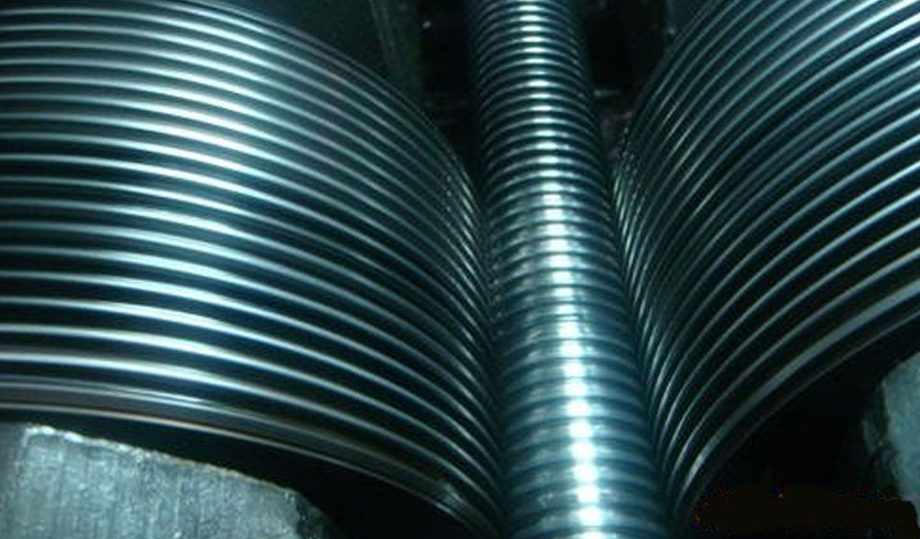
ACME threads excel in applications requiring robust power transmission or precise linear motion. Common uses include:
- Lead Screws: In lathes and CNC machines for controlled movement.
- Jacks and Presses: For lifting or pressing with high torque.
- Valve Stems: In oil and gas systems for reliable sealing.
- Aircraft Flaps: For durable actuation under load.
Advantages include higher strength than square threads, easier machining than square or V-threads, and compatibility with split nuts for wear compensation. However, lower efficiency due to friction and potential radial loading in G-series threads are notable drawbacks, mitigated by the C-series design.
Conclusion
Compared to metric trapezoidal threads (Tr, 30-degree angle), ACME threads offer greater standardization in imperial systems and a slightly shallower angle for improved wear resistance.
Versus square threads, ACME provides easier production and better wear adjustment, though at reduced efficiency. The Stub ACME’s compact height contrasts with the full 0.5P height of G and C series, trading depth for space efficiency.
The ACME thread’s enduring relevance stems from its balanced design, standardized dimensions, and adaptability across industries. This article’s detailed charts and formulas equip practitioners with the tools to specify, design, and machine ACME threads effectively, ensuring performance in demanding applications.


The Detail Of BE-CU Cnc Machining Shop
BE-CU.COM – As an accomplished CNC machining Service Manufacturer and CNC shop, BE-CU Prototype has been specialized in OEM CNC lathing, custom CNC machining parts production and rapid CNC machining services China for over 35 years and always maintaining the highest standard in delivery speed and reliable quality of precision CNC manufacturing components. With the help of high-level technology and efficient equipment, as well as rigorous attitude, BE-CU passed the ISO9001:2015 quality certification, which supports the long-term development of CNC milling services, CNC turning services, CNC milling-turning, CNC drilling services, 3/4/5 axis machining, gear machining services, CNC machining China custom parts and service, small parts machining, etc.Our CNC machining products can be utilized in a broad range of industries. Contact us for email: [email protected]

-

3-Way Centrifugal Compressor Closed Impeller By 5 Axis Machining
-

3/4/5 Axis Precision Milling Custom Vehicle Parts
-

3D Flexible Welding Platform By Large Machining
-

3D Printed Inconel Exhaust Manifold
-

3D Printing And CNC Machining Custom Black PPS Valve
-

3D Printing Full Transparent Acrylic Lampshade Model
-

4 Axis CNC Machining Titanium Grade 5 Mobile Phone Buttons
-

4 Axis Machining Highly Transparent Acrylic LED Tunnel Light Lens