
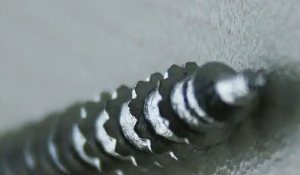
Buttress threads, recognized for their distinctive asymmetrical profile, represent a specialized category of screw threads engineered to manage high axial loads predominantly in one direction.This design, often referred to as a sawtooth or breech-lock thread form, features a steep leading flank (typically perpendicular or near-perpendicular to the screw axis) and a shallower trailing flank, which together enhance load-bearing capacity and reduce friction during engagement.
These threads find extensive application in mechanical systems such as screw jacks, vises, hydraulic presses, and oilfield tubing, where unidirectional force transmission and structural integrity are paramount.
This article delves into the metric dimensions of buttress threads, their characteristic angles, and the methodologies for calculating their parameters, providing a comprehensive resource for engineers, machinists, and researchers. Accompanying this discussion are detailed charts and a conceptual framework for a calculator to simplify thread sizing.
Historical Context and Development
The buttress thread’s origins trace back to applications requiring robust unidirectional load resistance, notably in artillery breech mechanisms during the 19th and early 20th centuries.
The design’s ability to withstand significant thrust while facilitating rapid disengagement made it ideal for screw-type breechblocks. Over time, its utility expanded into industrial machinery, with standards evolving to accommodate both imperial and metric systems.
In the metric domain, organizations such as the Deutsches Institut für Normung (DIN) and the International Organization for Standardization (ISO) have codified specifications, notably DIN 513 for S-series metric buttress threads and DIN 2781 for 45° variants used in hydraulic systems. These standards reflect a synthesis of practical engineering needs and theoretical precision, balancing manufacturability with performance.
The asymmetrical geometry of buttress threads distinguishes them from symmetrical profiles like the ISO metric thread (with its 60° V-shape) or the trapezoidal Acme thread. While the latter excel in bidirectional load scenarios, buttress threads prioritize strength in one direction, sacrificing some capacity in the reverse due to higher friction on the trailing flank. This trade-off, however, enables superior load distribution and self-locking properties, critical in high-stakes applications.
Anatomy of Buttress Threads
A buttress thread’s profile comprises several key geometric elements:
- Major Diameter (d or D): The largest diameter of the thread, measured crest-to-crest for external threads or root-to-root for internal threads.
- Minor Diameter (d₁ or D₁): The smallest diameter, measured root-to-root for external threads or crest-to-crest for internal threads.
- Pitch (P): The axial distance between corresponding points on adjacent thread crests, typically expressed in millimeters for metric threads.
- Thread Height (H): The radial distance from the major to minor diameter, determined by the pitch and flank angles.
- Pressure Flank: The load-bearing face, often perpendicular (0°) or slightly slanted (e.g., 3° or 7°), designed to resist axial thrust.
- Trailing Flank: The clearance face, inclined at a steeper angle (e.g., 30°, 45°), which minimizes friction during disengagement.
- Pitch Diameter (d₂ or D₂): The theoretical diameter where the thread thickness equals the space between threads, critical for gauging and tolerance.
The asymmetry arises from the differing angles of the pressure and trailing flanks. For instance, the DIN 513 S-series specifies a 3° pressure flank and a 30° trailing flank, while ANSI B1.9 (American standard) employs a 7°/45° configuration. These angles influence the thread’s mechanical behavior, with shallower pressure flanks enhancing load capacity and steeper trailing flanks easing manufacture.
Metric Standards and Specifications
Metric buttress threads adhere to several standardized forms, each tailored to specific applications. Below is an overview of prominent standards:
DIN 513: S-Series Metric Buttress Thread (3°/30°)
The DIN 513 standard defines the S-series buttress thread, characterized by a 3° pressure flank and a 30° trailing flank. This configuration optimizes load transfer in applications like spindle presses and lifting systems. The thread’s metric dimensions include nominal sizes ranging from 10 mm to 300 mm, with pitches varying from 2 mm to 24 mm depending on diameter.
A representative table of DIN 513 dimensions (medium fit, normal engagement length) is provided below:
| Nominal Diameter (mm) | Pitch (mm) | Major Diameter (d, mm) | Pitch Diameter (d₂, mm) | Minor Diameter (d₃, mm) | Thread Height (H, mm) |
|---|---|---|---|---|---|
| 10 | 2 | 10.00 | 9.026 | 8.252 | 0.874 |
| 20 | 3 | 20.00 | 18.539 | 17.078 | 1.461 |
| 40 | 7 | 40.00 | 37.069 | 34.138 | 2.931 |
| 80 | 10 | 80.00 | 75.813 | 71.626 | 4.187 |
| 120 | 14 | 120.00 | 113.739 | 107.478 | 6.261 |
Notes: Values are nominal and subject to tolerances per DIN 513:1985. Thread height H H H is calculated as H=0.75P H = 0.75P H=0.75P for this standard, adjusted for flank angles.
DIN 2781: Buttress Thread 45°
Designed for hydraulic presses, DIN 2781 specifies a 45° trailing flank paired with a near-perpendicular pressure flank (often 0° or slightly slanted). This variant mitigates explosive forces in split-nut designs, common in heavy press columns. Metric dimensions align with coarse thread conventions, as shown below:
| Nominal Diameter (mm) | Pitch (mm) | Major Diameter (d, mm) | Pitch Diameter (d₂, mm) | Minor Diameter (d₃, mm) | Thread Height (H, mm) |
|---|---|---|---|---|---|
| 16 | 3 | 16.00 | 14.539 | 13.078 | 1.461 |
| 32 | 6 | 32.00 | 29.108 | 26.216 | 2.892 |
| 50 | 8 | 50.00 | 46.411 | 42.822 | 3.589 |
| 100 | 12 | 100.00 | 94.162 | 88.324 | 5.838 |
Notes: Thread height approximates H=0.723P H = 0.723P H=0.723P, reflecting the 45° flank’s geometry.
Comparison with ISO Metric Threads
Unlike the symmetrical 60° V-profile of ISO 724 metric threads, buttress threads prioritize unidirectional strength. The following table contrasts a 40 mm nominal diameter thread across standards:
| Thread Type | Pitch (mm) | Major Diameter (mm) | Minor Diameter (mm) | Thread Height (mm) | Flank Angles |
|---|---|---|---|---|---|
| ISO Metric (M40) | 4.5 | 40.00 | 34.639 | 2.681 | 60°/60° |
| DIN 513 (B40) | 7 | 40.00 | 34.138 | 2.931 | 3°/30° |
| DIN 2781 (B40) | 7 | 40.00 | 34.216 | 2.892 | 0°/45° |
The buttress variants exhibit larger pitches and thread heights, enhancing axial load capacity at the expense of bidirectional versatility.
Thread Angles and Their Implications
The defining feature of buttress threads is their asymmetric flank angles, which dictate mechanical properties:
- Pressure Flank Angle: Typically 0°–7°, this face bears the axial load. A near-perpendicular angle (e.g., 0° in DIN 2781) maximizes resistance to thrust, while a slight slant (e.g., 3° in DIN 513) reduces stress concentrations.
- Trailing Flank Angle: Ranging from 30° to 45°, this steeper incline facilitates thread engagement and disengagement. A 45° angle (ANSI B1.9, DIN 2781) simplifies machining, whereas 30° (DIN 513) balances manufacturability with load distribution.
The resultant thread height H H H is derived from the pitch and angles. For a generalized buttress thread, the height can be approximated as:
H=P⋅(cosθ1+cosθ2)/2
Where θ1 \theta_1 θ1 is the pressure flank angle and θ2 \theta_2 θ2 is the trailing flank angle. However, standards adjust this with empirical factors (e.g., H=0.75P H = 0.75P H=0.75P for DIN 513).
Calculation Methodology
Designing or verifying a buttress thread requires calculating its dimensions based on nominal size, pitch, and angles. Below is a step-by-step approach, adaptable into a calculator:
- Input Parameters:
- Nominal diameter (d d d)
- Pitch (P P P)
- Pressure flank angle (θ1 \theta_1 θ1)
- Trailing flank angle (θ2 \theta_2 θ2)
- Major Diameter:
- For external threads, d= d = d= nominal diameter.
- For internal threads, D= D = D= nominal diameter (adjusted for tolerances).
- Thread Height (H):
- H=k⋅P H = k \cdot P H=k⋅P, where k is a constant (e.g., 0.75 for DIN 513, 0.723 for DIN 2781), refined by: H=P⋅(0.5+0.5⋅cotθ1+0.5⋅cotθ2)/2 H=P⋅(0.5+0.5⋅cotθ1+0.5⋅cotθ2)/2 (Simplified for standard angles.)
- Minor Diameter:
- External: d3=d−2H
- Internal: D1=D−2H
- Pitch Diameter:
- External: d2=d−H
- Internal: D2=D−H
- Adjusted via three-wire measurement formulas for precision.
- Three-Wire Measurement:
- For a 45° buttress (per older references):
- Wire size = P/1.707
- Measurement over wires = d+P/4
- For a 45° buttress (per older references):
Example Calculation:
For a DIN 513 thread with d=40 mm d = 40 \, \text{mm} d=40mm, P=7 mm P = 7 \, \text{mm} P=7mm, θ1=3∘ \theta_1 = 3^\circ θ1=3∘, θ2=30∘ \theta_2 = 30^\circ θ2=30∘:
- H=0.75⋅7=5.25mm
- d3=40−2⋅5.25=29.5mm (nominal, tolerances apply)
- d2=40−5.25=34.75mm
Practical Applications and Machining
Buttress threads excel in scenarios requiring unidirectional strength:
- Screw Jacks: High load capacity supports lifting mechanisms.
- Hydraulic Systems: DIN 2781 threads prevent nut failure under pressure.
- Oilfield Tubing: API buttress threads ensure hydraulic sealing.
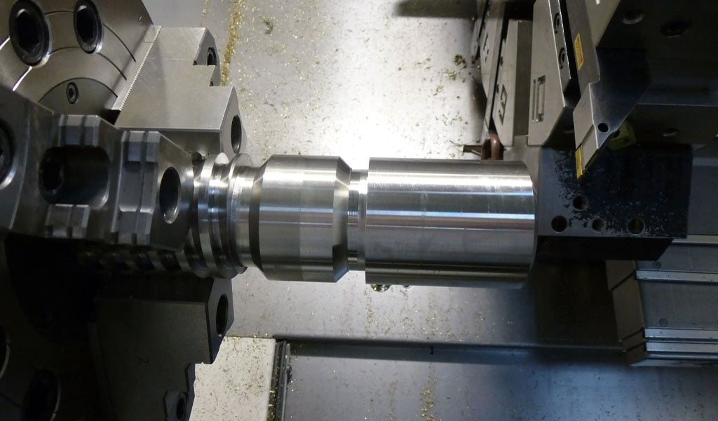
Machining involves single-point threading or thread milling, with tools ground to match the flank angles. Tolerances, per standards like DIN 513, ensure fitment, often verified via three-wire methods or optical comparators.
Conceptual Calculator Framework
A buttress thread calculator simplifies design by automating the above steps. Inputs include:
- Standard (e.g., DIN 513, DIN 2781)
- Nominal diameter
- Pitch
- External/Internal thread selection
Outputs provide:
- Major, minor, and pitch diameters
- Thread height
- Suggested wire sizes for measurement
Such a tool, implemented in software like Excel or Python, enhances precision and efficiency in engineering workflows.
Conclusion
Buttress threads, with their metric dimensions and unique angles, offer a robust solution for unidirectional load applications. Standards like DIN 513 and DIN 2781 provide a framework for their design, supported by detailed charts and calculative methods. This article has elucidated their geometry, standards, and practical utility, equipping readers with the knowledge to leverage these threads effectively in mechanical systems.


The Detail Of BE-CU Cnc Machining Shop
BE-CU.COM – As an accomplished CNC machining Service Manufacturer and CNC shop, BE-CU Prototype has been specialized in OEM CNC lathing, custom CNC machining parts production and rapid CNC machining services China for over 35 years and always maintaining the highest standard in delivery speed and reliable quality of precision CNC manufacturing components. With the help of high-level technology and efficient equipment, as well as rigorous attitude, BE-CU passed the ISO9001:2015 quality certification, which supports the long-term development of CNC milling services, CNC turning services, CNC milling-turning, CNC drilling services, 3/4/5 axis machining, gear machining services, CNC machining China custom parts and service, small parts machining, etc.Our CNC machining products can be utilized in a broad range of industries. Contact us for email: [email protected]

-

3-Way Centrifugal Compressor Closed Impeller By 5 Axis Machining
-

3/4/5 Axis Precision Milling Custom Vehicle Parts
-

3D Flexible Welding Platform By Large Machining
-

3D Printed Inconel Exhaust Manifold
-

3D Printing And CNC Machining Custom Black PPS Valve
-

3D Printing Full Transparent Acrylic Lampshade Model
-

4 Axis CNC Machining Titanium Grade 5 Mobile Phone Buttons
-

4 Axis Machining Highly Transparent Acrylic LED Tunnel Light Lens