
The face width of a gear refers to the width of the tooth-bearing surface along the axis of rotation. It plays a crucial role in determining the load-carrying capacity and overall performance of the gear. The face width is an important parameter in the design and analysis of gears, as it directly influences the gear’s strength, load distribution, and efficiency.
Calculating the face width of a gear involves understanding various parameters, including gear geometry, material properties, load requirements, and design standards. This article provides a comprehensive overview of the methods used to calculate the face width of gears, the factors that influence this calculation, and its significance in gear design.
Basic Concepts of Gear Geometry
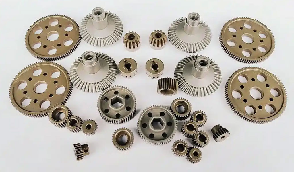
Before delving into the calculation of face width, it is essential to understand some basic concepts related to gear geometry. Gears are mechanical components used to transmit motion and torque between machine parts through meshing teeth.
They come in a variety of types, including spur gears, helical gears, bevel gears, and planetary gears, each with different design considerations.The key components of a gear that are relevant to face width calculation include:
- Pitch Diameter (D): The diameter of the pitch circle, which is the imaginary circle where the teeth of two meshing gears come into contact.
- Module (m): A metric unit used to describe the size of the teeth. The module is defined as the ratio of the pitch diameter to the number of teeth. It is used primarily in metric systems.
- Pressure Angle (ϕ): The angle between the line of action (the line along which the force is transmitted) and the line perpendicular to the pitch circle. The pressure angle affects the strength and efficiency of the gear.
- Number of Teeth (Z): The number of teeth on a gear, which influences its size, speed, and load capacity.
The face width is closely related to the amount of load a gear can transmit. A wider face allows for greater load distribution across the teeth, improving the gear’s strength and performance. However, a larger face width also increases the complexity and cost of manufacturing the gear.
Factors Influencing Face Width Calculation
Several factors influence the determination of face width, including:
- Load Carrying Capacity: The primary role of face width is to carry the load. A wider face width helps distribute the load across more teeth, reducing the stress on each individual tooth and improving the overall performance of the gear.
- Gear Type: The type of gear (e.g., spur, helical, bevel, etc.) has a direct impact on the face width calculation. For example, helical gears require slightly wider face widths due to the increased axial forces associated with their tooth geometry.
- Material Strength: The material used to manufacture the gear influences its ability to withstand forces. Stronger materials may allow for narrower face widths while still maintaining performance standards, while weaker materials may necessitate wider face widths.
- Contact Ratio: The contact ratio refers to the number of teeth in contact at any given time during the gear’s operation. A higher contact ratio usually leads to a wider face width, as more teeth are involved in load transmission.
- Speed and Torque Requirements: High-speed applications may require wider face widths to reduce wear and tear on the gear teeth, while low-speed, high-torque applications often benefit from increased face widths to handle higher loads.
- Manufacturing Constraints: The constraints imposed by manufacturing processes, such as casting, forging, or machining, may influence the feasible range for face widths. Larger face widths often require more intricate manufacturing techniques.
Calculating Face Width Based on Gear Load
To calculate the face width of a gear based on the load requirements, engineers typically use established formulas and design guidelines. One such approach is the calculation based on the gear’s load-carrying capacity, which can be derived from the basic gear equations.
A common formula for determining the face width based on the tangential load FtF_tFt is as follows:Ft=(2*T)/dp
Where:
- T is the torque transmitted by the gear
- dp is the pitch diameter of the gear (in meters or inches)
The face width bbb is then determined based on the gear’s load-carrying capacity and the pressure angle ϕ. A general equation used for this calculation is:b=Ft/σ
Where:
- σ is the allowable stress on the gear material
- Ft is the tangential load on the gear
Empirical Methods for Face Width Calculation
In practice, gear designers often rely on empirical formulas and design codes to determine the appropriate face width for a given application. One widely used standard is the AGMA (American Gear Manufacturers Association) 2001-A01, which provides guidelines for gear design based on load and material properties. The standard recommends calculating the face width based on a balance of strength and durability requirements.
The AGMA 2001-A01 standard suggests a range of face widths based on the number of teeth, gear size, and material strength. It provides designers with an acceptable range for face widths, considering factors such as gear type, load distribution, and operating conditions.
The formula provided by AGMA for calculating face width based on gear strength is:b=(C*P*Z0.33)/S
Where:
- C is a constant based on the gear type and application (spur, helical, etc.)
- P is the pitch of the gear
- Z is the number of teeth on the gear
- S is the material strength
This equation provides a balance between the strength of the gear material and the operating conditions, ensuring that the face width is optimized for load-bearing capacity.
Determining Face Width for Different Gear Types
- Spur Gears: Spur gears are the most common type of gears and have teeth that are straight and parallel to the axis of rotation. The face width for spur gears is typically calculated based on the load-carrying capacity and the gear’s material strength. As spur gears primarily experience radial forces, the face width does not need to be excessively large. However, it should still be sufficient to ensure adequate strength and durability.
- Helical Gears: Helical gears have teeth that are cut at an angle to the axis of rotation, which causes them to generate both radial and axial forces. The face width of helical gears is generally larger than that of spur gears to accommodate the additional axial forces. When designing helical gears, it is essential to factor in the axial load and the additional force distribution across the tooth surface.
- Bevel Gears: Bevel gears are used to transmit motion between intersecting shafts, typically at a 90-degree angle. The face width of bevel gears is influenced by the bevel angle and the load distribution across the teeth. In these gears, the face width is usually wider at the larger diameter and tapers to a narrower dimension toward the smaller diameter.
- Worm Gears: Worm gears, which involve a gear meshing with a worm (a type of screw), typically have a relatively narrow face width compared to other gear types. The face width calculation for worm gears takes into account the special geometry of the worm thread and the load capacity of the gear.
- Planetary Gears: In planetary gear systems, multiple gears mesh with a central sun gear. The face width calculation for planetary gears is complex, as it involves multiple stages and load distributions. The face width for planetary gears is typically optimized based on the overall load-sharing between the sun, planet, and ring gears.
Practical Considerations in Face Width Calculation
While the mathematical calculations and empirical formulas provide a strong foundation for determining face width, engineers must also consider practical factors during the design process. These considerations include:
- Wear and Tear: The face width must be large enough to distribute the load evenly across the teeth, reducing the risk of premature wear. Narrow face widths can lead to concentrated loads, increasing the risk of tooth wear and failure.
- Efficiency: A wider face width may result in more contact area, which can increase friction and reduce efficiency. Designers must strike a balance between face width and efficiency, optimizing the gear’s performance.
- Manufacturing Constraints: The cost and complexity of manufacturing gears with larger face widths must also be considered. Larger face widths may require more precise machining, which can increase production costs and lead times.
- Noise and Vibration: Gears with improper face widths may cause excessive noise and vibration during operation. Ensuring that the face width is optimized for the load and operating conditions helps reduce these issues.
Conclusion
The face width of a gear is a critical parameter that influences the gear’s load-carrying capacity, strength, and overall performance. Calculating the appropriate face width requires careful consideration of various factors, including the gear’s type, material, operating conditions, and load requirements. Using established design codes and formulas, engineers can determine the optimal face width for a given gear design, ensuring that it meets the performance, durability, and efficiency requirements of the application. By balancing these factors, gear designers can create gears that operate smoothly, with minimal wear and high load-bearing capabilities.


The Detail Of BE-CU Cnc Machining Shop
BE-CU.COM – As an accomplished CNC machining Service Manufacturer and CNC shop, BE-CU Prototype has been specialized in OEM CNC lathing, custom CNC machining parts production and rapid CNC machining services China for over 35 years and always maintaining the highest standard in delivery speed and reliable quality of precision CNC manufacturing components. With the help of high-level technology and efficient equipment, as well as rigorous attitude, BE-CU passed the ISO9001:2015 quality certification, which supports the long-term development of CNC milling services, CNC turning services, CNC milling-turning, CNC drilling services, 3/4/5 axis machining, gear machining services, CNC machining China custom parts and service, small parts machining, etc.Our CNC machining products can be utilized in a broad range of industries. Contact us for email: [email protected]

-

3-Way Centrifugal Compressor Closed Impeller By 5 Axis Machining
-

3/4/5 Axis Precision Milling Custom Vehicle Parts
-

3D Flexible Welding Platform By Large Machining
-

3D Printed Inconel Exhaust Manifold
-

3D Printing And CNC Machining Custom Black PPS Valve
-

3D Printing Full Transparent Acrylic Lampshade Model
-

4 Axis CNC Machining Titanium Grade 5 Mobile Phone Buttons
-

4 Axis Machining Highly Transparent Acrylic LED Tunnel Light Lens