
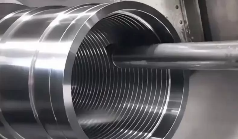
Numerical Control (NC) cutting processes, including thread cutting, use computer-controlled machines to precisely control the movement of cutting tools or workpieces. In the context of thread cutting, this involves creating threads on a cylindrical or conical surface. There are several methods to perform numerical control thread cutting, with the most common being lathe threading and CNC (Computer Numerical Control) milling.
Thread CNC Machining Process
Here’s an overview of the process:
Design and Programming:
The first step is to design the thread, specifying parameters such as thread pitch, major diameter, and minor diameter.
Using CAM (Computer-Aided Manufacturing) software, you create a CNC program that defines the toolpath and cutting parameters required to produce the thread.
This program includes commands for tool movement, spindle speed, and feed rate.
Machine Setup:
Secure the workpiece in the lathe or CNC milling machine. Ensure it is properly centered and aligned with the machine’s axis.
Tool Selection:
Choose the appropriate cutting tool for the thread type and material being machined. Common tools include threading inserts, taps, or thread mills.
Tool Positioning:
Bring the tool into position, aligning it with the starting point of the thread. This positioning is critical for accurate thread cutting.
Tool Engagement:
Gradually engage the tool with the workpiece, typically by feeding it along the axis while simultaneously rotating the workpiece (in the case of lathe threading) or moving the tool along a defined path (in the case of CNC milling).
Cutting Parameters:
Control parameters such as spindle speed and feed rate are crucial. These values depend on factors like material type, tool geometry, and thread specifications. Using the wrong parameters can lead to tool wear, poor thread quality, or even tool breakage.
Continuous Monitoring:
Throughout the thread cutting process, operators or CNC systems monitor the machining to ensure the thread dimensions and surface finish meet the specified requirements.
Thread Completion:
The machine continues to cut the thread until it reaches the desired length or depth. It is essential to stop the process precisely to avoid overshooting the thread dimensions.
Thread Inspection:
After the cutting is complete, the thread may undergo inspection using gauges and measuring tools to verify its accuracy and conformity to design specifications.
Finishing Operations:
Depending on the application and thread requirements, additional operations such as deburring, chamfering, or surface treatment may be performed.
Case Studies Of Thread Numerical Control Cutting Process
It is very important for users to use indexable thread turning tool for threading in CNC lathes and machining centers. The correct and reasonable selection of thread cutting technology is very important.
The thread cutting process depends on the structure of the machined parts and the CNC machine tool used. Generally speaking, using the right cutting edge to process right-handed threads and using the left cutting edge to process left-handed threads has the advantage of stable support of the blade. Of course, in general, the opposite method can also be applied.
Consistent in order to avoid excessive wear on one side of the blade and shortening of tool life as much as possible.
d2――Pitch diameter A――The blade inclination angle is usually determined by the shim of the indexable thread turning tool. The standard tool is +, but for the internal thread tools with diameters of 16mm and 020mm, there is no shim due to the small space. , So it cannot be processed when the blade inclination is greater than +2°.
The feed method of thread turning is determined by the cutting machine, workpiece material, insert geometry and the pitch of the thread being machined. There are usually the following four feed methods: *Commonly used cutting method, the left and right sides of the turning tool are cut at the same time , The axial cutting component force is offset to some extent, which partially overcomes the phenomenon of turning tool deviation caused by the axial cutting component force. The two sides wear uniformly, which can ensure the clear tooth shape, but there are problems such as poor chip evacuation, poor heat dissipation, and concentrated force. It is suitable for cutting threads with a pitch of less than 1.5mm. D single-side feed cutters feed at an angle with the radial direction. The chips are rolled away from the blade to form strips, which have better heat dissipation. The disadvantage is that the other edge is hardened due to the non-cutting of the friction part. D single-sided infeed direction of 30° angle infeed cutting. The cutting edge cuts on both sides to form rolled chips, smooth chip removal, good heat dissipation, and low thread surface roughness value. Generally speaking, this is the best method for turning stainless steel, alloy steel and carbon steel. About 90% of threaded materials use this method. It is best to use this method for thread processing on a CNC lathe. Generally, a fixed cycle can be called and the programming is simple.
The left and right side feeds alternately cutting, that is, each time the radial feeds, move a certain distance laterally to the left or right, so that only one side of the turning tool participates in the cutting. This method is generally used for general-purpose lathes and thread processing with a medium distance of more than 3mm, and programming on CNC lathes is more complicated.
Thread milling is mainly used for CNC boring and milling machine tools such as machining centers. Generally, small-diameter internal threads (20mm) can be processed by tapping. However, for the processing of large-diameter internal threads and external threads, there are many problems with tapping and sleeve threads. Therefore, medium grain iron cutting is the best processing. means.
Thread milling is different from thread turning plus X. This is because the pattern CNC milling is mainly realized through the three-axis linkage and helical interpolation processing of the machine tool, that is, while the two-axis arc sensitive cutting is processed, the first Three-axis linear feed motion. The axial movement distance is milled. It is a single-edge milling process. Therefore, the best way to feed is to use the radial direct feed cutting method, so that the two cutting edges cut at the same time, and the force is more uniform. , Which can ensure the accuracy of the thread, and the CNC programming is relatively simple.
The Choice Of Thread Turning And Milling Cutting
The choice of thread cutting parameters (cutting speed, back-cutting amount, number of passes) is determined by the material of the tool and the part. The cutting speed of thread turning is generally 25% ~50% lower than that of ordinary turning. The selection of the amount of backing of the thread and the number of passes are also particularly important. Whether the D value is correct or not is directly related to whether the medium pattern is qualified or not. The amount directly affects the size of the cutting force. The amount of the back of the centipede needs to follow the principle of decreasing, that is, the amount of the back of the back of the knife must be less than the amount of the previous one, and the value of the minimum back of the knife shall not be less than. 5 stomach. The following two tables provide the metric internal and external media pattern backing values. This table is also suitable for thread milling.
Table 1 ISO Metric Pattern Back Knife Setting Value (External Thread) (mm) Pitch Back Knife Cutting Times Flavored Back Knife Quantity Cutting Times Table 2 ISO Metric Pattern Back Knife Setting Value (Internal Thread) Cadmium Back Knife Cutting Times For CNC boring and milling machine tools, although thread milling is realized by three-axis linkage spiral interpolation processing, which is different from thread turning, the choice of cutting quantity can still be used by turning media. The relevant cutting parameters of the pattern. Because the thread milling is made by single-edge cutting, the cutting speed should be half that of turning, and the amount of back-cutting can still be selected according to turning.
Thread Turning And Milling
CNC program preparation For CNC lathes, the general standard thread turning programming instructions are G33 (fixed pitch cutting), G34 (variable pitch butterfly cutting with increasing pitch), G35 (variable pitch with decreasing pitch Thread cutting). The medium distance is specified by / and person ruler, where K /, A: correspond to the X and Z axes respectively. However, general CNC systems and machine tool manufacturers provide thread turning canned cycles for users to use, and only need to input the necessary parameters. H. When processing special butterfly patterns, it is necessary to use the G command and the programming method of calculating the coordinate points by yourself.
The programming of thread milling processing is different from that of CNC turning. G02 and G03 arc interpolation commands are mainly used, that is, the third axis linear interpolation is added while the two-axis arc interpolation is added to form a spiral interpolation movement. The following is the ordinary internal thread M30X 2, deep 14mm CNC milling processing program , Take the knife back to 1.2mm, adopt the radial direct cutting method.
F200 takes edge compensation, radial feed to the position of the back-grabbing tool. In centuries cutting, it is often due to the correctness of the selection of tools (including inserts, shim and arbor, etc.), feed method, cutting amount, etc. This may be due to excessive extension of parts or tools, poor rigidity, excessive cutting of the center of the tool, and incorrect selection of cutting amount, blades, and stings And other factors. It is possible to increase or decrease the cutting speed, shorten the outer elongation of the tool, adjust the center height or feed method, adopt side feed or radial feed, adequate cooling, increase the number of passes and other solutions.
Fast tool wear and short tool life are caused by too fast cutting speed, insufficient cooling, too many cutting times, and wrong blade brand. It can be used to reduce the cutting speed, fully cooling, reduce the number of cutting, choose the hardness of the wear-resistant blade D with good toughness, change the cutting angle, increase the cooling, increase the cutting speed, reduce the amount of back knife, and adjust the center frame.
In the traditional CNC machining process, the bottom surface is scribed and planed first, and then processed on the T611 boring machine. During processing, each piece needs to be corrected, which is troublesome in clamping, time-consuming and labor-intensive, and low efficiency.
The processing capacity is insufficient. Therefore, we designed a special tooling fixture for turning and boring to produce a bearing bracket (H7rr35 with a center height of 257s), which is the main size of the workpiece. Based on this, the design of tooling fixtures is as shown. The jig is used on the CW6263 lathe.
The clamp is composed of a main body 3 and a three-jaw self-centering chuck 4. Remove one claw of the three-jaw self-centering chuck. The left end of the main body 3 is connected with the chuck and fastened with bolt 1. The A side table is placed on the positioning surface of the bearing bracket. The main body has two notches for the free movement of the claws. s First, ensure the center of the bearing bracket 5, and then use the three-claw self-selection due to improper selection, to change the feed method and cut corners.
The built-up edge on the cutting edge increases the cutting speed and increases the cooling. The coated carbide inserts are used for cutting with an improved side feed.
Excessive plastic deformation of the tool is due to poor cooling, too high cutting speed, the wrong blade grade, and the amount of back-grabbing each time is too large. Should reduce the amount of back-grabbing, increase cooling, reduce cutting speed, increase cutting times, use high hardness, wear-resistant hard alloy or Xu layer blades.
If there is a burr on the thread, the cutting speed should be increased. Use the automatic centering principle of the cutting centering chuck 4 to clamp the workpiece for processing.
Then Tighten The Chuck To Clamp The Workpiece
The use of car instead of collision fully meets the design requirements of the bearing bracket, guarantees dimensional accuracy and position accuracy, and saves workpiece scribing and correction, guarantees quality, and improves work efficiency by 1.8 times compared with boring.
Bearing brackets with different center heights can be adjusted by adding pad irons, but they need to be fastened by bolts.
Before use, balance adjustment is required to avoid the influence of centrifugal force on the quality of the workpiece and the pressure plate on the equipment.
Numerical control cutting processes offer high precision and repeatability, making them ideal for producing threads in various materials and applications, including aerospace, automotive, and manufacturing industries. CNC technology has significantly improved the efficiency and accuracy of thread cutting operations, reducing the need for manual labor and minimizing errors.
The Detail Of BE-CU Die Casting Company
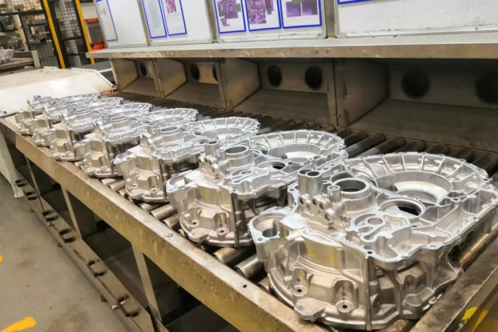
If you are looking for dependable volume manufacturing metal parts supplier with High pressure die casting service who offers you competitive price, good service and quality for aluminium die casting, zinc, or magnesium die casting, then BE-CU Prototype are surely a partner you are looking for to fulfill all your die casting needs. With quality service and state of art technology, BE-CU indeed claim in providing quality pressure die casting including aluminum/zamak/magnesium alloy castings to our customers all over the world.
To work with us,be-cu don’t just stop at taking your order and delivering your die casting products. be-cu are there for you at every step right from your preferred selection of aluminum die casting, Zamak die casting (Zamak 2, Zamak 3, Zamak 5, Zamak 8) or magnesium die casting products and services to post-order phase. In brief, once you become our customer, be-cu are with you every step on the way.
-
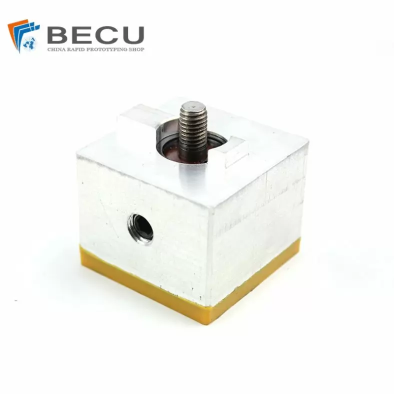
CNC Machining Gas Stove Bottom Joint
-
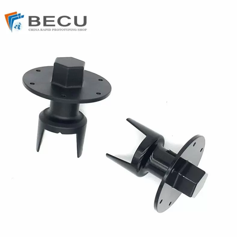
Gravity Die Casting Custom Street Light Heat Sink
-
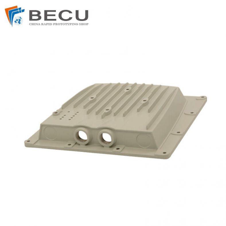
Die Casting LED Canopy Lights Heatsink For Gas Station
-
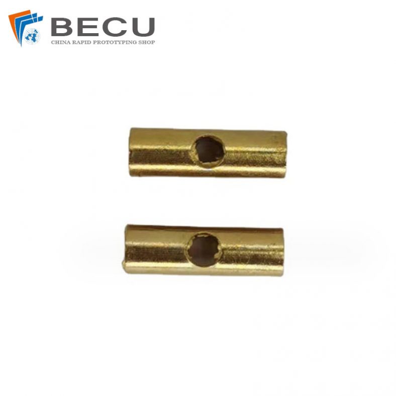
Zinc Die Casting PA10 Transformer Connector Terminal
-
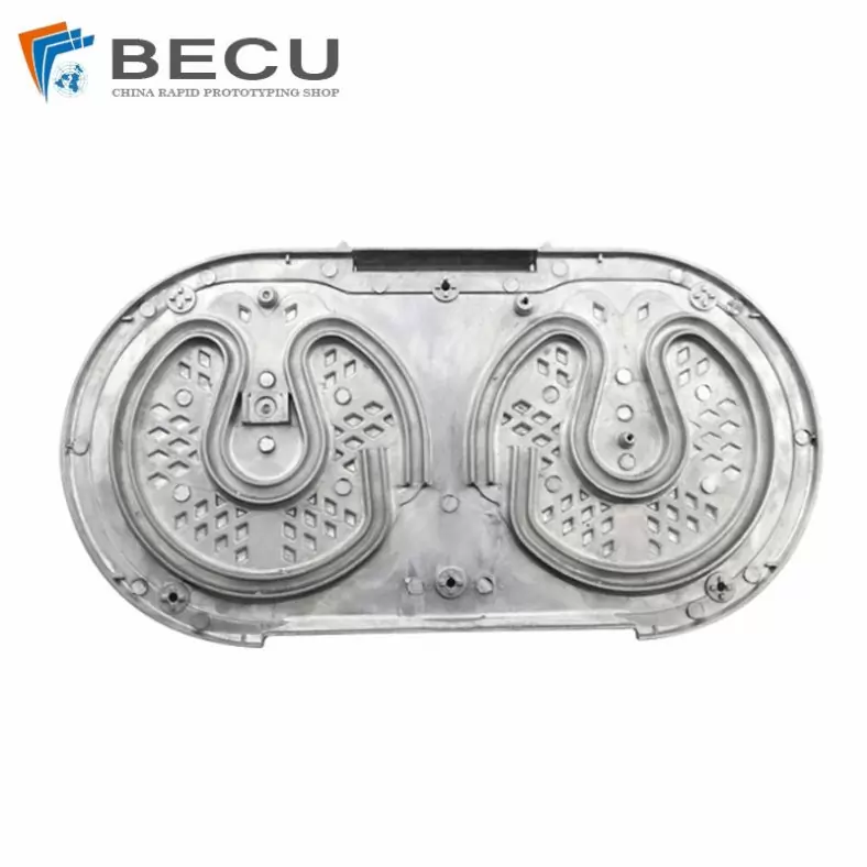
Die Casting Aluminium Cookware Chassis
-
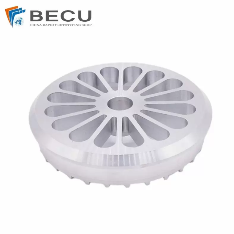
Die Casting Wheels With Aluminum Alloy 5 Axis CNC Machining
-
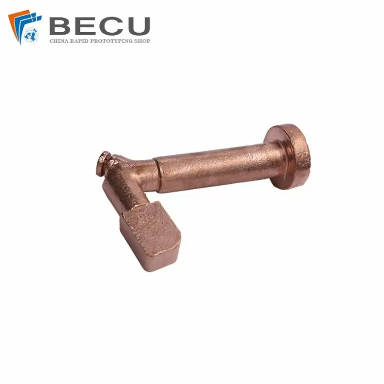
Precision Machined Copper Die Casting Parts
-
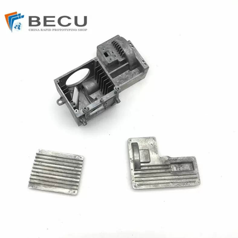
Professional Small Baler Aluminum Alloy Die-casting Mold Production
-
China Die Casting Factory Manufactures Surface Sprayed Aluminum Valve Body
-
Extrusion Die-casting Polyurethane-Coated Aluminum Alloy Profiles
-
Custom Precision Aluminum Die Cast Brackets and Finishes
-
Extrusion Die-casting Magnesium Alloy Heat Sink Shell