
Control valves play a crucial role in regulating the flow of fluids in various industrial processes, from oil refineries to chemical plants and power generation facilities. However, like any mechanical component, control valves are susceptible to faults and degradation over time, which can impact process efficiency, safety, and overall productivity. To mitigate these issues, it is essential for maintenance professionals to understand the common faults that can affect control valves and implement effective maintenance strategies. In this comprehensive guide, we will delve into the various types of control valve faults, their causes, symptoms, and the best practices for maintenance and troubleshooting.
Types of Control Valve Faults
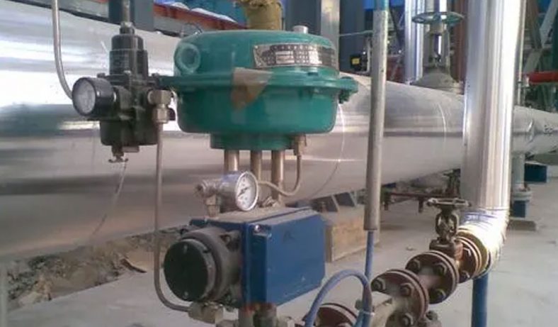
Regulating valve, also known as control valve, in the field of industrial automation process control, by receiving the control signal output by the regulating control unit, using power operation to change the final control element of the process parameters such as medium flow, pressure, temperature, and liquid level. The regulating valve is suitable for air, water, steam, various corrosive media, mud, oil and other media. Commonly used classification of control valves: pneumatic control valve, electric control valve, hydraulic control valve, self-operated control valve.
- Sticking or Binding: Sticking or binding of control valves occurs when the valve fails to move freely within its housing, leading to erratic or incomplete control of fluid flow. This can be caused by factors such as corrosion, dirt accumulation, or insufficient lubrication. Symptoms include inconsistent process control, increased friction, and abnormal valve operation noises.
- Seat Leakage: Seat leakage refers to the unwanted flow of fluid through the closed valve seat, resulting in loss of process control and potential safety hazards. Common causes of seat leakage include wear and tear of valve components, improper installation, or damage to sealing surfaces. Symptoms may include visible leaks, reduced system pressure, and fluctuations in flow rates.
- Actuator Malfunction: The actuator is responsible for moving the valve stem in response to control signals, and any malfunction in this component can impair valve performance. Actuator faults can stem from electrical issues, mechanical failures, or inadequate air supply. Symptoms may include slow response times, erratic valve positioning, or complete loss of control.
- Corrosion and Erosion: Corrosion and erosion can degrade valve components over time, compromising their structural integrity and functionality. Factors such as exposure to corrosive fluids, high-velocity flow, or abrasive particles can accelerate the degradation process. Symptoms of corrosion and erosion include pitting, surface roughness, and deterioration of material properties.
- Cavitation and Flashing: Cavitation occurs when vapor bubbles form and collapse within the valve due to pressure fluctuations, leading to erosion of valve internals and reduced performance. Flashing occurs when a high-pressure liquid undergoes rapid depressurization, resulting in vaporization and potential damage to the valve trim. Symptoms include noise, vibration, and material erosion in high-velocity flow areas.
Maintenance Strategies
- Routine Inspection and Testing: Regular inspection and testing of control valves are essential for detecting potential faults and ensuring optimal performance. This includes visual inspection of valve components, functional testing of actuators, and verification of control signals. Scheduled maintenance intervals should be established based on operating conditions and manufacturer recommendations.
- Lubrication and Cleaning: Proper lubrication of valve components helps reduce friction, prevent sticking, and prolong service life. Cleaning of valve internals is also important to remove debris, scale, or corrosion products that can impair performance. Maintenance personnel should use compatible lubricants and cleaning agents recommended by the valve manufacturer.
- Seal Replacement: Periodic replacement of valve seals and gaskets is necessary to prevent seat leakage and ensure tight shut-off. Seals may degrade over time due to exposure to harsh operating conditions or chemical attack. Maintenance schedules should include provisions for seal replacement based on service life expectancy and performance monitoring.
- Trim Repair or Replacement: Valve trim components such as plugs, seats, and stems may require repair or replacement due to wear, erosion, or damage. Maintenance personnel should assess trim condition during inspections and address any signs of degradation promptly to avoid performance issues. Replacement parts should meet OEM specifications and quality standards.
- Calibration and Adjustment: Calibration of control valves involves verifying their response to control signals and adjusting settings as needed to achieve the desired performance. This may include adjusting actuator pressure, stroke limits, or positioner settings to optimize control loop performance. Regular calibration ensures accurate process control and prevents deviations from setpoint values.
Troubleshooting Techniques:
- Performance Monitoring: Continuous monitoring of valve performance parameters such as flow rates, pressure drops, and control loop response times can help identify potential faults or deviations from normal operation. Trend analysis of process data can reveal patterns indicative of valve degradation or malfunction, prompting timely intervention.
- Diagnostic Testing: Diagnostic testing techniques such as valve signature analysis, leak detection, and functional testing can provide valuable insights into the health status of control valves. These tests involve simulating various operating conditions and observing valve response to identify any abnormalities or performance issues.
- Root Cause Analysis: In cases of recurring or persistent valve faults, conducting a root cause analysis is essential to identify the underlying factors contributing to the problem. This may involve examining maintenance records, conducting failure mode analysis, or performing metallurgical investigations to pinpoint the root cause and implement corrective actions.
Fault Summary
Air supply system failure
1.The instrument wind line is blocked
Because the ball valve has a throttling effect at the end of the instrument branch wind line, the stolen goods in the wind line are easy to accumulate and block. As a result, the instrument wind pressure is too low, the regulating valve cannot be fully opened and closed, or even the regulating valve does not operate.
2.Air filter pressure reducing valve failure
The air filter pressure reducing valve is used for a long time with too much stolen goods, the pressure reducing valve is leaking, and the output pressure of the pressure reducing valve is set to be too low, so that the output instrument wind pressure is less than the specified pressure. As a result, the regulating valve is slow to move, and cannot be fully opened or closed or even does not move.
3.Copper pipe connection failure
The copper pipe is aging and leaks, the joint connection is loose or the copper pipe is blocked by stolen goods, so that the instrument signal wind pressure is low, which causes the regulating valve to not operate and cannot be fully opened and closed. The manual state of the valve position is unstable and the adjustment oscillation occurs.
4.Failure of instrument air system
The air compressor station is abnormal, the purification wind tank of the device is abnormal, the wind line is frozen if the water is not cut in time, the instrument wind line is leaked or blocked by stolen goods, causing the device’s instrument wind pressure to be too low or even no wind.
5.The valve of the instrument air branch line is not opened, causing the regulating valve to not operate
This phenomenon often occurs during the overhaul of the device and during the drive after the renovation.
6.Power System Failure
The power cord terminal is loose, short-circuited, dropped off, or connected to the wrong polarity.
Due to on-site vibration, weak wiring, loose wiring or too much dust, poor contact, sometimes no signal from the control room to the site, resulting in chaotic control valve action and adjustment oscillation.
Due to wiring errors, water or moisture in the equipment and other reasons, the power cord is short-circuited, so that the signal received by the regulating valve is lower than the signal of the regulator, causing the regulating valve to not be fully opened and closed.
Malfunction in the middle joint of the power cord or the injured part
The power cord is subjected to environmental vibration, external force pulling, insulation tape failure, insulation performance degradation, and the joints entering water and high temperature baking. The power cord joints are loose or seem to be broken, and the power cords are short-circuited or short-circuited to the ground. The power cord is broken. As a result, the action of the regulating valve is discontinuous, and it cannot be fully opened or closed, and does not move. During the maintenance process, the middle connector of the power cord was connected reversely, causing the regulating valve to fail to operate.
The regulating valve is not controlled by the regulator.
During the overhaul of the device and the drive after the renovation, the power cord is connected incorrectly or the configuration in the control room is incorrect, causing the regulating valve to not be controlled by the regulator.
Electrical Converter Failure
1. Inaccurate zero point and range
The zero point and range of the converter’s output signal are inaccurate due to inaccurate installation and debugging, on-site vibration, temperature changes, etc. As a result, the regulating valve cannot be fully opened and closed, and the leakage is large and limited.
During the on-site adjustment of the converter, the correct indication of the converter signal meter should be ensured first. The small signal meter should be maintained normally.
2. The orifice is blocked
The instrument wind clogging the throttle orifice. Resulting in the control valve not operating.
3. The output is not linear
The output of the converter is not linear due to the aging of the coils and components in the converter or the influence of on-site vibration and ambient temperature. As a result, the required value cannot be reached during the adjustment of the zero point and range, and the action of the regulating valve is not linear. Fully open and close.
Valve positioner failure
1 Electric valve positioner
1. Inaccurate zero point and range
Due to inaccurate debugging during the installation process of the positioner, on-site vibration, temperature changes, changes in the valve stem stroke of the control valve, changes in the position of the feedback lever, etc., the minimum opening and maximum opening of the control valve are inconsistent with the signal from the control room. As a result, the signal output by the valve positioner cannot make the regulating valve fully open and close, resulting in large leakage and limited quantities.
In the on-site adjustment of the positioner, it is necessary to first ensure that the regulating valve operates well, the feedback system is installed firmly and operates well, and then the standard signal is used to adjust. Make the stroke of the regulating valve consistent with the control signal.
2. The orifice is blocked
The stolen goods block the orifice. The positioner has no output signal, causing the regulating valve to not operate.
3. There is stolen goods between the nozzle and baffle
Affected by the on-site environment, a layer of dust will adhere to the positioner after a period of use, which will affect the back pressure of the nozzle baffle, thereby affecting the output of the positioner. Cause the control valve to be unstable and oscillate.
4. Poor sealing
The various fastening nuts and sealing gaskets of the positioner that have been used for a long time are prone to loosening and aging, which will cause the positioner to leak air. So that the regulating valve cannot be fully opened and closed, the valve position is unstable, and regulation oscillation occurs.
5. Feedback lever failure
During long-term operation, the fastening nut of the feedback rod gradually loosens or even falls off, causing the feedback rod to become loose, skewed, jammed with the fixed parts, and fall off. It is difficult to stabilize the controlled parameters, especially in temperature control where the action of the regulating valve requires accurate temperature control.
6. The fixing nut is loose
If the fixing nut of the positioner is not installed firmly, it will become loose, which will cause the positioner to skew, affect the action of the feedback lever, and cause jamming. Make the control valve unstable and cause position limit and other phenomena.
The fastening screws of various springs in the positioner are loosened in a vibration environment, which changes the preload of the spring and affects the tension and state of the spring. The zero point range of the positioner is changed, the positioner is not linear, so that the regulating valve cannot be fully opened and closed, and the regulating valve action is not linear.
7. The position of the permanent magnet changes
Due to the external force, the positions of the two magnets are changed and the position of the magnetic field is changed. The force of the coil is unbalanced, and the output of the positioner is not linear, which makes the action of the regulating valve non-linear. The magnet attracts impurities such as iron pins, forming a jam and obstructing the movement of the baffle, making the output of the positioner inaccurate, so that the action of the regulating valve is inconsistent with the control signal.
2Smart locator
1. Feedback lever failure
The feedback rod tightening nut is loose or even falls off, causing the feedback rod to become loose, skewed, jammed with the fixed parts, and fall off. The control valve is slow to act, fluctuates frequently, and the control valve is limited or even out of control.
If the positioner is not firmly fixed, it will become skewed and loose, which will affect the movement of the feedback lever and cause the jamming phenomenon to limit the position of the regulating valve.
The limit spring on the feedback board falls off, or the feedback lever comes out of it, resulting in poor contact between the feedback lever and the feedback board, resulting in hysteresis, and frequent actions of the regulating valve. It is difficult to stabilize the controlled parameters, especially in temperature control where the action of the regulating valve requires accurate temperature control.
2. The positioner is not well adjusted
During the adjustment, the middle position is not found properly, the regulating valve is not fully opened and closed during manual output, and the air-on and air-off options are not equal. The regulating valve cannot be fully opened and closed, resulting in large leakage and position limitation.
3. Wrong adjustment method
Because the adjustment of the intelligent positioner is complicated, takes a long time, and requires multiple full openings and closings, which has large fluctuations in the process, the adjustment valve should be cut out during adjustment, especially when adjusting the temperature control valve must be offline Adjustment.
3 The control valve itself is faulty
1. The leakage problem of the regulating valve
The leakage of the regulating valve is large, and there is a gap between the valve core and the valve seat when the regulating valve is fully closed, resulting in a large flow of the medium when the valve is fully closed, and the controlled parameters are difficult to stabilize.
In the adjustment of the adjustment valve, improper adjustment of the adjustment valve stroke or prolonged use of the valve core causes the head of the valve core to wear and corrode. The valve stem is usually adjusted downward to reduce the gap to reduce leakage.
Corrosion of the medium around the valve core is relatively serious, and the valve core is scratched by welding slag, rust, slag, etc. in the medium. The valve core should be taken out for grinding, and in serious cases, the valve core should be replaced with a new one.
The valve seat is seriously corroded by the medium, or the welding slag, rust, slag and other scratches in the medium cause scars, and the seal between the valve seat and the valve body is damaged. The valve seat should be taken out for grinding, and the sealing gasket should be replaced. In serious cases, the valve should be replaced with a new one.
The valve is blocked by welding slag, rust, slag and other stolen materials, which makes the regulating valve unable to be fully closed. The regulating valve should be disassembled and cleaned. At the same time, observe whether the valve core and valve seat are scratched and worn.
The sealing gasket between the valve core and the seat of the sleeve valve is damaged, and the sealing ring of the butterfly valve is damaged, so that the throttle gap is relatively large when the regulating valve is fully closed.
2. Control valve packing failure
The friction between the valve stem and the packing makes it difficult for the control valve to move with small signals, and the large signal jumps and vibrates, resulting in large fluctuations in the control valve during the adjustment process, and the parameters are difficult to stabilize. When the friction is large, the control valve will move in one direction or even not move. Lubricating oil or grease should be added regularly in daily maintenance. Packing is seriously aging, and the packing should be replaced if the leakage is serious.
3. The connection problem between the valve stem and the connector
The valve stem and the connecting piece are loose or falling off. Due to on-site vibration or loosening of the fastening nut of the connecting piece, the valve stem is too low and the connecting part is too small. During operation, the valve stem and the actuator push rod are not synchronized or fall off. Affect the action of the regulating valve or even malfunction.
4. The valve seat is stuck or blocked by foreign matter
5. Failure of the regulating valve membrane head
The corrugated diaphragm of the regulating valve deteriorates after long-term use, the elasticity becomes smaller, the airtightness becomes worse, and even cracks and air leakage are serious. The elastic coefficient of the compression spring changes due to aging, and even breaks.
6. Setting of PID parameters in the control valve control system
Improper PID setting affects the action of the regulating valve and even causes the regulating valve to oscillate, which affects the service life of the valve.
7. Confirmation of process status
When the leakage of the regulating valve is large, confirm whether the auxiliary line valve is fully closed, and when the regulating valve is limited, confirm the opening degree of the valve before and after the regulating valve. When the controlled parameter changes frequently, confirm whether there are large fluctuations in the process flow.
8. Regulating valve maintenance problems
When repairing the fuel oil regulating valve of the heating furnace, it is best to cut the regulating valve out of the auxiliary line to prevent it from affecting production. If you do not cut out, you can open a little bit of the auxiliary line valve. During maintenance, make sure that the furnace does not turn off because the regulating valve is fully closed.
Maintenance Summary
1. The regulating valve does not move
Reason: There is no air source or the air source pressure is too low.
Measures: First, check whether the air source (instrument air) is unobstructed, and whether the air source pressure meets the requirements of the valve.
Reasons: There is a gas source, but there is no output signal gas pressure.
- Measure 1: For the electronically controlled intelligent regulating valve, check the power supply of the control signal line of the valve intelligent positioner, and use a digital multimeter to measure the control room to control whether the power signal DC4-20mA is normal. If it is abnormal or not, check the PLC system, wiring and other faults. If it is normal, the valve positioner should be replaced.
- Measure 2: For the mechanical controller or positioner, the mechanical pressure controller or positioner should be replaced.
- Measure 3: For the regulating valve of the mechanical controller, check whether the signal collection pipeline valve of the medium on the regulating valve installation pipeline is fully opened or leaks serious, and if there is any abnormality, it should be dealt with in time.
Reason: The output signal gas pressure is normal, but it still doesn’t work.
- Measure 1: Check whether the diaphragm of the pneumatic diaphragm actuator has serious air leakage. If it leaks, replace the diaphragm and related seals in time.
- Measure 2: If the diaphragm is intact and there is no air leakage, the main valve spool, bushing and valve seat should be stuck, and the main valve should be disassembled to check and clean up debris.
- Measure 3: The valve stem is severely bent and deformed. The main valve should be disassembled and inspected, and replaced according to the inspection.
- Measure 4: The signal gas source pipeline is leaking, check and deal with the leaks.
- Measure 5: The signal amplifier is faulty or improperly adjusted, and the main air source does not enter the diaphragm cavity through the amplifier, and the amplifier should be adjusted or replaced in time.
2. When the regulating valve is working, it produces regulation oscillation and control instability
Reason: The pressure of the air source has changed greatly or the filter and the pressure reducing valve are not working properly.
- Measure 1: Check the operating status of the compressed air system.
- Measure 2: Check and replace the filter or pressure reducing valve.
Reason: The air source pressure is stable, and the signal pressure is unstable.
- Measure 1: The electronically controlled intelligent positioner is faulty, and the positioning is initialized and calibrated. If it is not stable after calibration, the intelligent positioner should be replaced.
- Measure 2: If the intelligent positioner is still unstable after replacing the intelligent positioner, the PID# parameter should be tuned.
- Measure 3: For the mechanical controller or positioner, the mechanical controller or positioner should be replaced, and the controller should be adjusted.
- Measure 4: After replacing the mechanical controller or positioner, it is still unstable. Check and replace the signal air source amplifier and make adjustments.
Reasons: The air source and signal pressure are stable, but the control valve is still unstable.
- Measure 1: Check the air tightness of the pneumatic diaphragm actuator. Check carefully whether there is a slight air leakage in the drive push rod seal. If there is air leakage, disassemble and replace the seal; disassemble and check whether the diaphragm has scratches or punctures caused by slight air leakage. If there is a leak, replace the diaphragm.
- Measure 2: Check carefully whether there is a gap between the positioner and the main valve. Replace or tighten the relevant connections between the positioner and the main valve.
- Measure 3: Use soapy water to carefully check whether there is a slight air leak in the signal gas pipeline, and deal with it in time if it is found.
- Measure 4: The setting of the signal air source amplifier is unreasonable, adjust the balance screw of the signal air source amplifier.
- Measure 5: The resistance of the regulating valve movement mechanism (including the main valve and pneumatic diaphragm actuator) is too large, the main valve should be disassembled, and abnormal components should be checked and replaced, including the valve core, valve seat, valve stem, valve stem seal and drive push rod.
- Measure 6: Check whether the pressure balance spring in the pneumatic diaphragm actuator is damaged, check whether the spring has been fatigued and deformed, if there is an abnormality, replace the pressure balance spring.
3.The control valve action is slow
- Reason: There is sticky stuff in the valve body.Measures: Disassemble the main valve body and clean up the sticky substance in the valve body.
- Reasons: The stem packing has deteriorated and hardened or the graphite and asbestos packing lubricants are dry.Measures: Disassemble the main valve body and replace the stem packing.
- Reasons: If the packing is too tight, the frictional resistance will increase.Measure 1: After loosening the stem packing compression nut, reciprocate the main valve several times, and adjust the stem packing compression nut to a suitable torque.Measure 2: If measure 1 does not work, replace the stem packing and adjust the stem packing compression nut to a suitable torque.
- Reasons: The valve stem is not straight, resulting in high frictional resistance.Measures: Disassemble the main valve and replace the valve stem.
- Reasons: There is a slight air leakage in the diaphragm of the pneumatic diaphragm actuator or the signal air pipeline.Measures: Replace the diaphragm of the pneumatic diaphragm actuator, and deal with the leakage of the signal gas pipeline.
4. The regulating valve operates normally and the process control parameters are abnormal
- Reason: The valve core of the regulating valve has fallen off.Measures: Disassemble and inspect the main valve body of the regulating valve, and restore the spool to fall off according to the inspection.
- Reason: The connecting part of the valve core and the valve stem is relatively displaced, but not disconnected.Measures: Disassemble and inspect the main valve body of the regulating valve, and restore the position of the spool according to the inspection.
- Reason: The valve stem of the regulating valve is broken.Measures: Disassemble and check the main valve body of the regulating valve, and replace the valve stem.
- Reasons: There is dirt blockage in the valve core of the regulating valve.Measures: Disassemble and inspect the main valve body of the regulating valve, and clean up the dirt in the valve core.
- Reason: The other control parameters of the controlled medium system are not suitable.Measures: Adjust the system control parameters within the design requirements.
Conclusion
Effective maintenance of control valves is essential for ensuring reliable and efficient operation of industrial processes. By understanding the common faults that can affect control valves and implementing proactive maintenance strategies, maintenance professionals can minimize downtime, reduce maintenance costs, and enhance process safety and productivity. Adherence to best practices such as routine inspection, lubrication, seal replacement, and diagnostic testing will help optimize control valve performance and prolong service life, ultimately contributing to overall operational excellence.
The Detail Of BE-CU Die Casting Company
If you are looking for dependable volume manufacturing metal parts supplier with High pressure die casting service who offers you competitive price, good service and quality for aluminium die casting, zinc, or magnesium die casting, then BE-CU Prototype are surely a partner you are looking for to fulfill all your die casting needs. With quality service and state of art technology, BE-CU indeed claim in providing quality pressure die casting including aluminum/zamak/magnesium alloy castings to our customers all over the world.
To work with us,be-cu don’t just stop at taking your order and delivering your die casting products. be-cu are there for you at every step right from your preferred selection of aluminum die casting, Zamak die casting (Zamak 2, Zamak 3, Zamak 5, Zamak 8) or magnesium die casting products and services to post-order phase. In brief, once you become our customer, be-cu are with you every step on the way.
-
CNC Machining Gas Stove Bottom Joint
-
Gravity Die Casting Custom Street Light Heat Sink
-
Die Casting LED Canopy Lights Heatsink For Gas Station
-
Zinc Die Casting PA10 Transformer Connector Terminal
-
Die Casting Aluminium Cookware Chassis
-
Die Casting Wheels With Aluminum Alloy 5 Axis CNC Machining
-
Precision Machined Copper Die Casting Parts
-
Professional Small Baler Aluminum Alloy Die-casting Mold Production
-
China Die Casting Factory Manufactures Surface Sprayed Aluminum Valve Body
-
Extrusion Die-casting Polyurethane-Coated Aluminum Alloy Profiles
-
Custom Precision Aluminum Die Cast Brackets and Finishes
-
Extrusion Die-casting Magnesium Alloy Heat Sink Shell