
Designing assemblies for 3D printing requires a nuanced understanding of additive manufacturing principles, component relationships, and design for manufacturability. This article delves into the intricacies of creating functional and efficient assemblies for 3D printing, exploring design considerations, optimization techniques, material selection, and post-processing methods. By following the guidelines outlined here, designers can harness the full potential of 3D printing to produce innovative, high-quality assemblies.
Introduction to 3D Printing Assemblies
The world of manufacturing has undergone a revolution with the advent of 3D printing, also known as additive manufacturing.
This transformative technology has enabled the creation of complex and intricate objects, layer by layer, directly from digital designs. One of the most fascinating applications of 3D printing is in the realm of assemblies, where multiple components come together to form functional and intricate systems.
Designing assemblies for 3D printing presents a unique set of opportunities and challenges that require a deep understanding of both additive manufacturing principles and traditional design methodologies.
Defining 3D Printing and Its Benefits for Assembly Design
At its core, 3D printing is a manufacturing process that builds objects layer by layer, using various materials such as plastics, metals, ceramics, and even biological materials. Unlike traditional subtractive manufacturing methods that involve cutting away material from a solid block, 3D printing adds material precisely where it’s needed. This fundamental difference opens up new possibilities for designing and fabricating assemblies that were previously constrained by the limitations of traditional manufacturing techniques.
The benefits of 3D printing for assembly design are numerous and transformative:
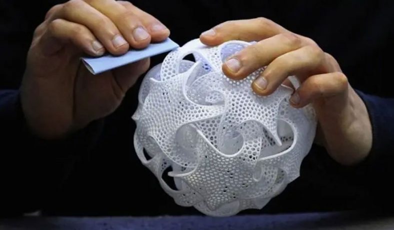
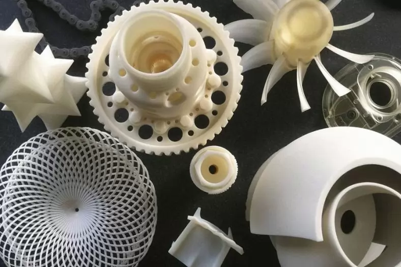
- Design Freedom: 3D printing allows for the creation of complex geometries that were previously impossible or economically impractical to manufacture. Intricate interlocking parts, hollow structures, and complex organic shapes can be easily realized through additive manufacturing.
- Customization: Assemblies can be tailored to specific requirements and user preferences. This level of customization is particularly advantageous in industries like healthcare, where patient-specific medical devices can be produced.
- Rapid Prototyping: Iterative design processes are facilitated by the quick turnaround time of 3D printing. Designers can rapidly produce prototypes, test them, and make modifications efficiently.
- Reduced Material Waste: Traditional manufacturing methods often generate significant material waste due to subtractive processes. 3D printing, on the other hand, generates minimal waste, as material is only deposited where needed.
- Complexity at No Extra Cost: Traditional manufacturing complexity is often associated with increased costs. In 3D printing, complexity doesn’t necessarily translate to higher expenses, making intricate designs more accessible.
- Assembly Consolidation: 3D printing enables the integration of multiple components into a single printed part, reducing the need for assembly and fasteners, which can simplify designs and reduce potential failure points.
Overview of Additive Manufacturing Processes
There are several different additive manufacturing processes, each with its own strengths and limitations. Some of the most common 3D printing technologies include:
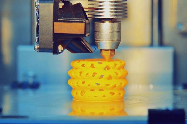
- Fused Deposition Modeling (FDM): FDM works by extruding melted thermoplastic materials through a nozzle, layer by layer, to build up the desired object. It’s widely used for rapid prototyping and functional parts due to its accessibility and affordability.
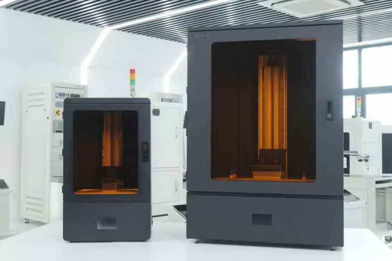
- Stereolithography (SLA): SLA uses a liquid resin that is solidified using a UV laser. It produces high-resolution parts with smooth surfaces, making it suitable for detailed assemblies.
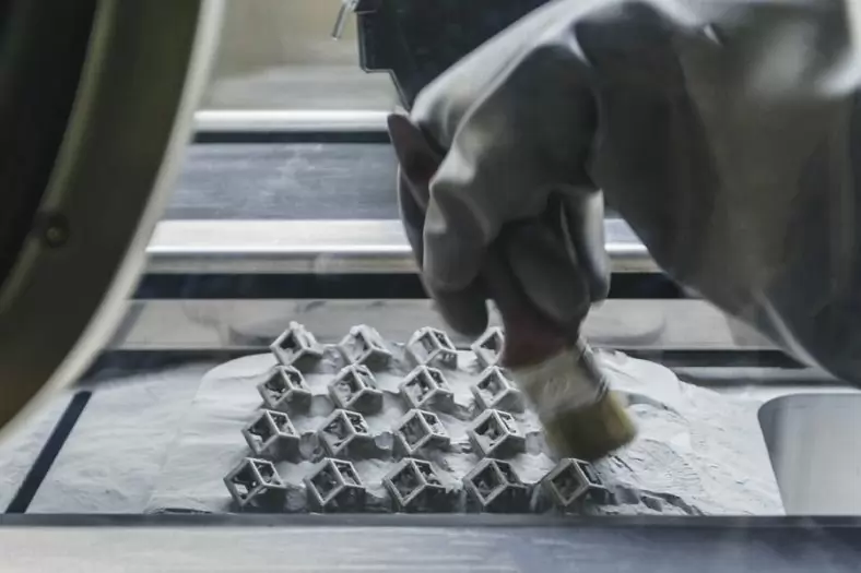
- Selective Laser Sintering (SLS): SLS fuses powdered materials, such as plastics or metals, layer by layer using a high-power laser. It’s known for its ability to create functional, strong, and intricate parts.
- Direct Metal Laser Sintering (DMLS): DMLS employs a laser to fuse metal powders, enabling the production of metal parts with complex geometries and high accuracy. It’s used in aerospace, automotive, and medical industries.
- Binder Jetting: In binder jetting, a liquid binder is selectively deposited onto layers of powder material, fusing them together. It’s used for both metals and ceramics, offering a balance between cost and quality.
- PolyJet: Similar to inkjet printing, PolyJet deposits layers of liquid photopolymer that are cured with UV light. It’s known for producing parts with high detail and a wide range of material properties.
- Electron Beam Melting (EBM): EBM uses an electron beam to melt metal powder layer by layer. It’s particularly suitable for creating large and complex metal parts.
Each 3D printing technology comes with its own set of considerations, including resolution, material compatibility, build size, and post-processing requirements. Choosing the right technology for an assembly project is a critical decision that will influence the final design and production process.
In the subsequent sections of this article, we will explore the key design considerations, technology selection, component design strategies, optimization techniques, material selection, post-processing methods, testing and iteration, and future trends that encompass the realm of designing assemblies for 3D printing. By delving into these topics, designers will be equipped to harness the full potential of additive manufacturing, creating assemblies that are not only functional but also optimized for efficiency, performance, and aesthetics.
Design Considerations for 3D Printing Assemblies
Designing assemblies for 3D printing requires a meticulous approach that takes into account not only the individual components but also their collective functionality, performance expectations, and overall manufacturability. In this section, we’ll delve into the critical design considerations that must be addressed to ensure successful 3D-printed assemblies.
Assembly’s Functional Requirements and Performance Expectations
Before diving into the design process, it’s essential to establish a clear understanding of the assembly’s functional requirements and performance expectations. This involves defining what the assembly needs to achieve, how it will interact with other systems, and the conditions it will be subjected to during its lifecycle.
- Functional Analysis: Break down the assembly’s purpose into individual functions and interactions. Understand the role each component plays in achieving the assembly’s overall function.
- Performance Metrics: Define specific performance metrics such as load-bearing capacity, structural integrity, dimensional accuracy, thermal resistance, and wear resistance.
- Environmental Factors: Consider the environment in which the assembly will be used. Will it be exposed to extreme temperatures, moisture, chemicals, or UV radiation? These factors will influence material selection and design considerations.
Identifying Intercomponent Relationships and Dependencies
Assemblies consist of multiple components that interact with each other to achieve a common goal. Identifying and understanding these intercomponent relationships and dependencies is crucial for a successful design.
- Assembly Hierarchy: Establish a clear hierarchy of components, distinguishing between primary components (those directly contributing to the assembly’s core function) and secondary components (supporting structures, fasteners, etc.).
- Fit and Tolerance: Design components with appropriate clearances and tolerances to ensure proper fit and function. 3D printing technologies have specific tolerances that must be considered.
- Mating Features: Identify mating features such as tabs, slots, and snap fits that facilitate accurate alignment and secure connections between components.
Minimizing Assembly Complexity and Part Count
Simplicity in assembly design is often associated with reduced costs, improved reliability, and ease of manufacturing. Aim to minimize assembly complexity and the number of individual parts without compromising functionality.
- Consolidation: Explore opportunities to consolidate multiple components into a single 3D-printed part. This reduces the need for assembly and fasteners, simplifying the overall design.
- Design for Manufacturability: Consider the limitations and capabilities of the chosen 3D printing technology. Design parts that can be printed without excessive supports, minimizing post-processing efforts.
- Symmetry and Repetition: Leverage symmetry and repetition to create mirrored or identical components, streamlining the design and manufacturing process.
- Topology Optimization: Employ topology optimization software to remove unnecessary material while maintaining structural integrity. This can significantly reduce weight and material usage.
- Simplify Fasteners: Whenever possible, design components that snap together or require minimal fasteners. This not only simplifies assembly but also reduces the risk of assembly errors.
By addressing these design considerations, designers can lay a strong foundation for creating assemblies that are not only functional and reliable but also optimized for 3D printing. The next steps involve selecting the most suitable 3D printing technology, optimizing individual component designs, and ensuring that the assembly’s performance meets or exceeds expectations.
Component Design and Compatibility
The success of a 3D-printed assembly hinges on the individual components that make it up. These components must be designed with precision, compatibility, and efficiency in mind. In this section, we’ll delve into the intricacies of component design, focusing on aspects such as tolerances, alignment, mating features, and interlocking mechanisms.
Designing Components with Appropriate Tolerances for Fit and Function
Achieving proper fit and function within an assembly requires careful consideration of tolerances. Tolerances are the allowable variation in dimensions, ensuring that parts fit together correctly without excessive interference or clearance. When designing components for 3D printing, tolerances must account for the technology’s inherent accuracy and material properties.
- Print Resolution: Different 3D printing technologies offer varying levels of resolution. Ensure that your component’s dimensions are compatible with the chosen technology’s accuracy.
- Material Behavior: Understand how the chosen 3D printing material behaves during the printing process, as materials can experience shrinkage or expansion. Adjust tolerances accordingly.
- As-Built vs. Design Dimensions: Components often undergo slight deviations from their intended dimensions due to the 3D printing process. Design with an understanding of these discrepancies.
Ensuring Proper Alignment and Mating Features
The alignment of components is crucial to the assembly’s functionality, structural integrity, and overall aesthetic. Ensuring that components fit together accurately minimizes the risk of misalignment, stress concentrations, and potential failure points.
- Alignment Features: Incorporate features such as alignment pins, holes, or notches that guide components into their correct positions during assembly.
- Datum Points: Designate specific reference points on components that allow for consistent alignment during assembly.
- Mating Surfaces: Ensure that mating surfaces are flat, even, and perpendicular to appropriate axes to avoid unnecessary stress or deformation.
Interlocking Mechanisms and Snap Fits for Simplified Assembly
Interlocking mechanisms and snap fits are ingenious design features that enable components to snap together securely without the need for additional fasteners. These mechanisms simplify assembly processes and enhance overall structural integrity.
- Snap Fits: Integrate snap-fit features, such as protrusions and undercuts, that allow components to snap together with a controlled level of force.
- Living Hinges: For designs that require flexible joints, consider incorporating living hinges—thin sections of material that act as hinges while maintaining material continuity.
- Press Fits: Utilize press-fit connections where components are designed to be press-fitted into each other, creating a secure and friction-based assembly.
- Tolerance Analysis: Perform tolerance analysis on snap fit features to ensure that they function reliably across variations in material properties and dimensions.
By carefully addressing component design, compatibility, and functionality, designers can lay the groundwork for assemblies that are not only easy to assemble but also robust and reliable in their performance. As we move forward, we’ll explore how to optimize the performance of individual components through techniques such as topology optimization and lattice structures. These optimizations can contribute to the overall success of the assembly in terms of weight reduction, strength enhancement, and efficient material usage.
Optimizing Assembly Performance
Optimizing the performance of individual components within an assembly is a critical step in ensuring the overall functionality and reliability of a 3D-printed assembly. In this section, we’ll explore advanced techniques for enhancing component performance, including reducing weight through topology optimization and lattice structures, strengthening components using lattice infill patterns, and conducting stress analysis and simulation to identify potential weak points.
Reducing Weight Through Topology Optimization and Lattice Structures
Topological optimization is a design technique that aims to create structures that are optimized for specific performance criteria while using the least amount of material. This technique can significantly reduce the weight of components without sacrificing structural integrity.
- Load Distribution: Identify areas of high stress or load within a component and use topology optimization software to redistribute material to those regions, while removing material from low-stress areas.
- Complex Geometries: Topology optimization allows for the creation of complex, organic shapes that are optimized for stress distribution, making use of 3D printing’s capabilities.
Enhancing Component Strength Using Lattice Infill Patterns
Lattice infill patterns involve filling the interior of a component with lattice-like structures instead of solid material. This technique enhances component strength while reducing material usage and overall weight.
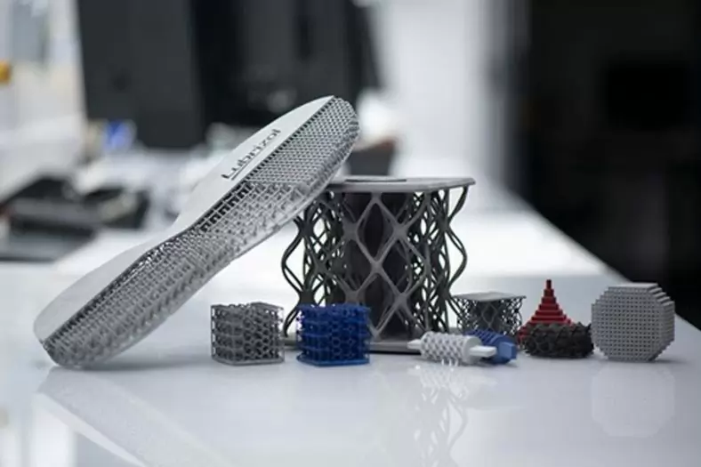
- Lattice Types: Experiment with different lattice types, such as honeycomb, gyroid, or octet, to find the most suitable pattern for your component’s load requirements.
- Infill Density: Adjust the density of the lattice infill pattern to strike a balance between strength, weight, and material consumption.
- Uniform Stress Distribution: Lattice structures distribute stress more uniformly, reducing the risk of localized failures and increasing overall structural resilience.
Stress Analysis and Simulation for Identifying Weak Points
Conducting stress analysis and simulation using software tools allows designers to predict how components will behave under specific loads and conditions. This approach helps identify potential weak points or areas of concern before physical production.
- Virtual Prototyping: Simulate real-world scenarios and loads on the assembly to identify areas where components might fail or deform.
- Material Properties: Utilize accurate material properties in simulations to ensure realistic results.
- Iterative Improvement: Analyze simulation results to make informed design changes that address weak points and improve component performance.
By incorporating these optimization techniques into the design process, designers can produce 3D-printed components that are not only lighter and more efficient but also better suited to withstand the stresses and forces they’ll encounter during operation. As we move forward, we’ll delve into designing for support structures, an important aspect of 3D printing that ensures successful fabrication of intricate components without compromising their structural integrity or surface finish.
Designing for Support Structures
Support structures are an essential aspect of 3D printing, especially for complex geometries and overhangs. They provide temporary support to prevent sagging, warping, and other issues during the printing process. In this section, we’ll explore the significance of support structures, strategies for incorporating self-supporting angles and overhang considerations, and techniques to minimize support material and post-processing efforts.
Understanding the Importance of Support Structures in 3D Printing
Support structures play a crucial role in maintaining the integrity of 3D-printed objects, particularly those with overhangs, bridges, and complex geometries. Without adequate support, these features may deform or fail during printing due to the lack of a solid foundation.
- Overhangs and Bridges: Components with overhangs—areas that extend beyond 45 degrees from the horizontal—require support to prevent material drooping and ensure accurate geometry.
- Layer Adhesion: Support structures also help ensure proper layer adhesion, reducing the likelihood of delamination or separation between layers.
- Surface Finish: Well-designed support structures can minimize post-processing efforts by providing a stable surface for the upper layers of the object to print on.
Incorporating Self-Supporting Angles and Overhang Considerations
While support structures are often necessary, designing components with self-supporting angles can minimize the need for extensive support material. This not only reduces printing time but also simplifies post-processing.
- Optimal Angles: Design components with angles that are self-supporting, typically ranging from 30 to 45 degrees from the horizontal. These angles allow the printer to bridge gaps without requiring supports.
- Avoiding Overhangs: Where possible, adjust the design to avoid extreme overhangs altogether. Reducing the number of overhangs can significantly reduce the need for supports.
Minimizing Support Material and Post-Processing Efforts
While support structures are essential, minimizing their use helps reduce material consumption and post-processing efforts, ultimately contributing to a more efficient and cost-effective printing process.
- Support Density: Adjust the support structure density in your slicing software to balance stability with material usage.
- Tree and Branch Structures: Some slicer software allows you to generate tree or branch-like support structures that minimize contact with the printed object, making removal easier.
- Easy-to-Remove: Design supports with easy-to-remove attachment points. This reduces the likelihood of damaging the printed component during support removal.
- Design for Accessibility: Ensure that support material can be accessed and removed without damaging the main component or leaving unwanted remnants.
Designing for support structures is a crucial aspect of 3D printing that directly influences the quality and success of the final printed object. By understanding the role of support structures, incorporating self-supporting angles, and minimizing the need for excessive support material, designers can streamline the printing process, reduce post-processing efforts, and create high-quality components with intricate geometries. With this knowledge, we’ll move on to exploring the realm of material selection, a pivotal step in achieving the desired properties and performance characteristics of 3D-printed assemblies.
Material Selection for Assembly Components
Choosing the right material for 3D-printed assembly components is a critical decision that impacts not only the functional performance of the assembly but also its durability, aesthetics, and overall cost. In this section, we’ll provide an overview of common 3D printing materials and their properties, discuss the process of matching material properties with assembly requirements, and explore strategies for balancing material cost and performance.
Overview of Common 3D Printing Materials and Their Properties
The range of materials available for 3D printing has expanded significantly, offering diverse options to meet various application requirements. Some common 3D printing materials include:
Plastics (Polymers):
- ABS (Acrylonitrile Butadiene Styrene): Known for its strength and impact resistance, suitable for functional parts.
- PLA (Polylactic Acid): Biodegradable, easy to print, and available in various colors. Ideal for prototypes and consumer goods.
- PETG (Polyethylene Terephthalate Glycol): Combines strength and ease of printing, suitable for mechanical parts and outdoor use.
Engineering Plastics:
- Nylon: Offers durability, flexibility, and chemical resistance, suitable for functional prototypes and parts.
- Polycarbonate: Known for its high impact resistance and heat resistance, suitable for engineering applications.
- PP (Polypropylene): Flexible, lightweight, and chemical-resistant, ideal for living hinges and functional prototypes.
High-Performance Polymers:
- PEEK (Polyether Ether Ketone): Withstands high temperatures, chemical exposure, and mechanical stress, used in aerospace and medical industries.
- Ultem (Polyetherimide): Resistant to heat and flame, used in aerospace, automotive, and medical applications.
Metals:
- Aluminum 3D Printing: Lightweight and corrosion-resistant, used for lightweight structural components.
- Titanium 3D Printing: High strength-to-weight ratio, suitable for aerospace and medical applications.
- Stainless Steel 3D Printing: Offers durability, corrosion resistance, and thermal properties.
Matching Material Properties with Assembly Requirements
Selecting the appropriate material involves aligning the material’s properties with the assembly’s functional and performance requirements.
- Mechanical Properties: Consider factors such as tensile strength, flexibility, impact resistance, and fatigue life. Choose materials that can withstand the anticipated loads and stresses.
- Temperature Resistance: If the assembly will experience extreme temperatures, choose materials with appropriate thermal stability and resistance.
- Chemical Compatibility: Evaluate the assembly’s exposure to chemicals, solvents, or environmental factors that may affect the material’s performance.
- Aesthetics: Depending on the application, consider the desired appearance, surface finish, and color of the components.
Balancing Material Cost and Performance
Material cost is an important consideration in assembly design. While advanced materials offer superior properties, they may come at a higher cost. Balancing cost and performance involves finding a material that meets the required specifications without exceeding the project’s budget.
- Application-Specific Selection: Use high-performance materials where necessary, and consider more cost-effective options for non-critical components.
- Material Testing: Prototype and test different materials to ensure they meet performance requirements before committing to large-scale production.
- Bulk Ordering: Depending on the project scale, consider ordering materials in bulk to take advantage of cost savings.
By carefully considering the properties, requirements, and cost factors of different 3D printing materials, designers can make informed decisions that result in assemblies with optimal performance, durability, and cost-effectiveness. With the material selection process complete, we’ll move on to the post-processing and finishing techniques that transform 3D-printed components into polished, functional, and aesthetically pleasing assemblies.
Testing and Iteration for Assembly Refinement
The journey of designing 3D-printed assemblies doesn’t end with the initial design. Continuous testing, analysis, and iteration are essential to refine the assembly’s functionality, fit, and performance. In this section, we’ll explore the importance of prototyping and testing, the process of analyzing feedback and making iterative design improvements, and how to incorporate user feedback for optimization.
Prototyping and Testing Assemblies for Functionality and Fit
Prototyping is a crucial step that involves creating a physical representation of the assembly to assess its real-world performance. Testing at this stage helps identify potential issues and allows for adjustments before moving to production.
- Functional Testing: Verify that the assembly components work as intended, interacting smoothly and achieving their intended purpose.
- Fit and Tolerance Testing: Assemble the rapid prototype components to ensure proper fit, alignment, and engagement of mating features.
- Stress and Load Testing: Apply simulated loads or forces to assess how well the assembly can handle real-world conditions.
Analyzing Feedback and Making Iterative Design Improvements
After testing, analyze the results and feedback to identify areas that need improvement. Iterative design involves making adjustments based on this analysis to enhance the assembly’s performance.
- Identify Weak Points: Analyze test results and identify any components or areas that showed signs of failure or poor performance.
- Redesigning: Modify the design to address identified weaknesses. This may involve adjusting dimensions, altering material distribution, or optimizing geometry.
- Simulating Improvements: Use simulation software to predict how design changes will affect performance before making physical modifications.
Incorporating User Feedback for Optimization
User feedback is invaluable for refining the assembly’s usability and addressing any unanticipated issues that arise during real-world use.
- User Testing: Allow users to interact with the assembly and gather their feedback on usability, comfort, and any challenges they encounter.
- Feedback Analysis: Carefully analyze user feedback to identify patterns, common issues, and potential areas for improvement.
- Iterative Optimization: Based on user feedback, iterate on the design to enhance user experience, ergonomics, and overall satisfaction.
The iterative process of prototyping, testing, analyzing feedback, and making design improvements is a fundamental aspect of creating successful 3D-printed assemblies. Through continuous refinement, designers can enhance the assembly’s functionality, durability, and user experience, ensuring that the final product meets or exceeds the intended goals. As we move forward, we’ll explore the documentation of assembly designs, including creating comprehensive assembly instructions and digital design files that facilitate successful manufacturing and collaboration.
Documenting Assembly Designs
Creating comprehensive documentation for 3D-printed assembly designs is crucial to ensure successful manufacturing, accurate assembly, and effective collaboration. In this section, we’ll delve into the process of generating assembly documentation, including 2D drawings, exploded views, assembly instructions, and the use of digital design files and collaboration platforms.
Creating Comprehensive Assembly Documentation for Manufacturing
Assembly documentation serves as a bridge between the digital design and the physical assembly. It provides crucial information for manufacturing, assembly, quality control, and maintenance.
- Bill of Materials (BOM): List all components required for the assembly, including their part numbers, descriptions, and quantities.
- Material Specifications: Provide details about the chosen 3D printing material, its properties, and any specific requirements for printing.
- Tolerance Information: Include tolerances and clearances to ensure accurate fit and alignment.
2D Drawings, Exploded Views, and Assembly Instructions
2D drawings and exploded views provide clear visual instructions for assembling the components, ensuring that the assembly process is intuitive and error-free.
- 2D Drawings: Create detailed 2D drawings of individual components, highlighting critical dimensions, features, and mating surfaces.
- Exploded Views: Illustrate how components fit together by creating exploded views that show each part in its relative position within the assembly.
- Assembly Instructions: Develop step-by-step assembly instructions that guide users through the process, including details about sequence, fasteners, and tools required.
Digital Design Files and Sharing Platforms for Collaboration
In today’s digital age, collaboration is often facilitated by sharing design files and documentation online.
- CAD Files: Store and share the original CAD files in formats compatible with popular design software. This allows collaborators to access and modify the design as needed.
- 3D Model Files: Export 3D models in formats like STL or OBJ that can be used for 3D printing or visualization.
- Cloud-Based Platforms: Use cloud-based platforms to share files, collaborate in real-time, and track revisions. Examples include Google Drive, Dropbox, and Autodesk A360.
- Version Control: Implement version control to track changes and ensure that everyone is working with the most up-to-date design.
Effective assembly documentation bridges the gap between design intent and physical realization, ensuring that 3D-printed assemblies are produced accurately, assembled correctly, and function as intended. By providing clear and detailed information through 2D drawings, exploded views, assembly instructions, and digital design files, designers facilitate successful collaboration, manufacturing, and maintenance throughout the assembly’s lifecycle.
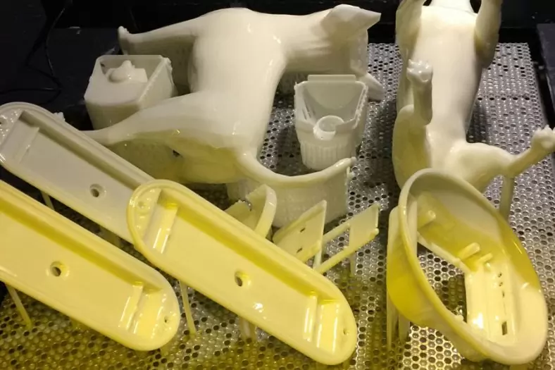
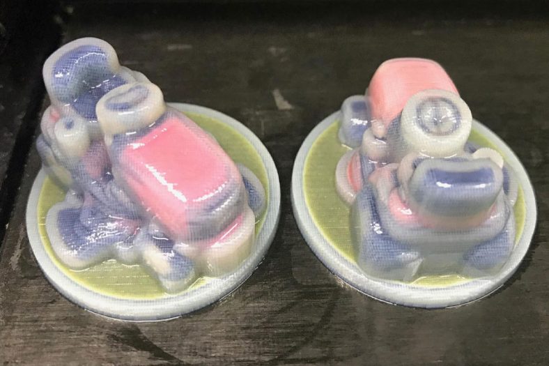
As we conclude this comprehensive guide, we’ll explore real-world case studies that showcase successful examples of 3D-printed assemblies, providing insights into challenges faced and innovative solutions devised by various industries.While it’s possible to design and print an assembly with articulating surfaces all in one print job, there are times when it’s better to stick with printing individual components for subsequent assembly. For example, if your separate components are made of different materials and colors and you don’t have a printer that can print using various materials, you will be forced to print them one at a time and assemble them afterward. Other projects have complex features, like intricate channels or large hard-to-reach gaps, which makes the support material difficult to remove. In a case like that, it’s also likely better to print separately and assemble afterward.
The Detail Of BE-CU 3D Printing Company
BE-CU.COM offers online 3D printing services for rapid prototyping and production in volume. Our clients are across a wide variety of industries and companies, including automotive, construction, aerospace, defense, electronics, machinery, industrial automation, medical, healthcare, consumer production, oil & gas, etc. Accelerate your product development and manufacturing process with our industry-leading metal & plastic 3D printing service and 3D printed parts. We’ll find the best 3D printing solution for your projects, to lower your cost and shorten the lead time based on your needs, while maintaining the quality. From 3D prototyping to end-use parts production, multiple materials are available for custom 3D printing parts. Need an alternative to the traditional solution? Submit your 3D CAD file to get an online quotation quickly. Our 3D printing service ensures accuracy and speed. We can help you choose the most appropriate technology and material to match your applications or request.
-
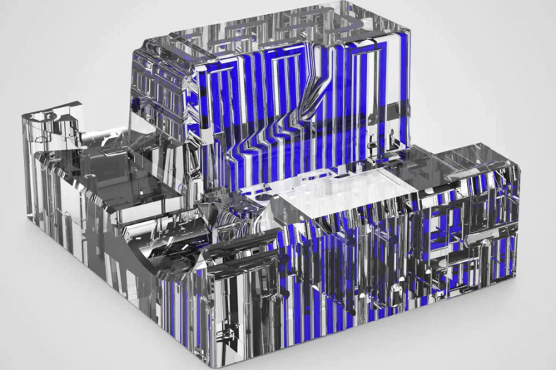
FDM 3D Printing Ultra-High Voltage Strong Electrical Connector
-
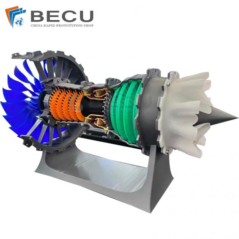
3D Printed Jet Engine Model
-

3D Printed Inconel Exhaust Manifold
-

3D Printed Black Myth: Wukong Model
-

Omni-Directional Surgical Planning Medical Models
-
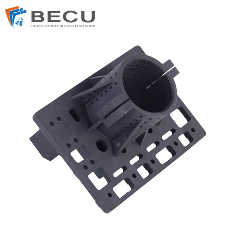
3D Printing Pool Pressure Cleaner Parts and Accessories
-
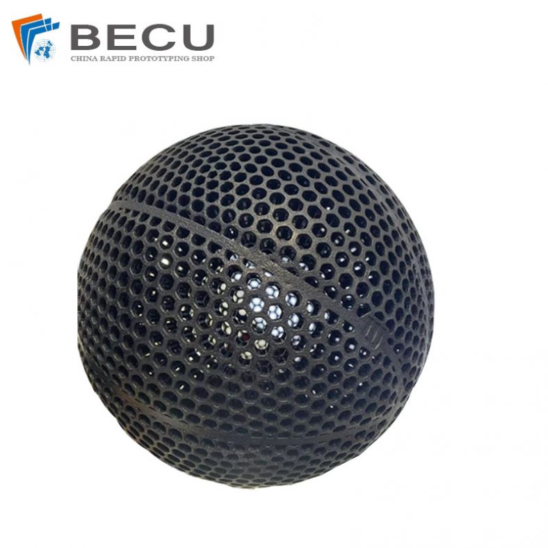
Nylon 3D Printed Size 5 Basketball
-
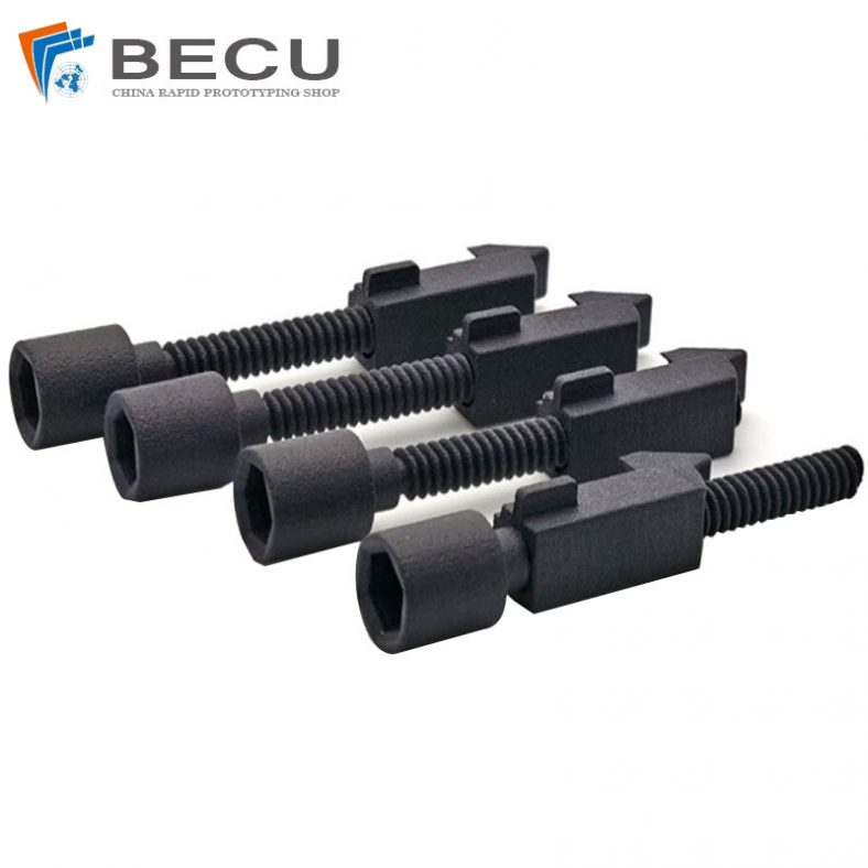
Black Nylon Medical Threaded Screw By MJF 3D Printing