In the process of metal spinning, the principal aim is to alter the shape of a blank, either diminishing or enlarging its diameter, while maintaining a consistent thickness, or allowing for minimal variation. This method is commonly referred to as Conventional Spinning or Non-thinning Spinning. As previously discussed, the fundamental techniques of Conventional Spinning encompass three primary methods: Deep Drawing Spinning, Diameter Reduction Spinning, and Diameter Expansion Spinning, in addition to various auxiliary forming techniques.
Deep Drawing Spinning(Extended Spinning)
As illustrated in the accompanying figure, a circular blank is firmly secured upon a core mold, with the spindle, core mold, and blank rotating together.
A pushing tool or spinning wheel is then employed to move along the core mold, effecting the desired shaping. When the intended form is achieved in a single operation, typically resulting in a coarse and short workpiece, this is termed Simple Deep Drawing Spinning.
Should the process lead to wrinkling or cracking, the tool may traverse along a designated path, as indicated by the dashed lines in the figure, performing several reciprocating motions until the final shape is achieved; this is known as Multi-pass Deep Drawing Spinning.
From the above, we discern that Deep Drawing Spinning utilizes a tool or spinning wheel alongside a core mold to draw the blank radially. The process involves radial stretching and circumferential contraction, marking it as the most prevalent and widely utilized technique within Conventional Spinning.
It is evident that Deep Drawing Spinning bears similarities to conventional stamping processes; however, it diverges significantly as it employs a tool or spinning wheel in conjunction with a core mold rather than a punch and die. This grants the operator a greater degree of freedom, allowing for the creation of more intricate hollow rotational shapes.
Manual Spinning
To illustrate the straightforward process of manual Deep Drawing Spinning, let us consider the examples presented in the figures. A flat blank—be it circular or polygonal—is concentrically compressed between the core mold and the tailstock, rotating in unison with the spindle.
A forming tool, resting on a pivot on the tool holder, is employed, utilizing leverage principles whereby the operator’s strength facilitates a significant force upon the blank.
This action moves the tool’s tip from the center to the outer edge and back again, imparting a series of arc-like oscillations that compel the blank to undergo plastic deformation toward the core mold. After each swing of the tool, it is incrementally advanced along the core mold’s axis, ensuring the blank gradually conforms until it completely adheres to the mold, ultimately shaping the desired workpiece.The push tool may operate in a single oscillatory motion or in a double reciprocating manner, with the latter evidently yielding superior results.
Figures depict instances of single-tool manual spinning. To enhance working conditions, a compound manual spinning approach is adopted, where two levers are employed. The left lever pivots at the tool holder, while the right lever is fitted with a spinning wheel at its end. The operator grasps both handles, coordinating the movements to manipulate the wheel, thereby shaping the blank as described. This design affords greater flexibility and efficiency than the single-tool method, enabling the operator to harness their physical strength more effectively. The introduction of rolling friction through the use of wheels reduces operational force, permitting the shaping of larger and thicker workpieces.
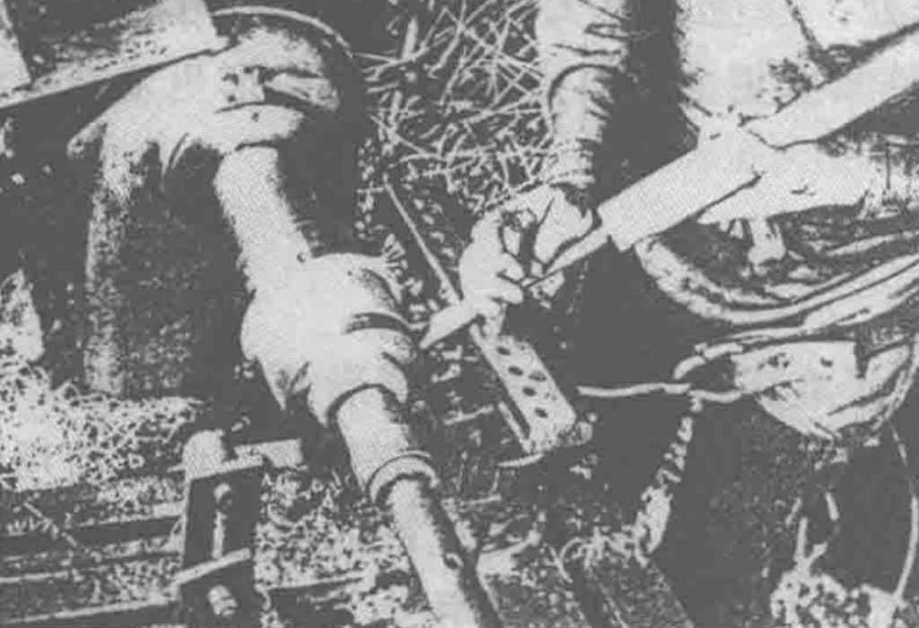
In earlier times, the tip of the push tool was fashioned from hardwood, later replaced by steel. To further minimize friction, wheels were introduced, followed by the development of a manual hydraulic servo-controlled spinning system. This system operates with guiding strips at either end, adjustable along a sliding track. The left push tool connects to the guiding strip, while the right push tool, equipped with a spinning wheel, engages through a pivot. Thus, a compound lever mechanism is formed.
As the operator manipulates the handles, the spinning tools follow suit in synchronized motion. The hydraulic system allows for substantial force application during the spinning process, enabling the formation of larger and thicker workpieces with ease and precision. This method, known as hydraulic-assisted manual spinning, boasts numerous advantages: it is agile and user-friendly, capable of producing robust and substantial items.
To better control the motion trajectory of the spinning wheel, a double-rod mechanical profiling device, as shown in Figure 2-7, has been designed. A spinning wheel (9) is mounted at the left end of the triangular main rod (7), while the right end connects to a sliding block motion pair (10 and 18) through a pivot (6). During operation, the pivot (6) only moves in a straight line. Another L-shaped compound rod (11) is connected at its apex to another pivot (8) on the main rod (7). A roller (13) is mounted on the short arm of the L-shaped compound rod, which makes contact with the profiling plates (12 and 15). The plate (15) can rotate around pivot (14); thus, (12) is the inlet section, and (15) is the profiling section, forming multiple positions such as (15, solid line), (15′), and (15”, dashed line), creating a series of excess profiling work curves—the trajectory line of the spinning wheel. During spinning, the sliding blocks (10 and 16) and spinning wheel (9) are first moved to an appropriate initial position in front of the blank. Then, the operator manipulates the compound rod (11) to make the profiling roller (13) contact the profiling plate and roll along the working edges of the profiling plate. This forces the main rod (7) and sliding block (10) to slide along the guide rail (18) while also rotating around pivot (6). In this way, the motion trajectory of the spinning wheel (9) aligns with each position of the profiling plate (e.g., (15), (15′), (15”)…). After the first pass, the flat blank is formed into shape I. For subsequent passes, the sliding block (16) needs to be moved incrementally to the left (i.e., the longitudinal feed amount), while rotating the profiling plate curve segment (15) to positions (15′), (15”), etc. The above process is repeated, gradually deepening the blank into shape II, III, etc., until the desired part is achieved.
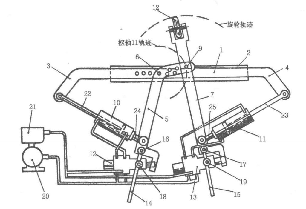
- 1-guide bar
- 2-slideway
- 3, 4-guide bar elbow
- 5, 7-left and right push rods
- 8-rotating wheel
- 6, 9-pivot
- 10, 11-oil cylinder
- 12, 13-follow-up valve
- 14, 15-handle rod
- 16, 17-fulcrum
- 18, 19-middle fulcrum
- 20-motor
- 21-oil pump
- 22, 23-piston rod
- 24, 25-earring
However, to make the operation more labor-efficient and to process larger and thicker parts, a semi-mechanical manual spinning method can be further facilitated with simpler mechanical devices. As shown in Figure 2-8, a metal-cutting lathe’s longitudinal and transverse sliding tool holder can be adapted by replacing the tool holder with a spinning wheel head. The operator uses both hands to control the handwheel and screw nut for longitudinal and transverse feed movements, achieving the coordinate motion trajectory of the spinning wheel and the goal of spinning. The magnifying effect of the screw pair’s helical transmission power not only reduces labor but also allows for spinning larger workpieces, achieving results that are difficult with ordinary manual spinning. However, this method requires skilled technique due to the need for coordinated operation with both hands. To further reduce effort and improve processing efficiency, hydraulic control valves and cylinders can be employed to facilitate manual spinning.An example of this is shown in Figure 2-6. Figure 2-9 presents another example using a hydraulic manual mechanism. Its structural working principle is as follows: a sliding frame (4) movable along guide rail (5) is mounted on the spinning machine’s spinning wheel frame, connected to a lever (7) at pivot (6). The other two pivots (9 and 15) of lever (7) connect to a swing plate (10) and the piston rod (16) of cylinder (13). The spinning wheel (8) is mounted at one end of the lever (7), and the other pivot (14) of the swing plate (10) is connected to the sliding frame (4), which also includes a hydraulic valve (17) and a control rod (11).Additionally, there is a hydraulic system. The working principle of the device is as follows: when the blank (1) is clamped and tightened between the core mold (2) and tail block (3), the spinning wheel (8) on the lever (7) is in its initial position.
Next, the hydraulic pump and spindle are started, causing the blank and core mold to rotate. When the control rod (11) swings clockwise, the oil hole A of hydraulic valve (17) opens, allowing oil from oil chamber C of the cylinder to flow back to the hydraulic valve’s oil tank via pipeline (18) and valve hole A, while pressure oil enters oil chamber B, pulling lever (7) and spinning wheel (8) to swing counterclockwise, resulting in forward bending deformation of the blank. Conversely, when control rod (11) swings counterclockwise, the cross-section of valve hole A decreases, increasing oil flow resistance, thereby raising the pressure in oil chamber C of cylinder (13), while oil in chamber B flows back to the tank via a pipeline (with a check valve) and overflow valve. At this time, the piston rod pushes lever (7) and spinning wheel (8) to swing clockwise, further deforming the blank in the opposite direction. After each swing, the sliding frame (4) moves a certain distance to the left. By repeatedly performing this process, the blank can gradually be formed. The force exerted by the cylinder and spinning wheel is proportional to the force and displacement applied to control rod (11), allowing the operator to apply a small force on control rod (11) to generate a significant spinning force on the wheel. The system pressure can be displayed on a pressure gauge. This structural design could also be adapted to make the end of the control rod compatible with the curve profiling plate, improving it into hydraulic profiling.
Figure 2-10 illustrates a hand-operated hydraulic spinning device based on the aforementioned hydraulic manual throttle control principle, featuring a single control rod and dual-cylinder bidirectional motion control. In this design, two hydraulic throttle valves (6 and 10) are jointly controlled by one control rod (13). When control rod (13) swings in the direction of arrows a or b, the conical needle valves (8 or 12) of valve rods (7 or 11) gradually cover the throttle holes of the valves, thereby increasing the pressure in the longitudinal and transverse cylinders on the spinning wheel frame, enabling sliding frames (1 and 3) to move forward or to the left. Conversely, when the control rod swings in the opposite direction, sliding frames (1 and 3) move in the opposite direction. When control rod (13) swings towards the middle (diagonal) between arrows a and b, the coordinate motion of the two cylinders is synthesized, allowing the spinning wheel to move in the corresponding composite direction.

In fact, this represents a dual-coordinate manual control method. It is well known that the ordinary spinning process evolved from manual ceramic processing, initially used for the processing of soft metal utensils and containers made of silver, tin, copper, etc., often performed on extremely simple wooden devices relying on human strength, with processing based on the sensation of tool vibration and sound. This requires skilled craftsmanship and therefore is subject to various limitations, including significant restrictions on batch size, quality, and productivity, making it generally suitable only for single items, small batches, or one-time products. However, manual spinning has advantages such as short processing time, simple equipment, and low product costs.
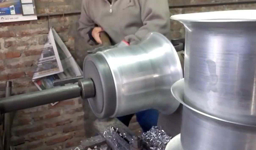
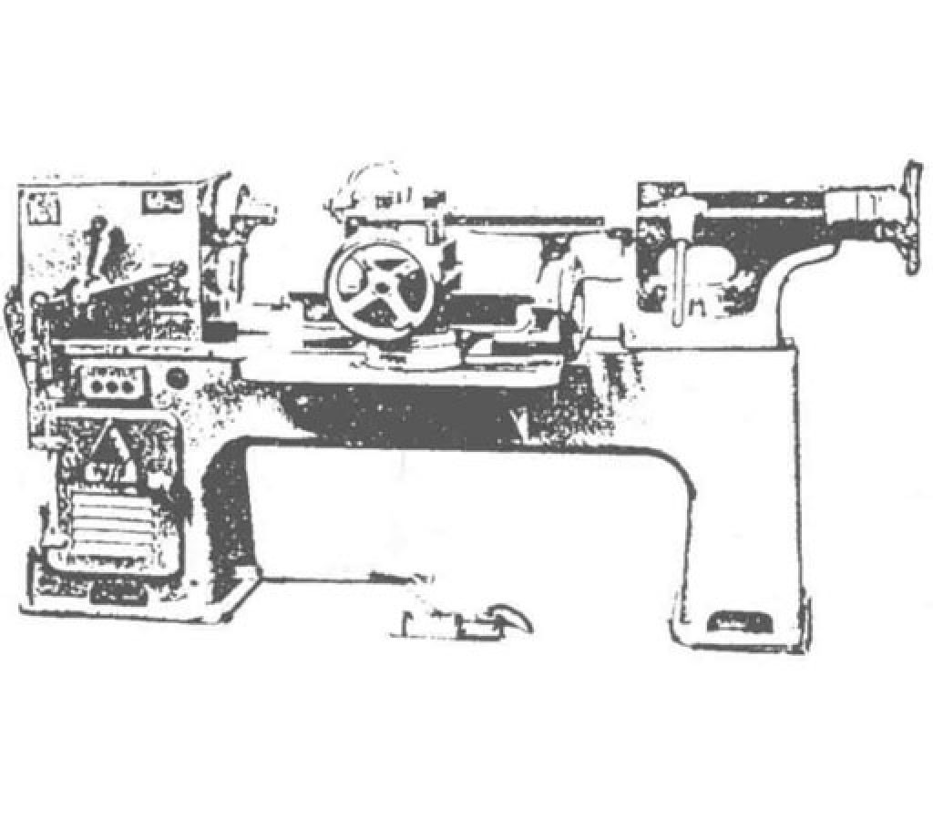
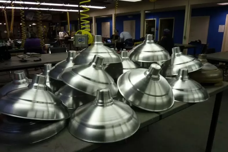
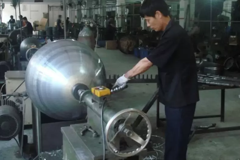
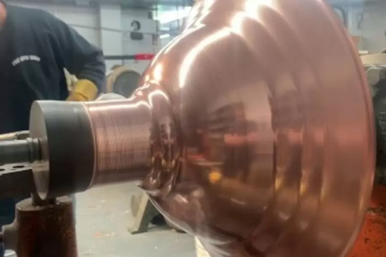
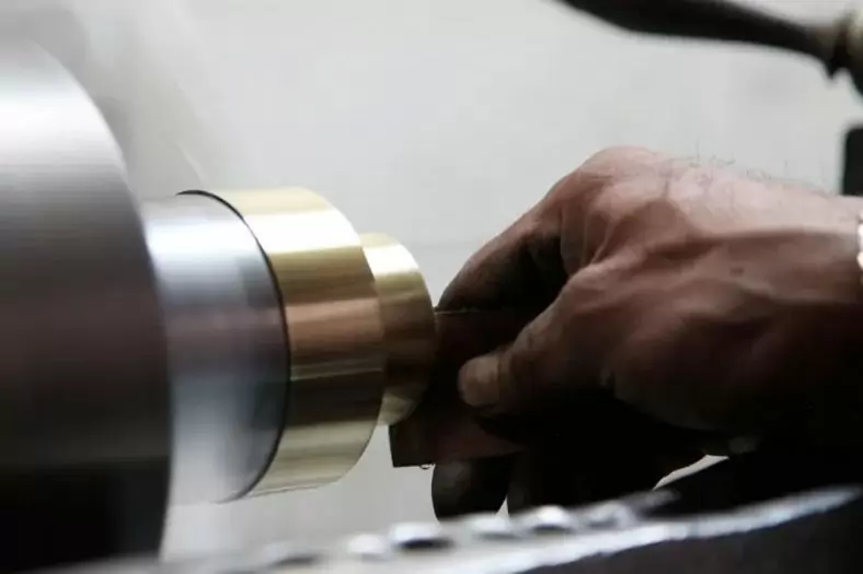
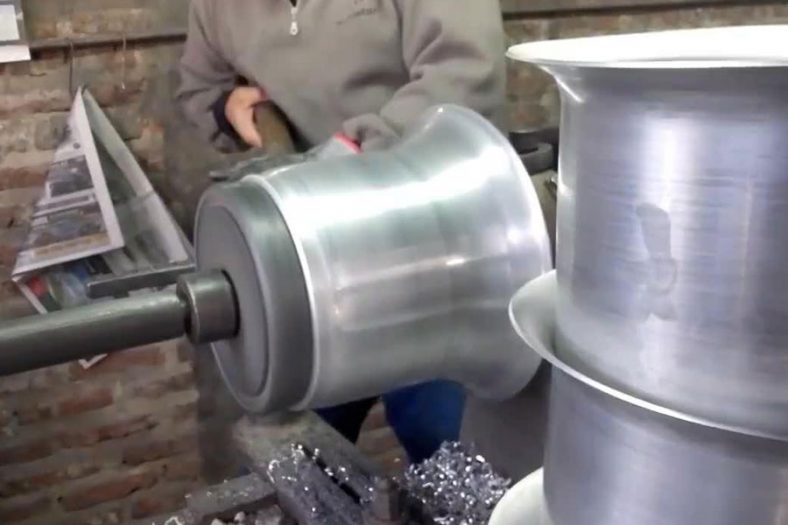
Figure 2-11 shows a more primitive manual spinning machine. Its spindle and core mold rotation are achieved by foot-operated pedals, transmitted through cranks, flywheels, ropes or belts, and pulleys. The blank is clamped manually on the core mold, and the spinning operation, as previously described, utilizes a lever. Later, with improvements and developments in this process and equipment, such as the adoption of hydraulic, steam, electric, and hydraulic drive for spindle transmission and spinning die, the intensity of physical labor has been significantly improved and reduced. Today, some factories, both domestically and abroad, still retain traces of some original operations. Externally, these devices resemble lathes. The three images shown in Figure 2-12 illustrate the evolution of manual spinning machines. In some factories, such as enamel factories, aluminum product factories, and lighting factories, one can see manual spinning machines modified from ordinary lathes.
Motorized (Automatic) Spinning
Motorized ordinary spinning has developed from manual spinning, where, except for loading and unloading materials, no direct human operation is required. This makes it suitable for processing larger workpieces and materials that are difficult to form using manual spinning. This not only expands the range of processing but also significantly improves production efficiency and product quality, providing possibilities for mass and automated production. The basic principles and processes of motorized spinning are not much different from those of manual spinning;
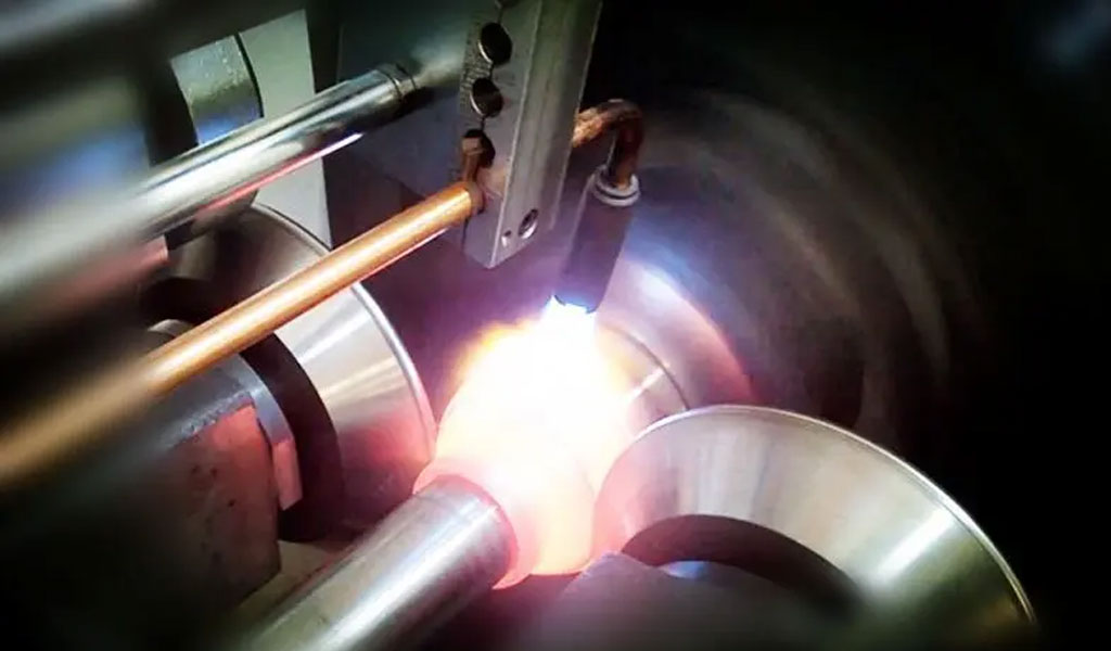
However, the equipment and tools used in motorized spinning are more refined, employing spinning wheels for deformation tools, and applying good lubrication and cooling during spinning for better processing results.To achieve the motorized spinning process, it is essential to control the motion laws of the spinning wheel (mainly referring to the motion trajectory during forming). The main methods include:
Mechanical Profiling Spinning
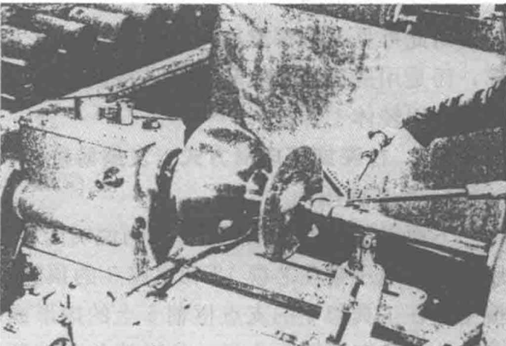
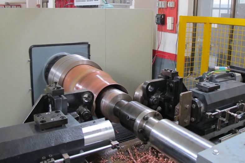
As shown in Figure 2-12, the lateral feed of the spinning wheel in the spinning machine utilizes a mechanical forced profiling tracking system. Before spinning, the spinning wheel frame and wheel are adjusted to an appropriate position relative to the blank. During spinning, the wheel exerts pressure on the blank, while a contact (roller or rolling bearing) is positioned behind the lateral sliding frame along with the profiling plate. During spinning, the two slide or roll closely against the working profile surface, allowing the lateral sliding frame and spinning wheel to follow a trajectory identical to the shape of the profiling plate’s working surface. After each spinning operation, the profiling plate position must be adjusted for the wheel to proceed to the next pass. Through several passes, the spinning can be completed. The working principle can be seen in Figures 2-6 and 5-101. Figure 2-13 shows a spinning machine modified from a conventional lathe, illustrating the use of mechanical profiling to spin a speaker horn. Due to the direct transfer of forming force to the contact surfaces between the touchpoint and profiling plate during spinning, the contact pressure between them is very high, leading to significant wear; therefore, this method is generally only used for forming small, thin-walled, and soft material workpieces.
Hydraulic Profiling Spinning
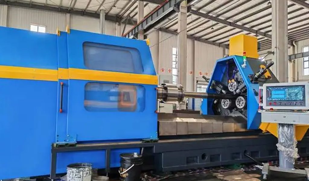
As the number of technicians engaged in manual spinning gradually decreases, and the demand for spinning grows rapidly, manual spinning has been replaced by modern automatic spinning. This new processing method does not require operators to have specialized skills or physical strength, yet it can process thick and large workpieces that are difficult to handle with manual spinning. Hydraulic profiling automatic spinning meets this requirement.
The hydraulic profiling system includes profiling devices, oil cylinders, and hydraulic and electric control systems. The hydraulic profiling device generally consists of a hydraulic profiling valve (or electro-hydraulic profiling instrument), a profiling head (touch point or roller), a profiling plate, a fixed support, and an adjustment mechanism. There are various structural forms for hydraulic profiling devices, but their working principles are fundamentally the same, as detailed in Chapter 4.8 and Chapter 5.6.5. During operation, the touch point (or roller) of the hydraulic profiling valve contacts the working profile surface of the profiling plate and can slide or roll. At this moment, any changes in the curve coordinates of the profiling plate’s surface will be reflected in the axial gap between the valve core of the profiling valve and the valve body, resulting in corresponding changes in the pressure and flow of the oil flowing through the valve and injected into the oil chamber of the cylinder. This allows the oil cylinder and spinning wheel to generate synchronized motion trajectories corresponding to the shape of the profiling plate’s working surface, and it enables automatic adjustment of the oil cylinder output and spinning wheel deformation force balance. Moreover, the spatial positioning of the profiling valve relative to the profiling plate and the spinning wheel relative to the core mold can be adjusted through the adjustment mechanism to achieve corresponding coordination, with automatic feedback adjustment between the profiling valve and lateral oil cylinder.
In addition to the hydraulic profiling, a so-called “electronic profiling” system has been developed. It consists of a displacement sensor and an electro-hydraulic servo valve as a combined unit. The sensor and the profiling touch point mounted on the magnetic core make up the profiling instrument, serving a similar role to the aforementioned profiling valve, also using a touch point or roller to contact the profiling plate, moving or rolling as required. The displacement changes detected by the sensor are output as electrical signals (voltage), amplified by a power amplifier, and sent to the servo valve’s motor, converting it into changes in oil pressure and flow that are fed to a mechanically linked oil cylinder (servo cylinder), producing similar synchronous motion to achieve profiling spinning.
This hydraulic profiling method represents a significant advancement compared to mechanical profiling, as the profiling force is small—typically less than 0.03 MPa (even smaller for electronic profiling)—while achieving a large spinning force (from thousands to tens of thousands of Newtons). It also boasts advantages such as operational balance, high efficiency, and long service life, with mature technology that can achieve equipment automation.
Numerical Control (NC and CNC) Spinning
1.CNC Spinning
In recent years, with the development and popularization of computers, CNC automatic spinning machines have rapidly advanced. These machines control equipment motion logic programs, processing data related to the movement trajectory of the spinning wheel, passes, and process parameters, allowing for quick and convenient control of the spinning machine. There are generally three control methods: NC (simple type), CNC (computer data type), and point-to-point teaching (PNC or A-D type); see Figure 4-299. There are various combinations of control methods and controlled components, and the data input methods for the spinning wheel passes and motion trajectories include 3 to 4 types.
The components of a CNC spinning machine system are shown in Figure 2-14. The core part of the system, the CPU, is generally a microcomputer (industrial control computer). It has a certain capacity and computational power, providing input, computation, and programming functions for processing data, as well as capabilities for judging, comparing, and correcting data from external sensor feedback inputs. There are two ways to issue instructions: one is to send commands to the controller via an information carrier (such as tape or disk) (offline control), and the other is for the CPU to send commands directly to the controller (online control). The system is divided into NC (simple numerical control) and CNC (computer numerical control) modes based on these two situations. In CNC systems, if a tape reader is included in the controller, offline control can often be performed as well.
With the advancement of numerical control technology, advanced computer CAD/CAM design methods have been adopted. This method eliminates the trouble of pre-programming and tape programming, significantly simplifying programming and saving time. The main advantages of CNC spinning include: eliminating the troublesome profiling devices for processing and adjustments, thus avoiding errors associated with these processes; shortening production preparation time and processing time; facilitating quick and convenient modifications of process parameters, aiding in the selection of optimal parameters; adaptability to various production situations and processing conditions, indicating strong adaptability; achieving high processing precision and good repeatability; and helping to prevent accidents.
Point-to-Point Teaching (PNC) Spinning
The point-to-point teaching system (also known as a self-learning system or information reproduction system) has developed from CNC spinning and was pioneered by the British. It is suitable for ordinary spinning processes and equipment. The A-D system shown in Figure 4-274 exemplifies this method. Figure 2-15 illustrates the equipment and operation. This system uses microcomputer processing technology, and the general steps for forming processing are as follows: First, an operator skilled in spinning operates a lever to move the wheel and test the workpiece. A series of movements from the lever is converted into electrical signals (analog) by sensors, which are then transformed into digital signals by an analog-to-digital (A-D) converter in the control panel and input into a microprocessor. The digitized spinning processing data is stored on a magnetic tape or disk for future use, generally after testing several workpieces and recording all information.
When officially spinning a workpiece, the wheel is set to the starting position, a tape or disk is loaded, the best processing information for the workpiece is retrieved, and pressing the start button will reproduce the spinning process for that workpiece. The processing speed can be adjusted to 3 to 4 times the input data to achieve high efficiency and quality.
Similar to the CNC control mentioned above, there are various teaching methods, including lever teaching, digitized drawing methods, and offline CAD/CAM drawing design methods.
The main features of the point-to-point teaching system spinning method are:
- Like the CNC system, it eliminates the need for a complex set of profiling plates and devices.
- It allows for process optimization to achieve high-quality products.
- Spinning speeds can be increased by 3 to 4 times compared to conventional spinning methods, resulting in high productivity.
- The system can implement pressure control and position control methods, maintaining a constant gap between the spinning wheel and core mold.
- Non-mechanical time during the spinning process can be automatically eliminated, and process parameters are easy to modify.
- The control system and operational programming are simpler than those of the CNC method, leading to lower costs.
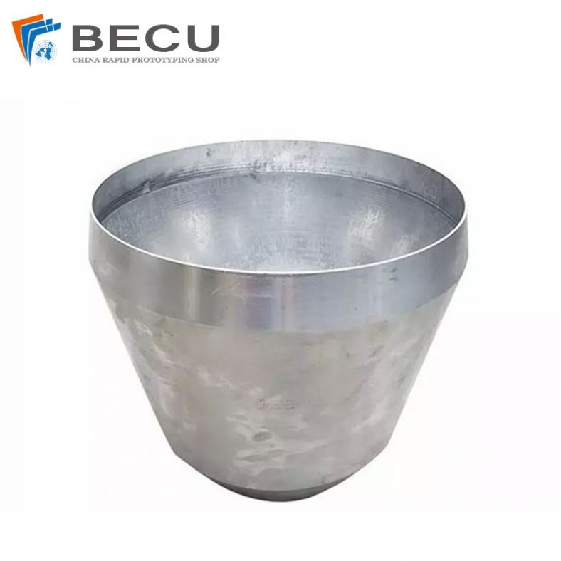
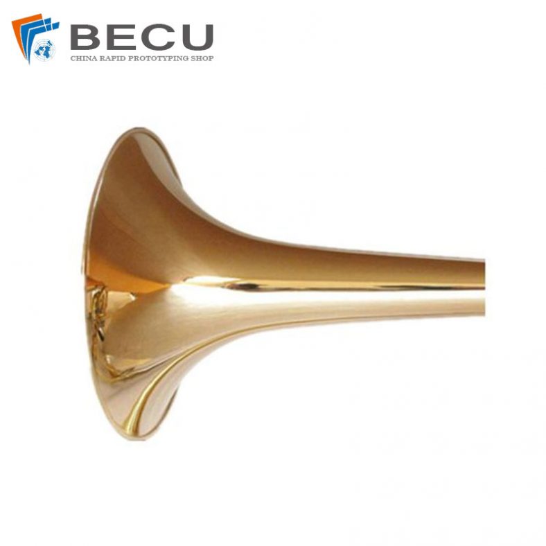
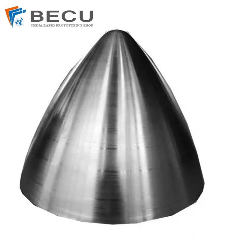
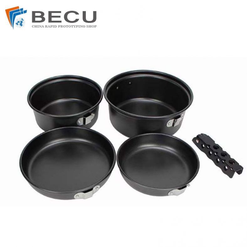
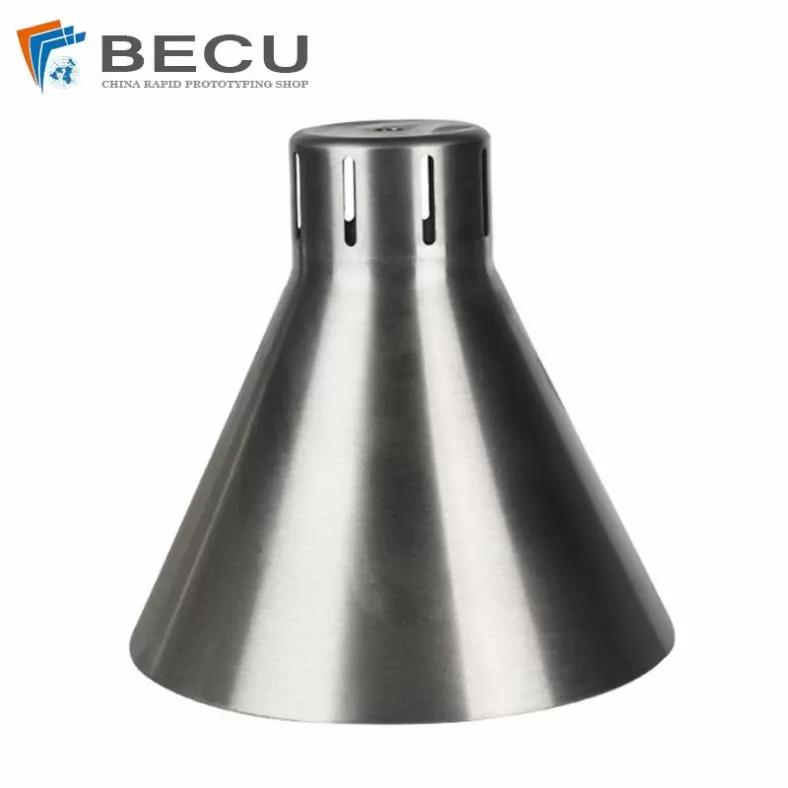
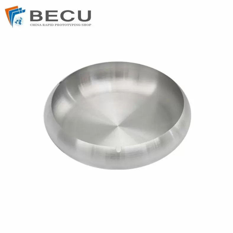
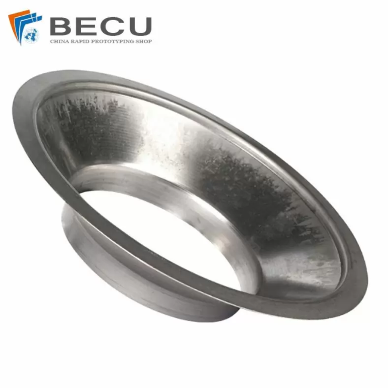
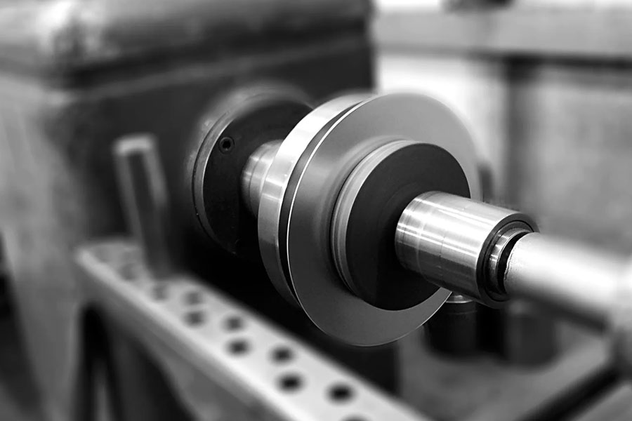
The Shapes Achieved Of Metal Spinning Parts
Simple shapes are easy to make in less time. But for complex shapes, it requires more time because it increases steps as per the block shape.
In addition to metal spinning, Be-cu.com also offers in-house tooling, welding, abrasive polishing and hydroforming, helping to drive down your costs and streamline production. Quicker turnaround times and lower costs are two of the most attractive advantages of metal spinning. The ability to form very thick components and large diameters with uniformity and high quality at low and high quantities, are more appealing reasons to consider metal spinning.To find out if metal spinning would be beneficial for your application or end product, contact us today.
- Domed
- Flanged
- Domed with flange
- Dished
- Semi elliptical
- Hemisphere
- Flanged, dished and flued
- Trumpet
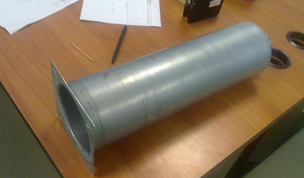
The Detail Of BE-CU Metal Spinning Company
At Be-cu.com, we use a variety of materials for metal spinning such as cold rolled steel, hot rolled steel, aluminum spinning, stainless steel spinning, brass, copper spinning and exotic metals such as titanium and inconel. Be-cu Metal Spinning Section specializes in the forming of stainless steel. With our automated metal spinning lathes and the capabilities of our deep drawing, stamping and welding equipment, our ability to form your part to your specifications and within your budget are realistic. Be-cu Metal Spun Company has over 30 years of metal forming experience and has used the large metal spinning technology for a variety of industries such as aerospace, automotive, military, ordnance, plastics, lighting, pharmaceuticals, dairy, etc…
We have engineers on staff with metal spinning expertise to help guide you on designing a custom part and choose the optimal process to produce high quality spun parts at a competitive and affordable price. Tooling is custom made to form parts to your configuration.