Spinning U-shaped annular grooves represent a specialized area of engineering and materials science, combining principles of mechanical design, tribology, fluid dynamics, and manufacturing technology. These grooves, characterized by their circular, U-shaped cross-sectional geometry, are formed through spinning processes and find applications in industries ranging from aerospace to heavy machinery. This article provides a comprehensive exploration of the design, mechanics, manufacturing, and applications of spinning U-shaped annular grooves, drawing on scientific literature and engineering principles to present a detailed and authoritative account. The discussion includes comparative analyses, detailed tables, and insights into recent advancements, aiming to serve as a definitive resource for researchers, engineers, and practitioners.
1. What Is U-Shaped Annular Grooves
Annular grooves are concentric, ring-like features machined or formed into a surface, typically cylindrical or planar, to serve functional purposes such as reducing friction, enhancing lubrication, or managing wear in mechanical systems. The U-shaped variant, distinguished by its rounded bottom and straight or slightly curved sidewalls, is particularly valued for its ability to balance structural integrity with functional performance. Unlike V-shaped or rectangular grooves, the U-shape minimizes stress concentrations at the groove base, making it suitable for applications under high mechanical or thermal loads.
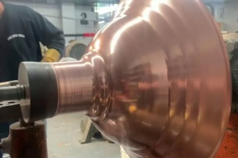
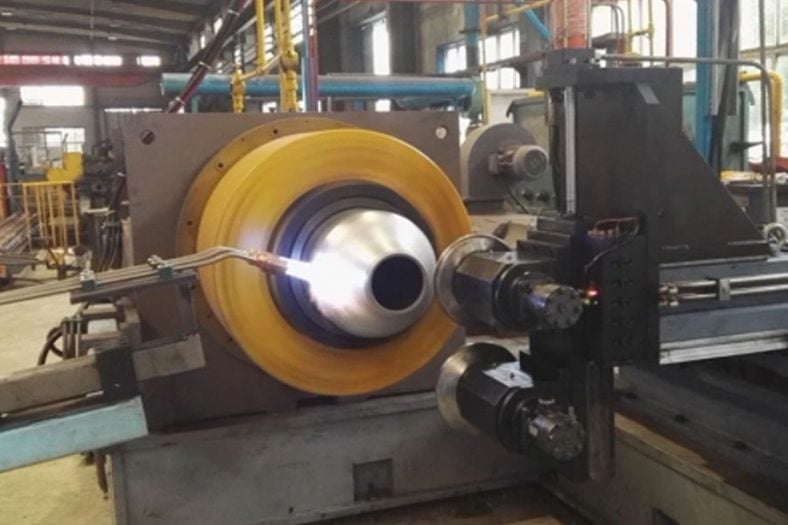
The process of spinning refers to a metal-forming technique where a rotating workpiece is shaped by applying localized pressure, often using a roller or tool, to deform the material plastically. Spinning U-shaped annular grooves involves creating these features on a rotating component, such as a sheave, bearing, or valve plate, to achieve precise geometries that enhance the component’s performance. This technique is widely used in industries requiring high-precision components, including automotive, aerospace, and heavy machinery.
The significance of U-shaped annular grooves lies in their ability to influence tribological properties, fluid flow, and mechanical behavior. For example, in bearings, these grooves can reduce abrasive wear by channeling debris away from contact surfaces. In hydraulic valves, they facilitate controlled fluid flow, enhancing efficiency. The spinning process, by enabling precise control over groove geometry, ensures consistency and repeatability, critical for high-performance applications.
This article delves into the historical context, design principles, manufacturing techniques, mechanical and tribological behavior, and practical applications of spinning U-shaped annular grooves. It also includes comparative tables to highlight differences in groove performance across materials, geometries, and applications, providing a robust framework for understanding this complex topic.
2. Historical Context and Evolution
The development of annular grooves and their integration into mechanical systems traces back to early industrial advancements in the 19th century, when engineers sought to improve the efficiency of rotating machinery. Early bearings and seals relied on simple grooves to retain lubricants, but these were often rectangular or V-shaped, limiting their durability under high loads. The introduction of U-shaped grooves emerged as a response to the need for features that could withstand cyclic stresses while maintaining effective lubrication.
The spinning process, as a method for forming metal components, gained prominence in the early 20th century with the advent of automated lathes and precision machining. By the 1940s, spinning was applied to create complex geometries in aerospace components, such as turbine blades and engine casings. The application of spinning to form U-shaped annular grooves specifically became notable in the context of hard disk drive bearings and hydraulic valves, where precise groove geometries were critical for performance.
Key milestones in the evolution of spinning U-shaped annular grooves include:
- 1940s: Introduction of helical and herringbone grooves in gas-lubricated journal bearings, laying the groundwork for modern groove designs.
- 1960s: Adoption of spinning techniques in the production of high-speed bearings for computer spindles, with U-shaped grooves improving lubricant retention.
- 1980s: Advances in computational fluid dynamics (CFD) enabled precise modeling of fluid flow through U-shaped grooves, optimizing their design for hydraulic systems.
- 2000s: Integration of laser processing and numerical simulations, such as finite element analysis (FEA), to refine groove geometries and enhance wear resistance.
- 2010s–Present: Application of U-shaped annular grooves in advanced materials, such as titanium alloys and composites, for aerospace and biomedical applications.
These developments reflect a convergence of materials science, manufacturing technology, and computational modeling, positioning spinning U-shaped annular grooves as a critical feature in modern engineering.
3. Design Principles of U-Shaped Annular Grooves
3.1 Geometric Considerations
The design of U-shaped annular grooves requires careful consideration of geometric parameters, including groove depth, width, radius of curvature, and spacing. These parameters directly influence the groove’s functional performance, such as its ability to retain lubricant, channel debris, or manage fluid flow. The U-shape is defined by its rounded bottom, which reduces stress concentrations compared to sharp-edged V-shaped or rectangular grooves, and its sidewalls, which may be vertical or slightly inclined to facilitate manufacturing or fluid dynamics.
Typical geometric parameters include:
- Depth (D): The vertical distance from the surface to the deepest point of the groove, typically ranging from 0.5 mm to 10 mm, depending on the application.
- Width (W): The horizontal distance across the groove, often 1–5 mm, influencing the volume of lubricant or fluid the groove can hold.
- Radius of Curvature (R): The radius of the rounded bottom, typically 0.1–1 mm, which minimizes stress concentrations.
- Spacing (S): The distance between adjacent grooves, affecting the density of grooves and their interaction with the contact surface.
- Wall Angle (θ): The angle of the sidewalls relative to the vertical, usually 0°–15°, impacting manufacturability and fluid flow.
These parameters are optimized based on the intended application, material properties, and operating conditions, such as rotational speed, load, and environmental factors.
3.2 Material Selection
The choice of material for components with U-shaped annular grooves is critical, as it affects both the spinning process and the groove’s performance. Common materials include:
- Steel Alloys: Q235 steel, stainless steel (e.g., AISI 304), and high-carbon chromium steel (e.g., AISI E52100) are widely used for their strength, ductility, and wear resistance. Steel is ideal for bearings and sheaves due to its ability to withstand high loads.
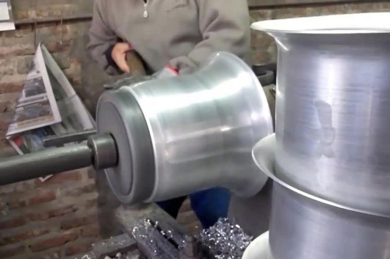
- Aluminum Alloys: Lightweight and corrosion-resistant, aluminum (e.g., AL-1050) is used in aerospace components where weight reduction is critical.
- Titanium Alloys: Ti-6Al-4V is employed in high-performance applications, such as aerospace and biomedical devices, for its high strength-to-weight ratio and biocompatibility.
- Polymers and Composites: In some low-load applications, polymers or fiber-reinforced composites are used for their low friction and ease of forming.
Material selection influences the spinning process, as ductile materials like aluminum are easier to spin than brittle ones like ceramics. Additionally, surface treatments, such as coatings or laser texturing, can enhance the tribological properties of the groove surface.
3.3 Functional Objectives
The design of U-shaped annular grooves is driven by specific functional objectives, including:
- Lubrication Retention: Grooves act as reservoirs for lubricants, reducing friction and wear in sliding or rotating contacts.
- Debris Management: By channeling wear particles away from contact zones, grooves mitigate abrasive wear, extending component life.
- Fluid Flow Control: In hydraulic systems, grooves regulate fluid flow, minimizing pressure drops and enhancing efficiency.
- Stress Distribution: The U-shape distributes mechanical stresses more evenly than sharp-edged grooves, reducing the risk of fatigue failure.
- Vibration Damping: Grooves can alter the dynamic response of a component, reducing vibrations in high-speed applications.
These objectives guide the optimization of groove geometry and material selection, often requiring iterative design processes supported by simulations and experimental testing.
4. Mechanics of Spinning U-Shaped Annular Grooves
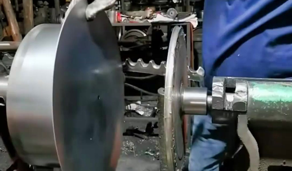
4.1 Spinning Process Mechanics
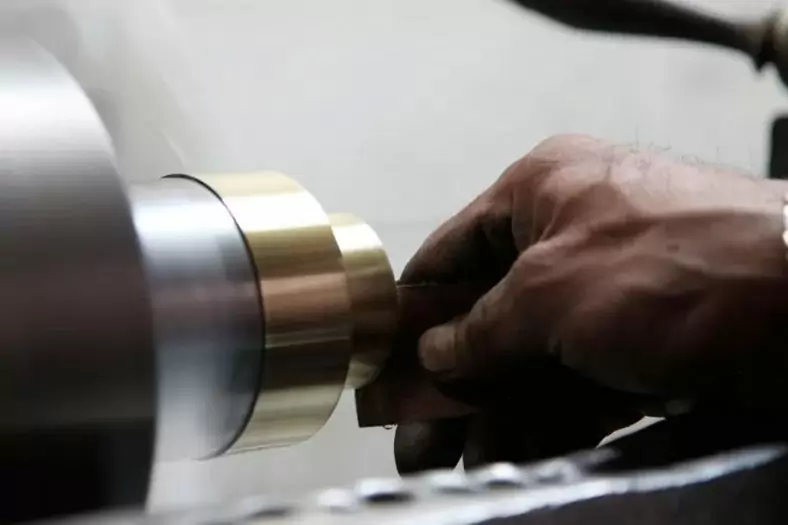
Spinning is an incremental forming process where a rotating workpiece is shaped by a roller or tool that applies localized pressure. For U-shaped annular grooves, the process involves:
- Workpiece Setup: A cylindrical or planar blank, typically made of metal, is mounted on a rotating mandrel or chuck.
- Tool Path Definition: A roller, often with a rounded tip to match the desired U-shape, follows a programmed path to deform the material incrementally.
- Plastic Deformation: The roller applies force to plastically deform the material, creating the groove while the workpiece rotates.
- Springback Compensation: After deformation, the material may exhibit springback, requiring adjustments to the tool path to achieve the desired geometry.
- Finishing: Post-spinning processes, such as polishing or laser texturing, refine the groove surface to meet tolerances.
The mechanics of spinning involve complex interactions between the tool, workpiece, and material properties. Key parameters include:
- Feed Rate: The speed at which the roller moves along the workpiece, typically 0.1–1 mm/rev, affecting surface quality and forming time.
- Roller Angle: The angle of the roller relative to the workpiece surface, influencing the groove’s sidewall geometry.
- Spindle Speed: The rotational speed of the workpiece, often 500–2000 rpm, impacting heat generation and material flow.
- Force Application: The force exerted by the roller, typically 1–10 kN, determining the extent of plastic deformation.
Finite element analysis (FEA) is commonly used to model the spinning process, accounting for material plasticity, friction, and springback. For example, ABAQUS simulations of Q235 steel sheave spinning have shown that groove depth is influenced by roller force and feed rate, with deeper grooves forming at higher forces but increased risk of material thinning.
4.2 Stress and Strain Distribution
During spinning, the workpiece experiences a combination of tensile, compressive, and shear stresses, leading to plastic deformation. The U-shaped geometry influences stress distribution:
- Tensile Stresses: Occur on the outer surface of the groove as the material is stretched.
- Compressive Stresses: Concentrate at the groove base, where the material is compressed by the roller.
- Shear Stresses: Develop along the sidewalls, facilitating material flow.
The rounded bottom of the U-shape reduces stress concentrations compared to V-shaped grooves, lowering the risk of crack initiation. However, improper tool paths or excessive forces can lead to defects such as wrinkling or tearing, as observed in sheet metal spinning of AL-1050 blanks.
Strain distribution is also critical, with higher strains occurring at the groove base and sidewalls. Experimental studies on Q235 steel sheaves have shown that the last-formed groove in a multi-groove spinning process is typically the deepest due to cumulative strain effects, with earlier grooves experiencing slight depth reduction due to subsequent spinning passes.
4.3 Tribological Behavior
The tribological performance of U-shaped annular grooves is a key factor in their effectiveness. Tribology, the study of friction, wear, and lubrication, is influenced by groove geometry, surface finish, and operating conditions. Key tribological phenomena include:
- Friction Reduction: Grooves supply lubricant to the contact zone, reducing the coefficient of friction. For example, tests on steel surfaces with U-shaped grooves under boundary lubrication showed a 30% reduction in friction force compared to smooth surfaces.
- Wear Mitigation: By channeling debris away from the contact zone, grooves reduce abrasive wear. Studies on journal bearings with helical U-shaped grooves reported a two-fold decrease in wear intensity in the presence of Al2O3 particles.
- Lubricant Retention: The U-shape’s rounded bottom and sidewalls create a reservoir for lubricant, ensuring continuous lubrication during operation.
- Debris Entrapment: In some cases, grooves collect wear particles, preventing them from causing further damage, as observed in railway axle bearings with annular grooves.
Tribological performance is optimized through surface treatments, such as polishing to achieve a roughness of Ra 0.02 μm, or laser texturing to create microdimples that enhance lubricant retention.
5. Manufacturing Techniques
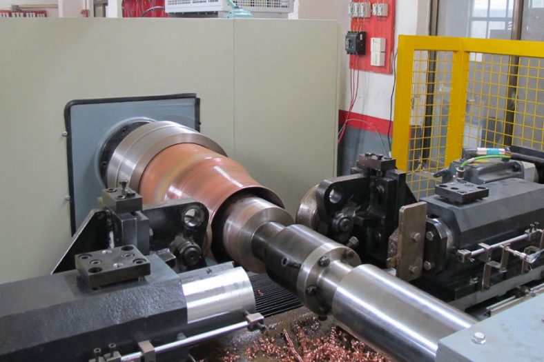
5.1 Conventional Spinning
Conventional spinning is the most common method for forming U-shaped annular grooves, particularly for large components like sheaves or bearing races. The process uses a CNC-controlled lathe or spinning machine, with a roller tool incrementally shaping the rotating workpiece. Key advantages include:
- Precision: CNC control ensures consistent groove geometry, with tolerances as low as ±0.01 mm.
- Versatility: Suitable for a wide range of materials, from aluminum to titanium alloys.
- Cost-Effectiveness: Low tooling costs compared to casting or forging for small to medium batch sizes.
Challenges include springback, which requires iterative tool path adjustments, and potential defects like wrinkling in thin-walled components. Recent advancements, such as haptic feedback systems, have improved operator control, reducing defects in complex geometries.
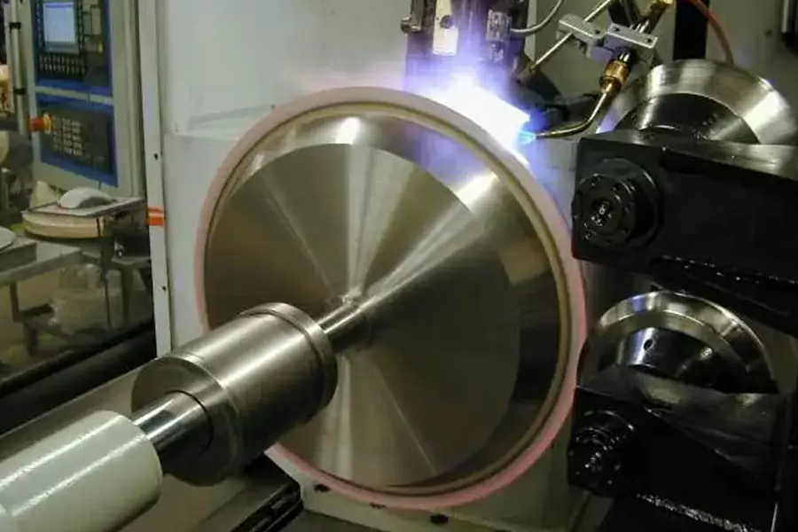
5.2 Laser-Assisted Spinning
Laser-assisted spinning combines traditional spinning with laser heating to enhance formability, particularly for high-strength materials like titanium alloys. The laser heats the workpiece locally, reducing yield strength and enabling deeper grooves without cracking. Benefits include:
- Improved Formability: Laser heating reduces the force required for deformation, enabling complex geometries.
- Enhanced Surface Quality: Localized heating minimizes surface defects, achieving roughness values as low as Ra 0.05 μm.
- Material Versatility: Suitable for brittle or high-strength materials that are difficult to spin conventionally.
However, laser-assisted spinning is more expensive due to the need for specialized equipment and precise control of laser parameters.
5.3 Laser Metal Deposition (LMD)
Laser metal deposition (LMD) is an additive manufacturing technique used to repair or create U-shaped grooves by depositing material into milled grooves. This method is particularly relevant for maintenance applications, such as repairing worn bearings or sheaves. Key features include:
- Repair Capability: LMD can restore damaged grooves to their original geometry, extending component life.
- Material Flexibility: Compatible with stainless steel, titanium alloys, and other high-performance materials.
- Precision: Laser control ensures accurate deposition, with groove depths up to 10 mm achievable.
Challenges include the need for inclined sidewalls to ensure proper bonding and the potential for thermal stresses during deposition.
5.4 Surface Finishing and Texturing
Post-spinning surface treatments enhance the performance of U-shaped annular grooves. Common techniques include:
- Polishing: Achieves low surface roughness (Ra 0.02–0.05 μm), reducing friction and wear.
- Laser Texturing: Creates microdimples or channels on the groove surface, improving lubricant retention and wear resistance.
- Coatings: Application of DLC (diamond-like carbon) or ceramic coatings reduces friction and enhances durability.
These treatments are tailored to the application, with polishing preferred for high-speed bearings and laser texturing for hydraulic valves.
6. Applications of Spinning U-Shaped Annular Grooves
6.1 Bearings and Seals
U-shaped annular grooves are widely used in journal and thrust bearings to reduce friction and wear. In hard disk drive bearings, chevron-patterned U-shaped grooves pump lubricant toward a central diameter, maximizing pressure and load-carrying capacity. Similarly, in mechanical seals, spiral U-shaped grooves generate hydrodynamic pressure, enabling non-contact operation and reducing leakage. For example, a study on spiral groove seals at 10,000 rpm showed an opening force of 1.2 kN with a leakage rate of 0.01 L/min.
6.2 Hydraulic Valves
In hydraulic systems, U-shaped annular grooves on valve plates control fluid flow, minimizing pressure drops and enhancing efficiency. The Hörbiger plate method, which uses annular grooves to create multiple metering edges, achieves high flow rates at small plate separations. CFD simulations of such systems have shown pressure drops as low as 0.3 bar at flow rates of 40 L/min, demonstrating the effectiveness of U-shaped grooves.
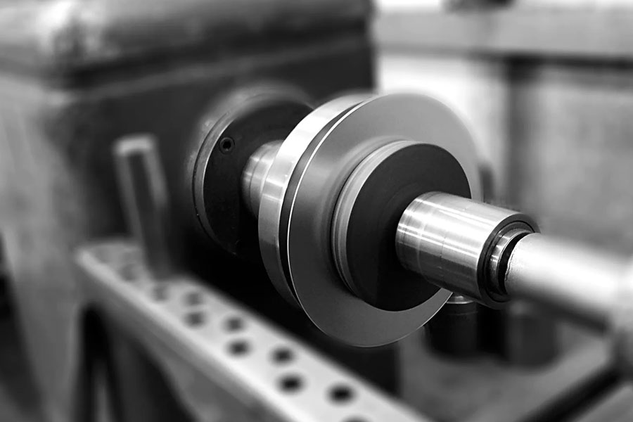
6.3 Sheaves and Pulleys
Large sheaves, such as those used in cranes or elevators, rely on U-shaped annular grooves to retain ropes or cables. Counter-roller spinning of Q235 steel sheaves ensures precise groove depths, with the bottom–middle–top spinning sequence minimizing defects. Experimental studies have shown that groove depth is linearly dependent on spinning parameters, with deeper grooves improving rope retention but increasing material stress.
6.4 Aerospace Components
In aerospace, U-shaped annular grooves are used in turbine blades, engine casings, and landing gear components to manage fluid flow and reduce weight. Titanium alloys like Ti-6Al-4V are often spun to create these grooves, with laser-assisted spinning enabling complex geometries. For example, grooves in turbine blades channel cooling air, reducing operating temperatures by up to 100°C.
6.5 Biomedical Devices
In biomedical applications, U-shaped annular grooves are incorporated into prosthetic joints and surgical tools to reduce friction and wear. Titanium or stainless steel components with polished or textured grooves ensure biocompatibility and longevity. For instance, hip implants with U-shaped grooves have shown a 20% reduction in wear rate compared to smooth surfaces.
7. Comparative Analysis and Performance Metrics
To provide a rigorous comparison of U-shaped annular grooves across applications, materials, and manufacturing methods, the following tables summarize key performance metrics based on scientific literature and experimental data.
| Parameter | Bearing Application | Hydraulic Valve | Sheave Application | Aerospace Component |
|---|---|---|---|---|
| Depth (mm) | 0.5–2.0 | 1.0–3.0 | 5.0–10.0 | 2.0–5.0 |
| Width (mm) | 1.0–3.0 | 1.0–2.0 | 3.0–5.0 | 2.0–4.0 |
| Radius of Curvature (mm) | 0.1–0.5 | 0.2–0.7 | 0.5–1.0 | 0.3–0.8 |
| Wall Angle (°) | 0–5 | 5–10 | 10–15 | 5–10 |
| Spacing (mm) | 2.0–5.0 | 1.0–3.0 | 10.0–20.0 | 5.0–10.0 |
| Primary Function | Lubrication Retention | Fluid Flow Control | Rope Retention | Fluid Channeling |
| Material | Yield Strength (MPa) | Ductility (% Elongation) | Wear Resistance | Spinning Feasibility | Typical Application |
|---|---|---|---|---|---|
| Q235 Steel | 235 | 26 | High | Excellent | Sheaves, Bearings |
| AISI 304 Stainless | 215 | 40 | Very High | Good | Valves, Biomedical |
| AL-1050 Aluminum | 105 | 12 | Moderate | Excellent | Aerospace Components |
| Ti-6Al-4V | 880 | 10 | High | Moderate (Laser-Assisted) | Aerospace, Biomedical |
| Polymer Composite | 50–100 | 5–15 | Low | Good | Low-Load Applications |
| Method | Precision (mm) | Cost (Relative) | Material Compatibility | Defect Risk | Typical Groove Depth (mm) |
|---|---|---|---|---|---|
| Conventional Spinning | ±0.01 | Low | Steel, Aluminum, Titanium | Moderate | 0.5–10.0 |
| Laser-Assisted Spinning | ±0.005 | High | High-Strength Alloys | Low | 2.0–15.0 |
| Laser Metal Deposition | ±0.02 | Very High | Steel, Titanium | Moderate | 5.0–10.0 |
| Polishing/Texturing | ±0.001 | Moderate | All | Low | Surface Only |
| Application | Friction Coefficient | Wear Rate (mm³/Nm) | Lubricant Retention (µL) | Debris Management |
|---|---|---|---|---|
| Bearings (Steel) | 0.05–0.10 | 1.0×10⁻⁶ | 50–100 | High |
| Hydraulic Valves | 0.08–0.12 | 2.0×10⁻⁶ | 20–50 | Moderate |
| Sheaves (Steel) | 0.10–0.15 | 5.0×10⁻⁶ | 100–200 | Low |
| Aerospace (Titanium) | 0.06–0.10 | 1.5×10⁻⁶ | 30–80 | High |
These tables highlight the versatility of U-shaped annular grooves, with performance tailored to specific applications through careful design and manufacturing choices.
8. Recent Advancements and Research Trends
8.1 Computational Modeling
Advances in computational modeling, particularly FEA and CFD, have revolutionized the design of U-shaped annular grooves. FEA models, such as those implemented in ABAQUS, simulate stress and strain distributions during spinning, enabling optimization of groove geometry to minimize defects. CFD simulations, using tools like ANSYS CFX, analyze fluid flow through grooves in hydraulic systems, ensuring minimal pressure drops and efficient performance. Recent studies have integrated machine learning with FEA to predict optimal groove parameters, reducing design iteration time by up to 50%.
8.2 Additive Manufacturing Integration
Additive manufacturing, particularly LMD, has expanded the possibilities for creating and repairing U-shaped annular grooves. Research on LMD of Ti-6Al-4V grooves has demonstrated the ability to achieve depths of 10 mm with minimal defects, offering a viable alternative to traditional spinning for complex components. Hybrid approaches, combining spinning with additive deposition, are also emerging, enabling the creation of multi-material grooves with tailored properties.
8.3 Surface Engineering
Surface engineering techniques, such as laser texturing and advanced coatings, have enhanced the tribological performance of U-shaped grooves. For example, laser-processed microdimples on groove surfaces have been shown to reduce friction by 20% in boundary lubrication conditions. Nanostructured coatings, such as graphene or DLC, further improve wear resistance, with applications in high-speed bearings and aerospace components.
8.4 Smart Materials and Sensors
The integration of smart materials, such as shape memory alloys, into components with U-shaped grooves is an emerging trend. These materials can adapt to changing loads or temperatures, enhancing groove performance in dynamic environments. Additionally, embedded sensors in grooves can monitor wear, pressure, or fluid flow in real time, enabling predictive maintenance in critical applications like aerospace and biomedical devices.
9. Conclusion
Spinning U-shaped annular grooves represent a cornerstone of modern engineering, combining precision manufacturing with advanced materials science to achieve superior performance in diverse applications. From reducing friction in bearings to controlling fluid flow in hydraulic valves, these grooves play a critical role in enhancing the efficiency and durability of mechanical systems. The spinning process, supported by computational modeling and surface engineering, enables the creation of tailored groove geometries that meet the demands of industries such as aerospace, automotive, and biomedical engineering.
Despite their advantages, spinning U-shaped annular grooves face several challenges:
- Manufacturing Precision: Achieving sub-micron tolerances in high-strength materials remains difficult, particularly for deep grooves.
- Material Limitations: Brittle or low-ductility materials, such as ceramics, are challenging to spin, limiting their use in some applications.
- Cost: Advanced techniques like laser-assisted spinning and LMD are expensive, restricting their adoption in cost-sensitive industries.
- Environmental Impact: The energy-intensive nature of spinning and surface treatments raises sustainability concerns, necessitating greener manufacturing methods.
Future research directions include:
- Sustainable Manufacturing: Developing low-energy spinning processes and recyclable materials to reduce environmental impact.
- Multi-Scale Modeling: Integrating micro- and macro-scale simulations to predict groove performance under complex loading conditions.
- Bio-Inspired Designs: Drawing inspiration from natural systems, such as the microgrooves in shark skin, to enhance groove efficiency.
- Automation and AI: Leveraging artificial intelligence to automate groove design and manufacturing, improving efficiency and reducing costs.
This article has provided a comprehensive overview of the design, mechanics, manufacturing, and applications of U-shaped annular grooves, supported by detailed comparative tables and insights into recent advancements. As research continues to push the boundaries of materials, modeling, and manufacturing, the future of spinning U-shaped annular grooves promises even greater innovation, with potential to address emerging challenges in sustainability, precision, and performance.
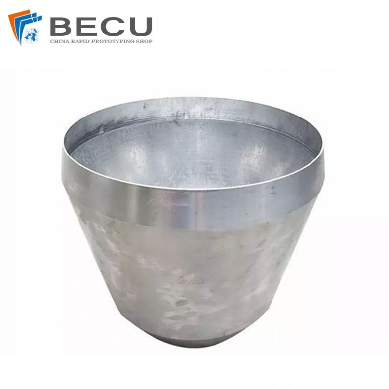
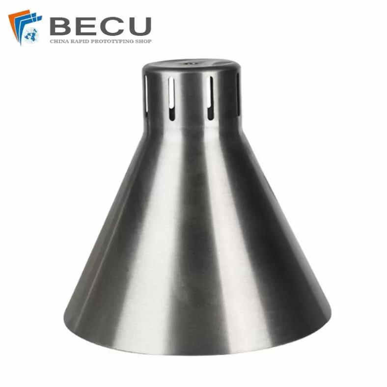
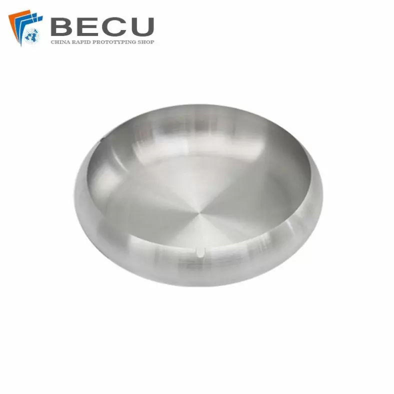
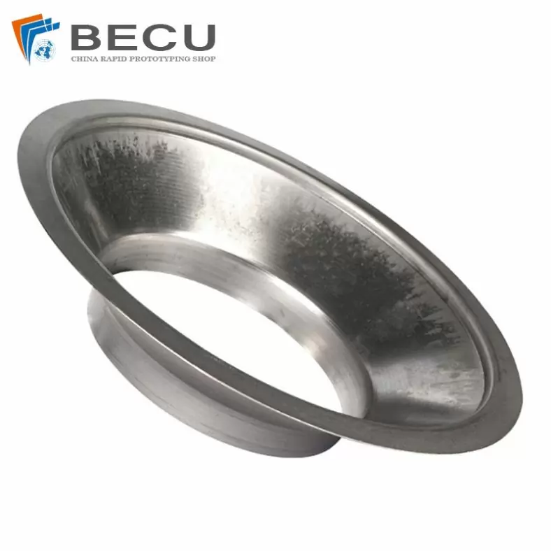
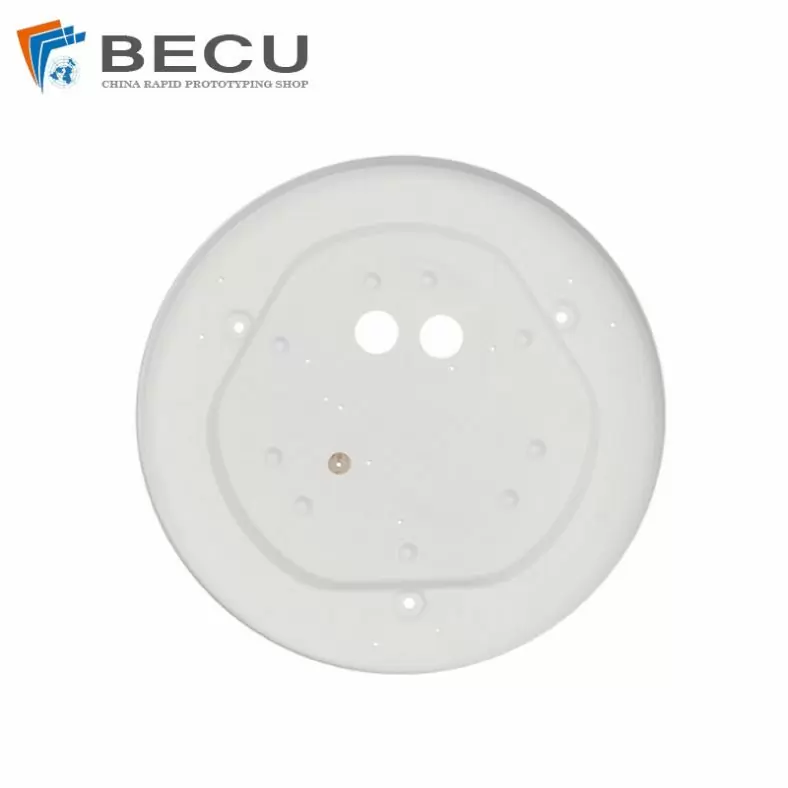
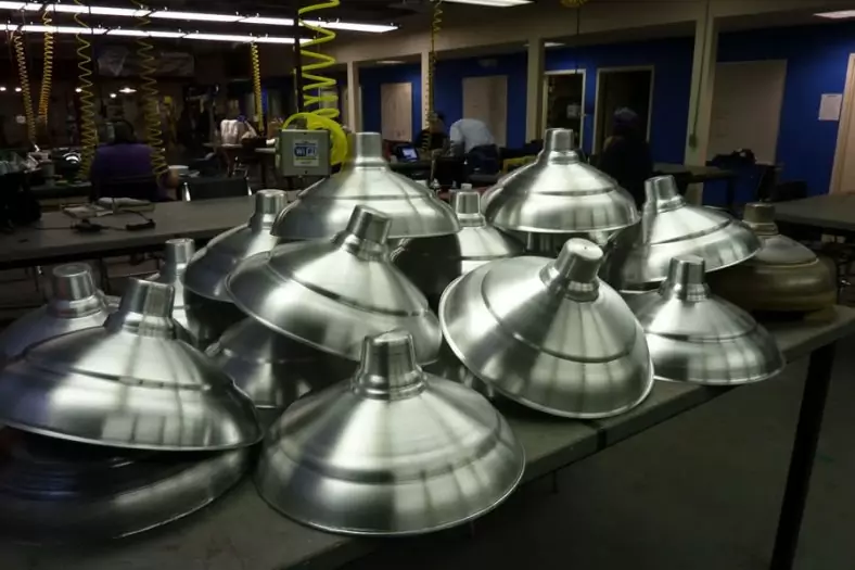
The Shapes Achieved Of Metal Spinning Parts
Simple shapes are easy to make in less time. But for complex shapes, it requires more time because it increases steps as per the block shape.
In addition to metal spinning, Be-cu.com also offers in-house tooling, welding, abrasive polishing and hydroforming, helping to drive down your costs and streamline production. Quicker turnaround times and lower costs are two of the most attractive advantages of metal spinning. The ability to form very thick components and large diameters with uniformity and high quality at low and high quantities, are more appealing reasons to consider metal spinning.To find out if metal spinning would be beneficial for your application or end product, contact us today.
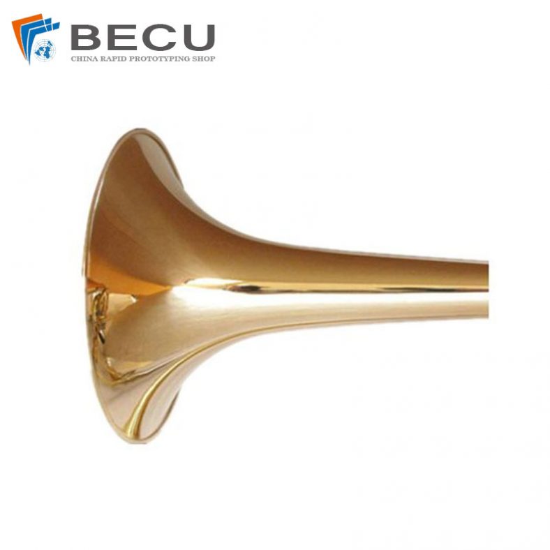
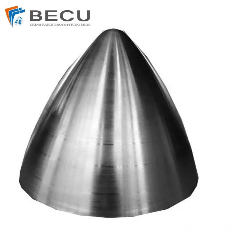
- Domed
- Flanged
- Domed with flange
- Dished
- Semi elliptical
- Hemisphere
- Flanged, dished and flued
- Trumpet
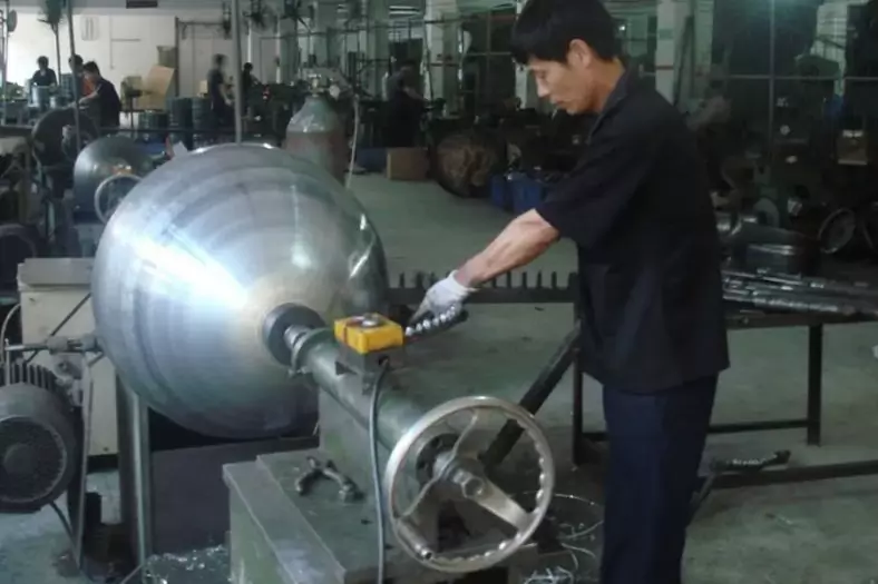
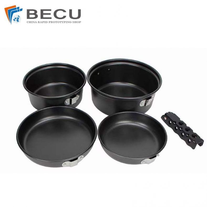
The Detail Of BE-CU Metal Spinning Company
At Be-cu.com, we use a variety of materials for metal spinning such as cold rolled steel, hot rolled steel, aluminum spinning, stainless steel spinning, brass, copper spinning and exotic metals such as titanium and inconel. Be-cu Metal Spinning Section specializes in the forming of stainless steel. With our automated metal spinning lathes and the capabilities of our deep drawing, stamping and welding equipment, our ability to form your part to your specifications and within your budget are realistic. Be-cu Metal Spun Company has over 30 years of metal forming experience and has used the large metal spinning technology for a variety of industries such as aerospace, automotive, military, ordnance, plastics, lighting, pharmaceuticals, dairy, etc…
We have engineers on staff with metal spinning expertise to help guide you on designing a custom part and choose the optimal process to produce high quality spun parts at a competitive and affordable price. Tooling is custom made to form parts to your configuration.