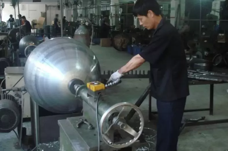
Expansion spinning is a metal forming process that utilizes radial forces to produce hollow parts with uniform wall thickness. This technique is distinguished by its ability to create intricate geometries and high-quality surface finishes, making it a popular choice in various industries, including aerospace, automotive, and medical.
The Define Of Expansion Spinning
Expansion spinning is a method where a spinning wheel is inserted into the interior of a rotating blank, applying radial forces outward to induce diameter expansion in the workpiece.
This technique is referred to as “expansion spinning,” or simply “exp spinning.”
Factors Influencing Expansion Spinning
The formability of expansion-spun components is primarily determined by the material properties, including tensile strength, yield strength, elongation, and reduction of area. Depending on the degree of diameter expansion required, it is often necessary to divide the deformation process into multiple passes. The guiding principle for determining the number of passes is to ensure that excessive stress and strain do not develop in the workpiece during the expansion process. Specifically, the stress must not exceed the material’s tensile strength to avoid rupture in the deformation zone. This risk exists for both seamless and welded blanks. For welded materials, cracking can occur not only at the weld joint but also within the base material.
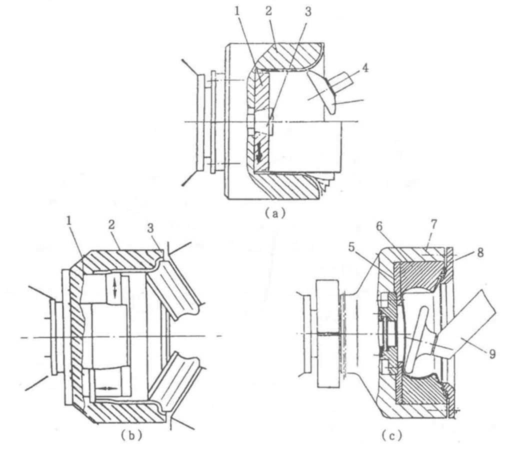
Furthermore, if the material exhibits a significant tendency for work hardening, fewer passes should be employed, with each pass maximizing the amount of expansion. Otherwise, due to severe hardening, intermediate annealing may be necessary; failure to perform this step could halt the process. As depicted in Figure 2-34a, multiple passes are used to expand the blank radially from the inside out. The ability of the workpiece to withstand expansion depends on the material’s elongation and the transverse feed rate of the spinning wheel for each pass. When designing the process, it is essential to consider the material’s elongation to identify the maximum allowable transverse feed rate.
For example, stainless steels, corrosion-resistant steels, and heat-resistant steels exhibit notable work hardening during cold spinning; however, their high elongation allows for larger transverse feed rates without the need for intermediate annealing. Assuming the wall thickness of the workpiece remains relatively unchanged during expansion, the maximum expansion ratio can be expressed in relation to the material’s elongation (ε) and calculated as follows:
ε={(Df-D0)/D0}*100%
Where D. ——diameter of blank before expansion;
Df is the diameter of the workpiece after expansion.
Consider a cylindrical blank with a diameter (D) of 500 mm and a wall thickness (t) of 1.5 mm, where the material has an elongation of 20%. If the target maximum diameter (Dₘ) after expansion is 560 mm, it becomes necessary to verify the feasibility of this process. The calculations yield that the actual elongation of 12% is less than the allowable elongation of 20%, confirming the viability of expansion spinning for this cylindrical workpiece.The verification is as follows:
Elongation ε={(Df-D0)/D0}100%={(560-500)/500}100%=12%
Additionally, it is natural for the wall thickness of the workpiece to decrease post-expansion, which can be approximated by the following condition: the ratio of the final wall thickness (tᵣ) to the original wall thickness (t) equals the inverse ratio of the workpiece diameters before and after expansion.
Tf/T0=D0/Df
So,Tf=(T0/D0)/Df=(1.6*560)/560=1.34mm
For thin-walled components, the inner diameter can be used for calculations, while for thick-walled blanks, the average diameter should be employed.
As previously noted, the formability during expansion spinning, along with the feed rate of the spinning wheel, is contingent upon the material properties.
Generally, materials with higher tensile strength are more conducive to expansion spinning than to reduction spinning, as the material is in a tensile state during expansion, reducing the likelihood of wrinkling compared to the compressive state encountered in reduction spinning. Thus, larger feed rates can be utilized for each pass.
Typically, the expansion process leads to some degree of thinning in the workpiece; however, with appropriate feed rates, the wall thickness can remain largely unchanged. Expansion-spun blanks are commonly fabricated from flat sheets, prefabricated forms, extrusions, stampings, and welded components.
In the preparation of welded blanks, strict control over the quality of weld seams and the metallurgical structure and properties of the heat-affected zone is crucial. The weld seams should be ground smooth before forming. To improve deformation conditions, normalizing post-welding is recommended. For carbon steel and structural steel cold-rolled sheets, submerged arc welding is advised; for stainless steel, tungsten inert gas (TIG) welding is preferred, and electron beam welding is suitable for high-stakes applications. Generally, for low-carbon steel welded cylindrical blanks, expansion ratios of 10% to 15% are achievable, with occasional successes reaching up to 28%; however, forming becomes significantly more challenging beyond 30%. Thus, the expansion ratio varies greatly depending on material properties and welding conditions.
The Process of Expansion Spinning
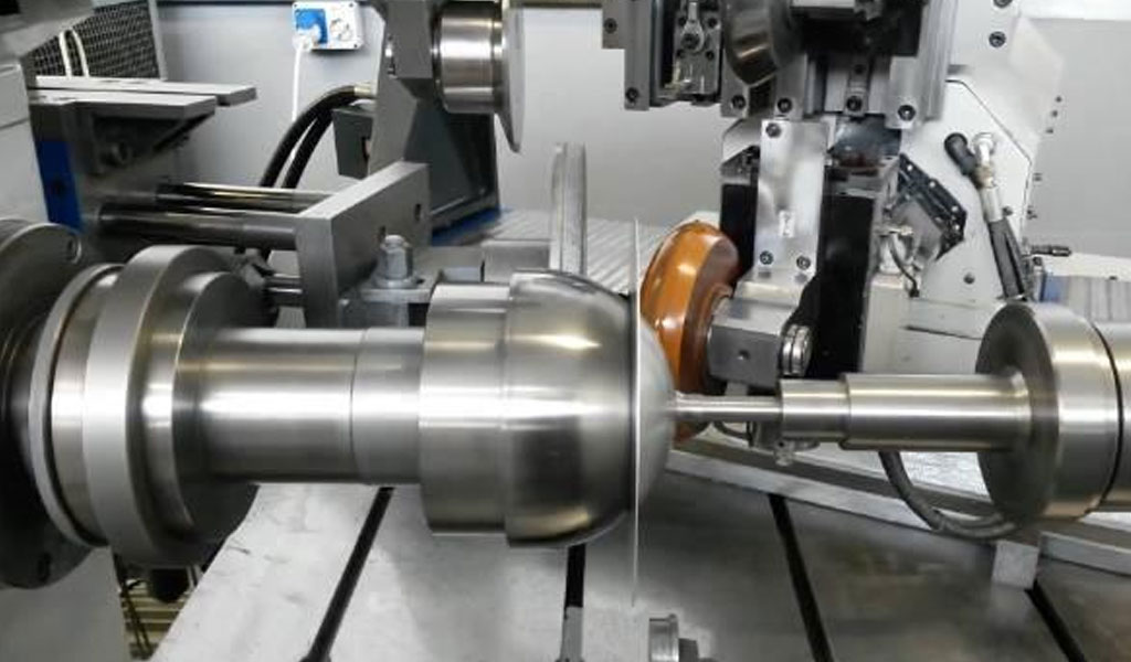
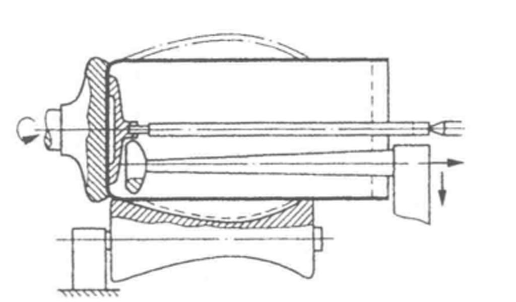
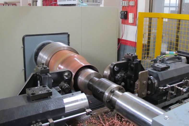
The expansion spinning process generally follows these steps: As illustrated in Figure 2-34, a prefabricated blank is placed into a hollow outer mandrel and secured with a mechanical or hydraulic clamping mechanism. When the spindle drives the mandrel and workpiece in unison, the spinning wheel penetrates the workpiece, performing several successive radial expansions from the inside out. This action facilitates the outward deformation of the blank until it conforms to the desired shape.
In scenarios involving thin-walled components or single items, manual spinning may be feasible, provided that skilled operational techniques are employed.
Common Methods of Expansion Spinning
Depending on the part being formed, several common methods of expansion spinning are employed:
Hollow Outer Mandrel Expansion Spinning
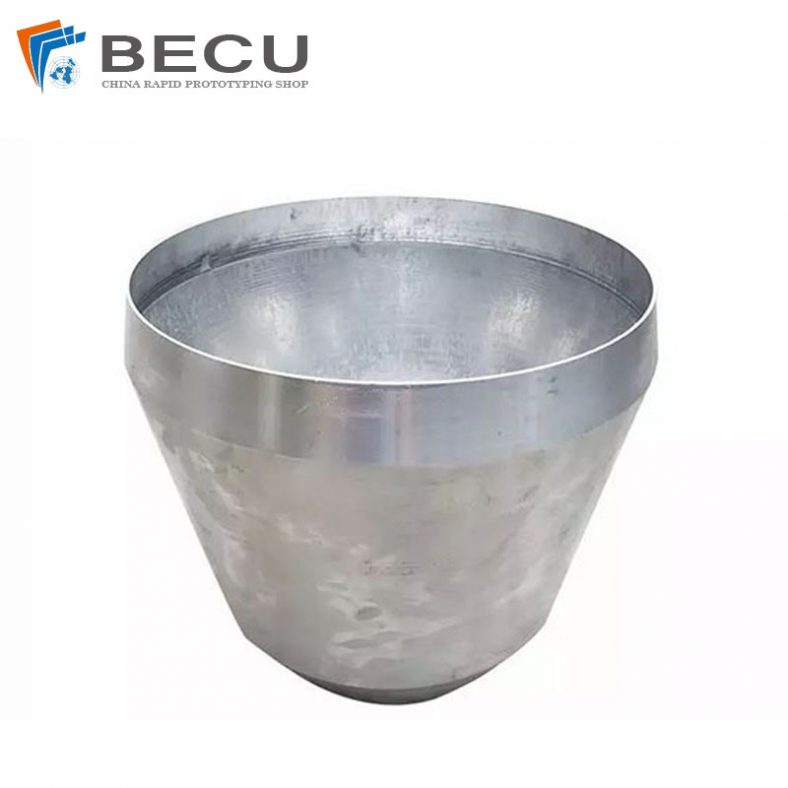
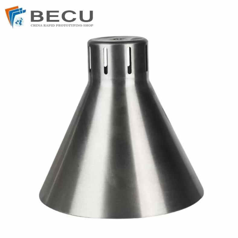
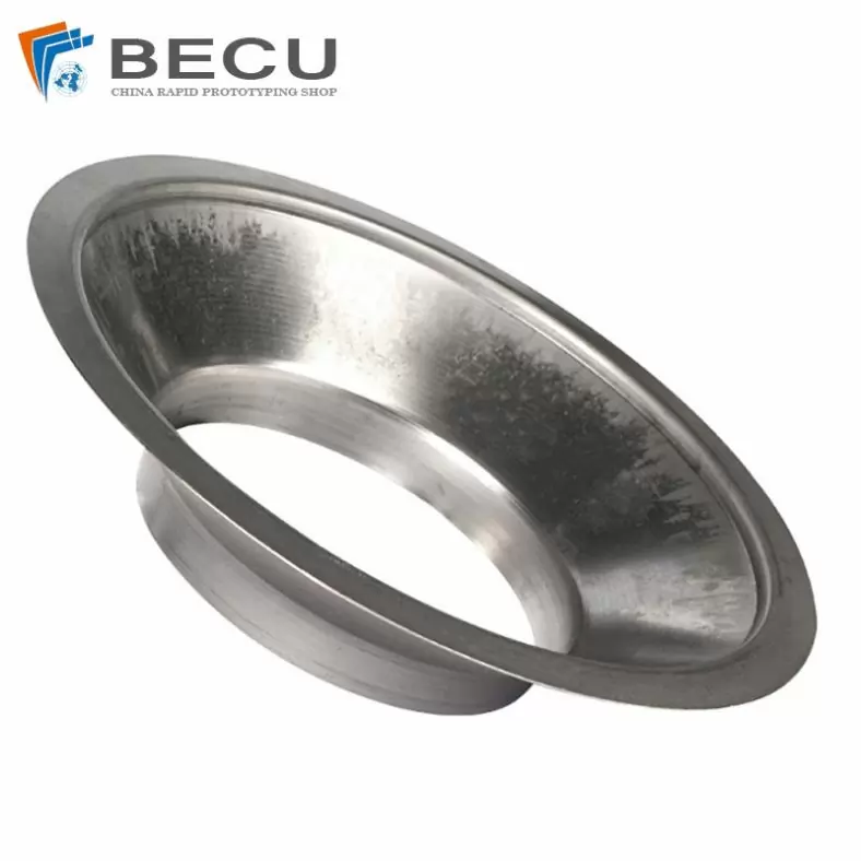
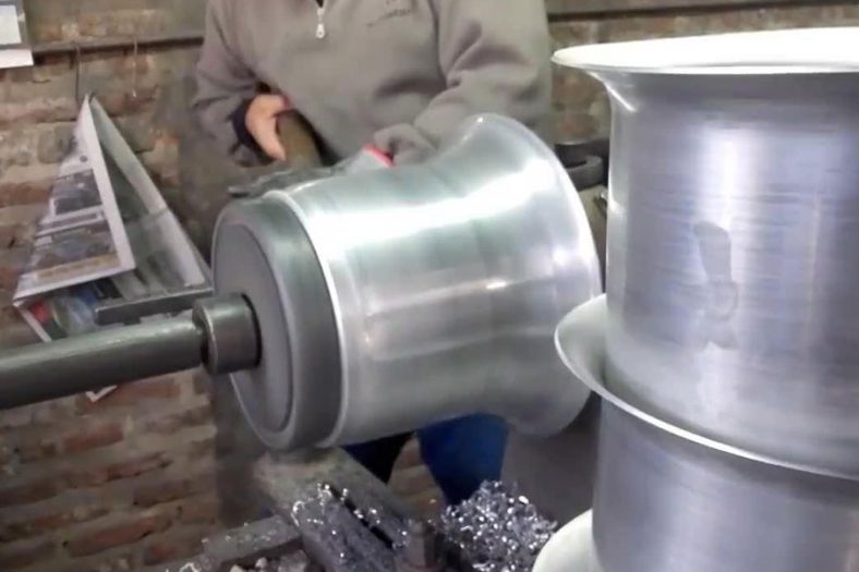
Illustrated in Figure 2-34, this method includes three examples: (a) the flared end of an expansion-spun workpiece, (b) the flanged end of a component (such as the outer edge of an automotive wheel), and (c) a mid-section “bulging” expansion.
External Rolling Wheel Expansion Spinning
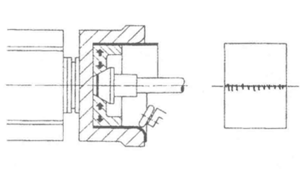
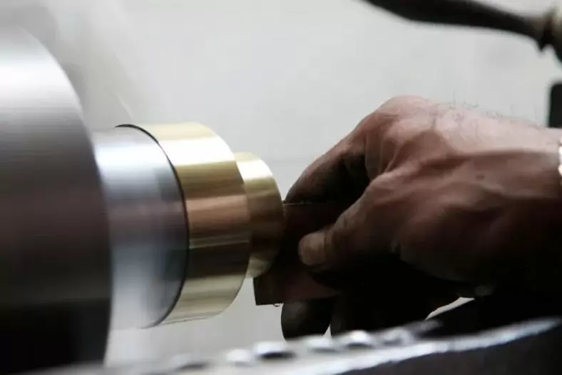
For moderate expansion requirements, the method depicted in Figure 2-36 employs an external rolling wheel as the mandrel. The prefabricated cylindrical blank is supported on a tray, secured by a tailstock center pin and pressure plate, which allows for rotation during spinning. The external rolling wheel, aligned with the workpiece’s shape, engages the internal surface of the blank to perform the spinning operation. This method offers advantages of simple structure, ease of machining, low cost, and versatility in processing various diameters with a single set of tooling.
Coreless Expansion Spinning
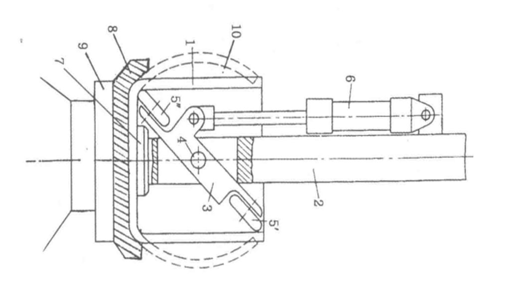
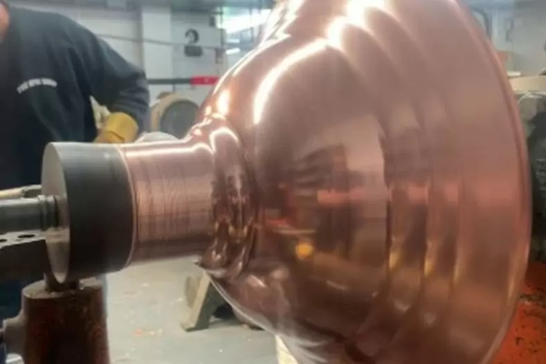
Figure 2-37 illustrates a coreless expansion spinning method to create spherical components with a bottom waist. The blank is positioned on the flange of the spinning machine spindle, secured by a tailstock centering pin. The tailstock pin remains stationary while the spindle rotates the tray and blank. A swing arm equipped with two spinning wheels executes the radial expansion through slow oscillatory motion, enabling the formation of spherical, drum-like aluminum, copper, or enameled components.
Forming Concave and Convex Components
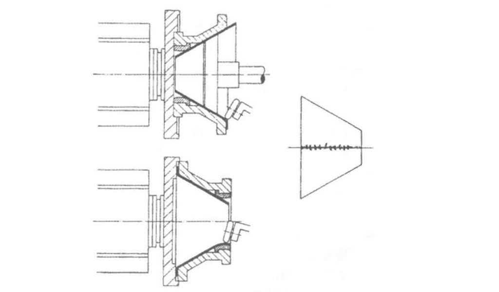
When forming parts such as high-pressure switch covers, fan collectors, or aircraft engine cowls, two spinning schemes can be employed. The first scheme utilizes a combination of internal and external spinning processes. The initial step involves placing a circular blank with a large central hole on a support ring and clamping it with an angular cross-section pressure ring. As the blank rotates, successive internal spinning operations progressively deform the material to conform to the internal contour of the mandrel. The second stage entails removing the pressure ring and applying a tailstock block shaped to match the previously formed profile for subsequent external spinning, yielding the final desired component.
Conversely, the second scheme employs two mandrels and two external spinning processes, where the first step utilizes a convex mandrel for multiple pulls to achieve a specific shape. The partially formed component is then inverted onto a new mandrel for further shaping, ultimately producing the required part.
In summary, the first scheme is characterized by a single set of mandrel and blank clamping, resulting in higher efficiency and lower costs, although it is limited to larger internal convex dimensions. The second scheme, while less efficient and more costly due to the need for two sets of tooling and blank handling, offers greater flexibility in processing various internal convex forms.
The Shapes Achieved Of Metal Spinning Parts
Simple shapes are easy to make in less time. But for complex shapes, it requires more time because it increases steps as per the block shape.
In addition to metal spinning, Be-cu.com also offers in-house tooling, welding, abrasive polishing and hydroforming, helping to drive down your costs and streamline production. Quicker turnaround times and lower costs are two of the most attractive advantages of metal spinning. The ability to form very thick components and large diameters with uniformity and high quality at low and high quantities, are more appealing reasons to consider metal spinning.To find out if metal spinning would be beneficial for your application or end product, contact us today.
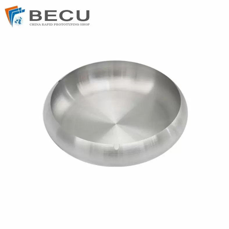
- Domed
- Flanged
- Domed with flange
- Dished
- Semi elliptical
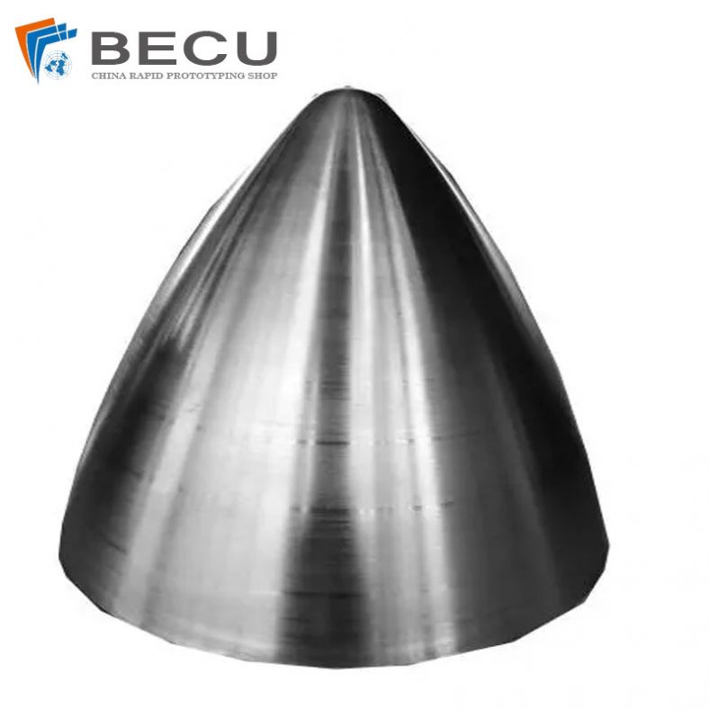
- Hemisphere
- Flanged, dished and flued
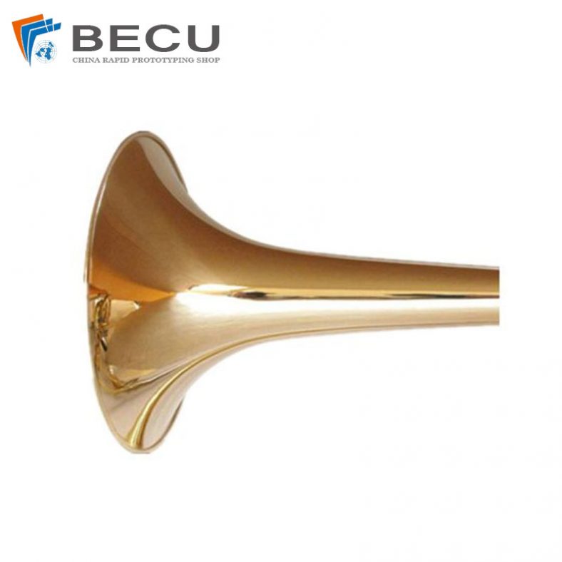
- Trumpet
The Detail Of BE-CU Metal Spinning Company
At Be-cu.com, we use a variety of materials for metal spinning such as cold rolled steel, hot rolled steel, aluminum spinning, stainless steel spinning, brass, copper spinning and exotic metals such as titanium and inconel. Be-cu Metal Spinning Section specializes in the forming of stainless steel. With our automated metal spinning lathes and the capabilities of our deep drawing, stamping and welding equipment, our ability to form your part to your specifications and within your budget are realistic. Be-cu Metal Spun Company has over 30 years of metal forming experience and has used the large metal spinning technology for a variety of industries such as aerospace, automotive, military, ordnance, plastics, lighting, pharmaceuticals, dairy, etc…
We have engineers on staff with metal spinning expertise to help guide you on designing a custom part and choose the optimal process to produce high quality spun parts at a competitive and affordable price. Tooling is custom made to form parts to your configuration.