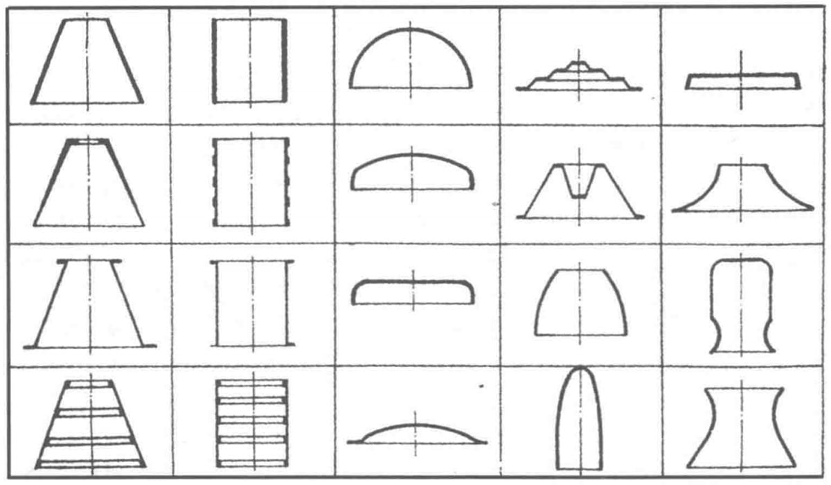
The structure of spun workpieces should be axially symmetric hollow thin-walled rotating bodies. With the development of spinning technology, the shapes of spin-formed products have become increasingly diverse. As shown in Figure 1-14, the shapes of spun products can be categorized into four types: conical, cylindrical, curved, and composite. Each of these can include various structural elements, such as:
- Wall thickness that remains constant or varies uniformly along the generatrix.
- A generatrix that can be straight or curved, with possible local grooves.
- Inner surfaces that may have or lack convex ring ribs.
- Heads that can be pointed, flat, rounded, or bi-directional cones.
- Ends that can have flange protrusions, lack flanges, have rolled edges, tapering closures, or rounded expansions.
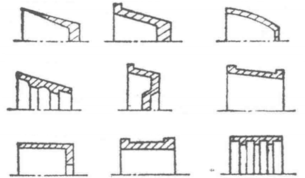
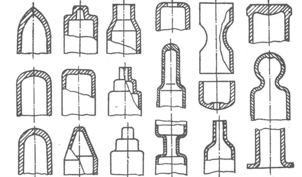
The variations in wall thickness, flange shapes, and internal ribs of spin-formed workpieces are illustrated in Figure 1-15. The end shapes of spun pipes are shown in Figure 1-16.
The shapes of various spun workpieces and their corresponding blank shapes are listed in Tables 1-15 to 1-18. The symbols in the tables represent: ddd — blank inner diameter, dFd_FdF — blank outer diameter, dnd_ndn — blank flange diameter, did_idi — finished diameter, dwd_wdw — finished flange diameter, SpS_pSp — blank thickness, SwS_wSw — blank flange thickness, SwS_wSw — finished end wall thickness, SbS_bSb — finished bottom thickness, and SwS_wSw — finished wall thickness.
Combination of Conventional and Power Spinning
Production practices have shown that relying solely on spinning as a processing method to form workpieces often leads to significant limitations. However, combining conventional spinning with power spinning, as well as their integration with other forming processes, can greatly expand their application range and often prove to be more economical. The following outlines several combined application scenarios.
The combination of conventional and power spinning can be categorized into four methods:
(1) Conventional Spinning followed by Power Spinning.
The process begins with conventional spinning to prepare the blank for power spinning. The workpiece’s shaping primarily relies on power spinning. This is a common scenario, as seen in the examples in Chapter 7. When using the composite spinning wheel shown in Figure 5-84, both conventional and power spinning are employed in a single pass. This method is suitable when the ratio of blank diameter to workpiece diameter is less than 1.4, particularly for aluminum blanks, which can be directly spun into cylindrical parts.
(2) Power Spinning followed by Conventional Spinning.
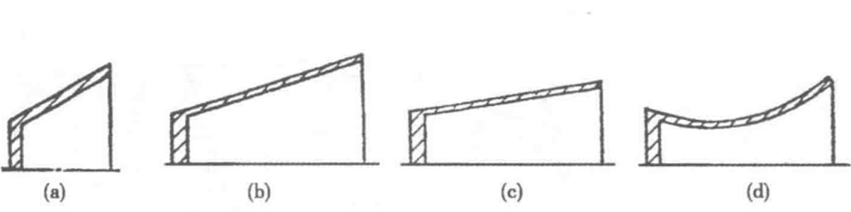
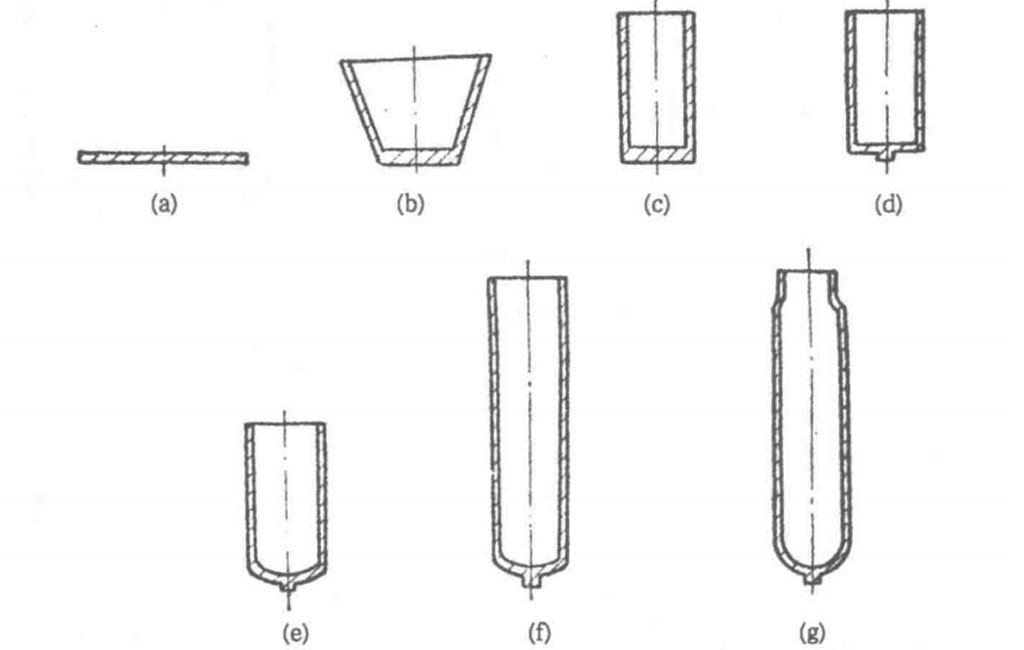
The process starts with power spinning, followed by conventional spinning to complete local shaping or calibration tasks that are difficult to achieve with power spinning alone. For example, the tungsten alloy rocket nozzle produced by General Dynamics (Figure 1-17) follows this processing scheme.
The original tungsten alloy powder is sintered and pressed (or rolled) into tungsten sheets, which are then cut into circular blanks. The process steps are as follows: First, the core mold is preheated to 500–550°C; the blank is placed on the core mold and heated with an oxyacetylene torch to 1000–1165°C.
In the second step, the first pass (Figure a) uses power spinning to form a conical piece with a 60° cone angle (reduction of 50%); in the third step, the second pass (Figure b) further forms a conical piece with a 30° cone angle (reduction of 48%), achieving a total thinning rate of 75%. The fourth step involves trimming and cleaning the surface oxide layer with a mixture of high-pressure aluminum oxide powder and water.
The fifth step is annealing (heating in dry hydrogen to 950°C for 1 hour) to eliminate internal stress. The sixth step involves heating to the same temperature again, followed by two passes of conventional spinning; the first pass (Figure c) reduces the cone angle further, and the second pass (Figure d) completes the final shaping.
(3) Conventional Spinning – Power Spinning – Conventional Spinning.
This method combines the previous two approaches and is suitable for complex-shaped components. Typically, conventional spinning is used for pre-forming to provide a prefabricated blank, followed by power spinning to accomplish most of the shaping, and finally, conventional spinning to complete the workpiece shaping. Figure 1-18 illustrates this method of manufacturing a rocket nozzle from a flat blank.
(4) Power Spinning – Conventional Spinning – Power Spinning.
An example of this combined application is in the spinning of a satellite nose cone (example 8, Figure 4-48). The spun material is 430 stainless steel, characterized by a spherical bottom at the small end, a short cylindrical section at the opening, and a conical middle. The blank is a circular plate with a punched spherical cavity. The main steps include: the first pass is shear spinning I (α = 25°), the second pass is trimming followed by conventional spinning to finish the cylindrical section, and the third pass is shear spinning II (α = 8°30′) after annealing.
Combined Application of Spinning and Cold Stamping (Molding)
The combined use of spinning and cold stamping mainly aims to leverage their respective advantages for economical workpiece forming.
(1) Power Spinning Combined with Stamping Deep Drawing.
This combined approach reduces the number of processing steps and saves on mold quantities and costs compared to using simple conventional stamping deep drawing. The resulting workpieces have more uniform wall thickness, and the material properties are improved during power spinning. An example is shown in Figure 1-19, where the blank is a sheet that is first formed into a conical piece with a constant wall thickness and a half cone angle of 17° (Figure a) using shear spinning. The cone angle can be determined based on the material’s spinnability; smaller angles result in fewer subsequent drawing steps. In this case, two drawing steps achieve the final cylindrical workpiece dimensions (see Figures b and c; Figure d illustrates the working diagram of the re-forming mold). The thinning rate from power spinning is 70%, with the first drawing coefficient being 0.56 and the second being 0.67.
(2) Deep Drawing and Conventional Spinning Edge Forming.
An example of this combination is illustrated in Figure 6-125, which shows the spinning forming of end caps. The central spherical cavity of the end cap is formed using a female die fixed to the piston rod of the tightening oil cylinder and a male die fixed to the spindle head, with the pressure determined by the forming area, material, and wall thickness. This is followed by conventional edge forming (flanging). Another example is illustrated in Figure 7-32, which shows the formation of a bottle bottom with a recessed shape, where the bottom is first stamped and then subjected to edge spinning.
(3) Deep Drawing Combined with Power Spinning.
In this process, deep drawing is used for high efficiency, with power spinning serving as the final forming step. This not only shortens processing time and reduces mold costs, but also improves workpiece accuracy (see processing examples 89, 90, 93, and 97, etc.). Any wall thickness discrepancies caused during drawing can be minimized through spinning.
(4) Power Spinning – Deep Drawing – Power Spinning.
This combined method offers the advantage of further reducing stamping mold costs, but requires a longer processing time, making it suitable only for smaller batches. To compensate for this, higher rotational speeds and feed rates can be used in the second pass of power spinning compared to the first.
Figure 1-20 provides an example of using stainless steel sheets to manufacture a cylindrical part with a base. Figure 1-21 illustrates the process of producing a seamless rocket casing from flat blanks using this method. Figure 4-32 also uses this method for processing items like fire extinguisher housings. For producing long and slender parts in batches, deep drawing is recommended due to its high production efficiency; for single or small batch production of short, thick parts, power spinning is preferred to save on large stamping mold costs.
Combined Application of Spinning with Other Bulk Forming Processes
For complex-shaped workpieces, combining spinning with other bulk forming processes can achieve the desired shaping. For example, various methods such as explosive forming, hot punching, cold drawing, and hot extrusion can be used to produce spun blanks, which are then further processed through machining and spinning. An example is shown in the process flow of aluminum fire extinguisher cylinders in Section 3.7, Figure 3-126, where aluminum rods are extruded and aluminum sheets are stamped to create blanks. The former undergoes hot closing spinning and machining, while the latter is completed through two or three rounds of thinning spinning and hot closing spinning, both representing instances of this combined application.
Additionally, as illustrated in Figure 2-86, the joint application of spinning and drawing utilizes the wall-reducing capability of spinning and the diameter-reducing feature of drawing to create various cross-sectional shapes and thin, elongated irregular pipes. This represents a case of combined spinning and drawing in a single pass. However, the LXC40/150 dual-purpose spinning and drawing machine shown in Figure 5-128 employs a stepwise process for the combined application of spinning and drawing.
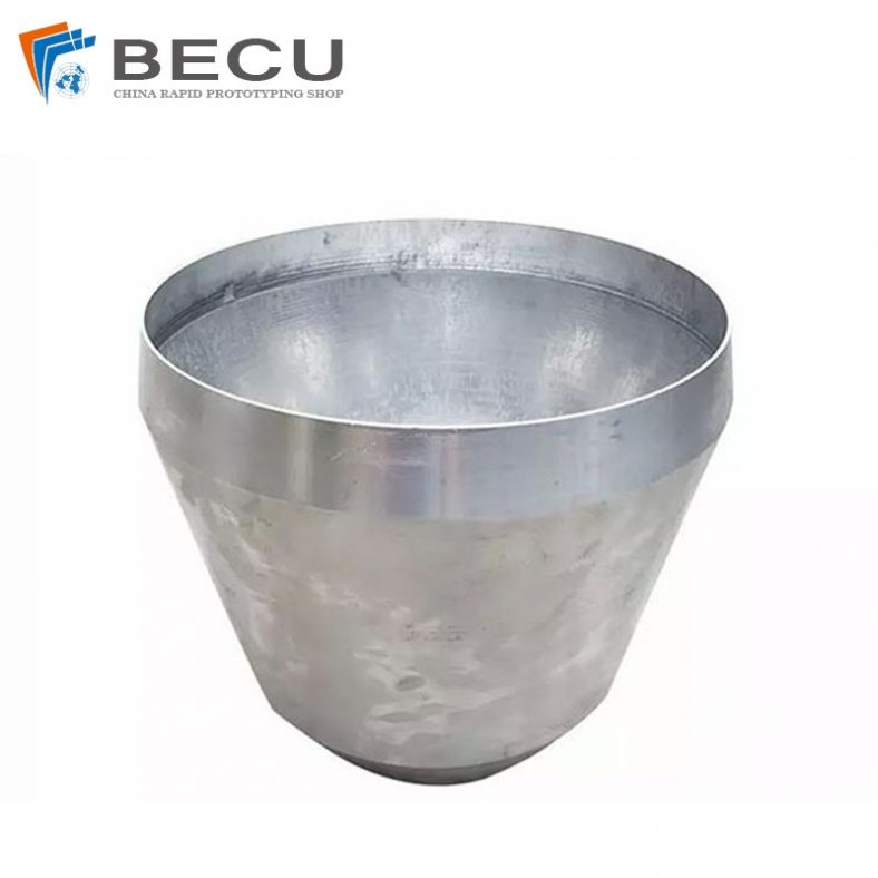
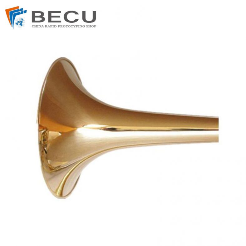
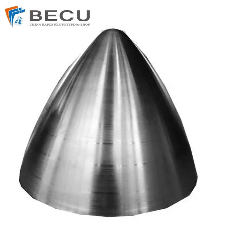
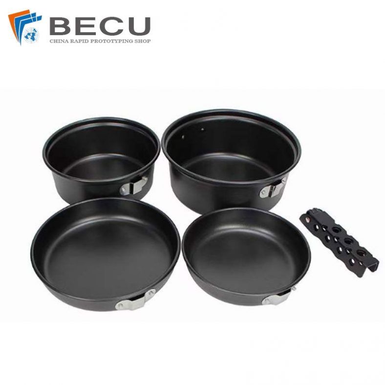
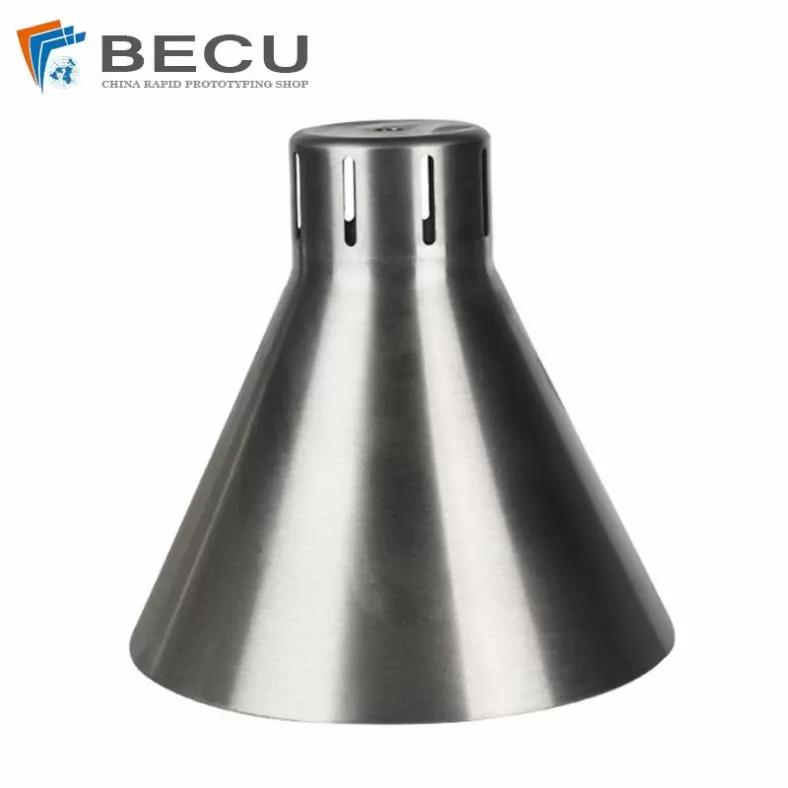
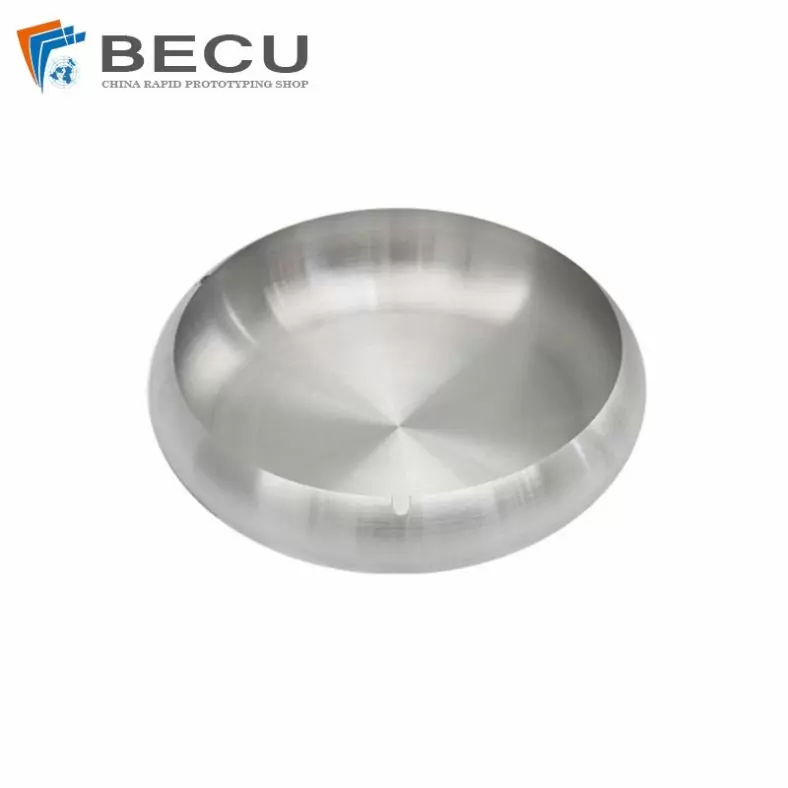
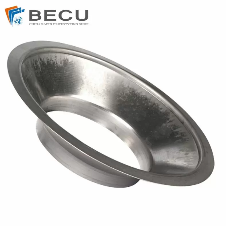
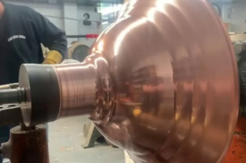
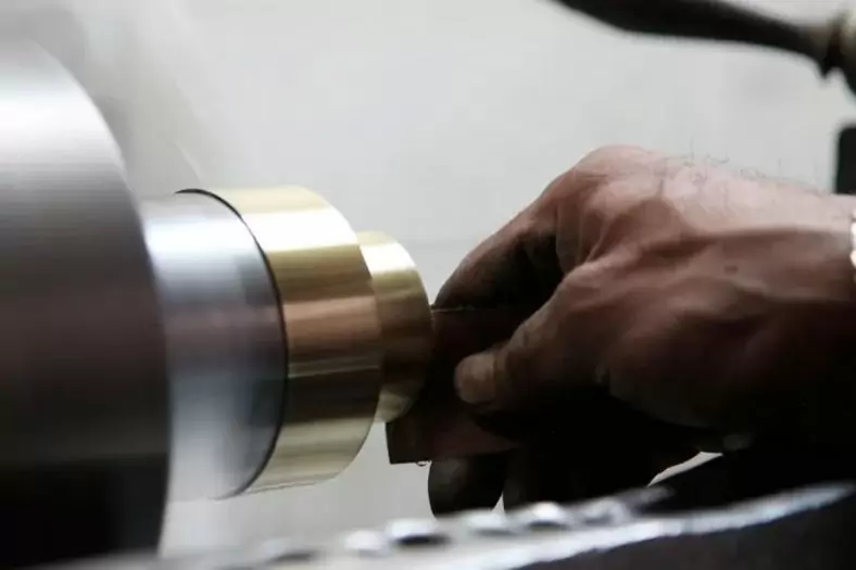
The Shapes Achieved Of Metal Spinning Parts
Simple shapes are easy to make in less time. But for complex shapes, it requires more time because it increases steps as per the block shape.
In addition to metal spinning, Be-cu.com also offers in-house tooling, welding, abrasive polishing and hydroforming, helping to drive down your costs and streamline production. Quicker turnaround times and lower costs are two of the most attractive advantages of metal spinning. The ability to form very thick components and large diameters with uniformity and high quality at low and high quantities, are more appealing reasons to consider metal spinning.To find out if metal spinning would be beneficial for your application or end product, contact us today.
- Domed
- Flanged
- Domed with flange
- Dished
- Semi elliptical
- Hemisphere
- Flanged, dished and flued
- Trumpet
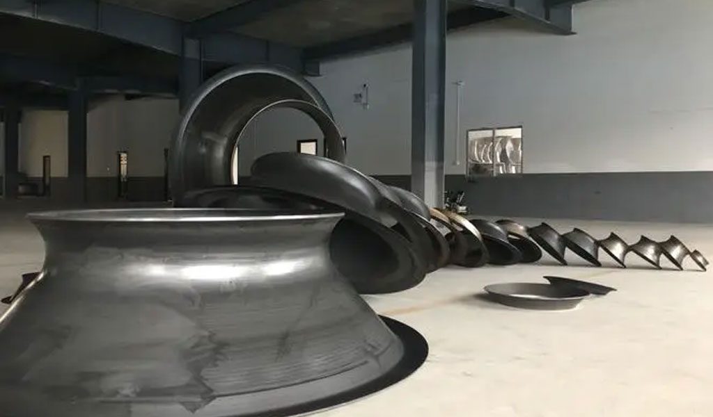
The Detail Of BE-CU Metal Spinning Company
At Be-cu.com, we use a variety of materials for metal spinning such as cold rolled steel, hot rolled steel, aluminum spinning, stainless steel spinning, brass, copper spinning and exotic metals such as titanium and inconel. Be-cu Metal Spinning Section specializes in the forming of stainless steel. With our automated metal spinning lathes and the capabilities of our deep drawing, stamping and welding equipment, our ability to form your part to your specifications and within your budget are realistic. Be-cu Metal Spun Company has over 30 years of metal forming experience and has used the large metal spinning technology for a variety of industries such as aerospace, automotive, military, ordnance, plastics, lighting, pharmaceuticals, dairy, etc…
We have engineers on staff with metal spinning expertise to help guide you on designing a custom part and choose the optimal process to produce high quality spun parts at a competitive and affordable price. Tooling is custom made to form parts to your configuration.