
Shaft keys are fundamental mechanical components used to connect rotating machine elements, such as gears, pulleys, sprockets, or couplings, to a shaft, ensuring the transmission of torque and preventing relative rotation between the shaft and the attached component. The keyed joint, comprising the key, keyway (a slot in the shaft), and keyseat (a slot in the hub of the rotating element), forms a robust mechanical interface critical to power transmission in machinery. Shaft keys are employed across industries, from automotive and aerospace to manufacturing and marine applications, due to their simplicity, cost-effectiveness, and reliability.
The design and selection of shaft keys involve multiple considerations, including the type of key, its dimensions, material properties, load requirements, and environmental conditions. Standards such as BS 4235, ASME B17.1, and DIN 6892 provide guidelines for key dimensions and tolerances, while material selection is governed by factors like strength, corrosion resistance, and compatibility with the shaft and hub materials. This article provides a comprehensive exploration of shaft key types, standardized size charts, material grades, design formulas, and calculation methods, supported by detailed tables for practical reference.
Historical Context and Evolution of Shaft Keys
The use of shaft keys dates back to the Industrial Revolution, when the need for reliable power transmission in steam engines and early machinery necessitated robust methods to secure rotating components. Early keys were often hand-forged from wrought iron or low-carbon steel, with rudimentary shapes like square or rectangular profiles. These primitive designs, while functional, lacked standardization, leading to inconsistencies in performance and frequent failures under high loads.
The 19th century saw advancements in machining technology, enabling more precise keyway cutting and key fabrication. By the early 20th century, standards organizations like the British Standards Institution (BSI) and the American Society of Mechanical Engineers (ASME) began developing standardized dimensions for keys and keyways, such as BS 46 (predecessor to BS 4235) and ASME B17.1. These standards facilitated interchangeability and improved reliability in mechanical systems. The introduction of alloy steels and heat treatment processes further enhanced key performance, allowing them to withstand higher torques and fatigue loads.
In the modern era, shaft keys have evolved to accommodate specialized applications, with materials like stainless steel, brass, and even non-metallic composites used in corrosive or lightweight environments. Advanced manufacturing techniques, such as CNC machining and electrical discharge machining (EDM), have enabled the production of complex key types, like Woodruff and spline keys, with tight tolerances. The integration of computational tools, such as finite element analysis (FEA), has also refined key design, optimizing stress distribution and minimizing failure risks.
Types of Shaft Keys
Shaft keys are classified based on their shape, installation method, and application. The following subsections detail the primary types of shaft keys, their characteristics, and their uses.
Parallel Keys
Parallel keys, also known as straight keys, are the most common type of shaft key due to their simplicity and versatility. They have a uniform cross-section, typically square or rectangular, and are inserted into keyways machined in both the shaft and the hub. Parallel keys are side-fitting, meaning they primarily transmit torque through shear and compressive forces along their side faces.
- Square Keys: These have equal width and height, suitable for shafts with diameters ranging from 0.25 to 1.0 inches (6 to 25 mm). Square keys are used in applications requiring high torque transmission, as their symmetric cross-section distributes stresses evenly.
- Rectangular Keys: Wider than they are tall, rectangular keys are employed for larger shafts (1 to 20 inches or 25 to 500 mm in diameter). They transmit higher torque without requiring deeper keyways, reducing stress concentrations in the shaft.
Parallel keys are inexpensive, readily available in standard sizes (key stock), and easy to install. However, they may loosen in vibrating or reversing applications unless secured with setscrews or other retainers. Standards like BS 4235-1 and ASME B17.1 specify dimensions and tolerances for parallel keys.
Woodruff Keys
Woodruff keys are semicircular keys that fit into a curved slot milled in the shaft, with the flat top aligned parallel to the shaft axis. Their semicircular shape makes them captive, preventing axial movement during operation, which is advantageous in high-speed applications. Woodruff keys are typically used for shafts with diameters up to 6.5 inches (165 mm) and are specified by standards like ASME B17.2.
The primary advantage of Woodruff keys is their ability to improve concentricity, making them ideal for high-speed machinery, such as turbines and compressors. They also eliminate the need for keyways near stress concentration areas, like shaft shoulders. However, their installation requires specialized milling tools, increasing manufacturing costs. Woodruff keys are commonly made from key steel, stainless steel, or aluminum for lightweight applications.
Taper Keys
Taper keys have a tapered profile, typically with a 1:100 taper, allowing them to be driven into the keyway to create a tight fit. They are used in applications requiring frequent assembly and disassembly, as the taper facilitates easy removal. Taper keys include:
- Gib-Head Keys: These have a protruding head that aids in removal using a wedge or puller. Gib-head keys are used in heavy machinery, such as crushers and rolling mills, but require sufficient axial clearance for head access.
- Plain Taper Keys: Lacking a head, these are simpler and used in compact assemblies where space is limited.
Taper keys provide a secure fit through frictional forces, reducing the risk of slippage under reversing loads. However, their installation can induce radial stresses in the hub, potentially causing splitting in brittle materials.
Saddle Keys
Saddle keys are fitted into a keyway in the hub but rest on the shaft’s surface, either flat or curved, transmitting torque through friction rather than shear. They are less common due to their lower torque capacity and are typically used in low-power applications, such as light machinery or temporary assemblies.
- Flat Saddle Keys: These rest on a flattened shaft surface, relying on friction for torque transmission.
- Hollow Saddle Keys: These conform to the shaft’s curvature, providing a larger contact area for improved frictional grip.
Saddle keys are easy to install but prone to slippage under high loads, limiting their use in critical applications.
Tangent Keys
Tangent keys consist of two keys installed at 90 degrees to each other, each contacting the shaft tangentially. They are used in heavy-duty applications, such as large turbines and marine propeller shafts, where high torque and bidirectional loading are present. Tangent keys distribute loads over a larger area, reducing stress concentrations, but their complex installation and higher cost restrict their use to specialized machinery.
Round Keys
Round keys, or pin keys, are cylindrical pins inserted through aligned holes in the shaft and hub. They are used in small-diameter shafts or applications where traditional keyways are impractical, such as in couplings. Round keys are simple and cost-effective but have limited torque capacity due to their small shear area.
Spline Keys
Splines are not true keys but serve a similar function, consisting of multiple teeth or ridges machined into the shaft and hub. They provide superior torque transmission and alignment compared to single keys, making them suitable for high-power, high-precision applications, like automotive transmissions and aerospace actuators. Splines are classified as straight or involute, with involute splines offering better load distribution due to their curved tooth profile.
Size Charts and Standards
Shaft key dimensions are standardized to ensure interchangeability and compatibility across applications. The following subsections present detailed size charts for common key types, based on standards like BS 4235, ASME B17.1, and DIN 6892.
Parallel Key Size Chart
Parallel keys are specified by their width, height, and length, which are functions of the shaft diameter. The following table provides metric dimensions for parallel keys per BS 4235-1:1972.
Parallel Key Size Chart (Metric, BS 4235-1:1972)
| Shaft Diameter (mm) | Key Width (mm) | Key Height (mm) | Keyway Depth (Shaft, mm) | Keyway Depth (Hub, mm) | Tolerance (mm) |
|---|---|---|---|---|---|
| 6–8 | 2 | 2 | 1.2 | 1.0 | ±0.012 |
| 8–10 | 3 | 3 | 1.8 | 1.4 | ±0.012 |
| 10–12 | 4 | 4 | 2.5 | 1.8 | ±0.015 |
| 12–17 | 5 | 5 | 3.0 | 2.3 | ±0.015 |
| 17–22 | 6 | 6 | 3.5 | 2.8 | ±0.018 |
| 22–30 | 8 | 7 | 4.0 | 3.3 | ±0.018 |
| 30–38 | 10 | 8 | 5.0 | 3.3 | ±0.022 |
| 38–44 | 12 | 8 | 5.0 | 3.3 | ±0.022 |
| 44–50 | 14 | 9 | 5.5 | 3.8 | ±0.022 |
| 50–58 | 16 | 10 | 6.0 | 4.3 | ±0.027 |
| 58–65 | 18 | 11 | 7.0 | 4.4 | ±0.027 |
| 65–75 | 20 | 12 | 7.5 | 4.9 | ±0.027 |
| 75–85 | 22 | 14 | 9.0 | 5.4 | ±0.033 |
| 85–95 | 25 | 14 | 9.0 | 5.4 | ±0.033 |
| 95–110 | 28 | 16 | 10.0 | 6.4 | ±0.033 |
| 110–130 | 32 | 18 | 11.0 | 7.4 | ±0.039 |
Tolerances apply to key width and height; keyway tolerances may vary per standard.
For imperial units, ASME B17.1-1967 provides similar specifications, as shown below.
Parallel Key Size Chart (Imperial, ASME B17.1-1967)
| Shaft Diameter (in) | Key Width (in) | Key Height (in) | Keyway Depth (Shaft, in) | Keyway Depth (Hub, in) | Tolerance (in) |
|---|---|---|---|---|---|
| 0.25–0.3125 | 0.0625 | 0.0625 | 0.0375 | 0.025 | ±0.0005 |
| 0.3125–0.375 | 0.09375 | 0.09375 | 0.05625 | 0.0375 | ±0.0005 |
| 0.375–0.5 | 0.125 | 0.125 | 0.075 | 0.05 | ±0.0006 |
| 0.5–0.625 | 0.15625 | 0.15625 | 0.09375 | 0.0625 | ±0.0006 |
| 0.625–0.875 | 0.1875 | 0.1875 | 0.1125 | 0.075 | ±0.0007 |
| 0.875–1.125 | 0.25 | 0.25 | 0.15 | 0.1 | ±0.0007 |
| 1.125–1.375 | 0.3125 | 0.3125 | 0.1875 | 0.125 | ±0.0008 |
| 1.375–1.75 | 0.375 | 0.375 | 0.225 | 0.15 | ±0.0008 |
| 1.75–2.25 | 0.5 | 0.5 | 0.3 | 0.2 | ±0.0010 |
| 2.25–2.75 | 0.625 | 0.625 | 0.375 | 0.25 | ±0.0010 |
| 2.75–3.25 | 0.75 | 0.75 | 0.45 | 0.3 | ±0.0012 |
| 3.25–3.75 | 0.875 | 0.875 | 0.525 | 0.35 | ±0.0012 |
| 3.75–4.5 | 1.0 | 1.0 | 0.6 | 0.4 | ±0.0015 |
Key length varies based on application, typically 1.5 to 2 times the shaft diameter.
Tolerances are for key dimensions; keyway tolerances depend on machining precision.
Woodruff Key Size Chart
Woodruff keys are specified by their diameter and width, with the key number indicating the nominal size. The following table provides dimensions per ASME B17.2-1967.
Woodruff Key Size Chart (Imperial, ASME B17.2-1967)
| Key Number | Nominal Diameter (in) | Width (in) | Height (in) | Keyway Depth (in) | Shaft Diameter Range (in) |
|---|---|---|---|---|---|
| 204 | 0.5 | 0.0625 | 0.194 | 0.104 | 0.375–0.5 |
| 305 | 0.625 | 0.09375 | 0.241 | 0.129 | 0.5–0.625 |
| 406 | 0.75 | 0.125 | 0.288 | 0.154 | 0.625–0.75 |
| 608 | 1.0 | 0.1875 | 0.382 | 0.204 | 0.875–1.0 |
| 810 | 1.25 | 0.25 | 0.476 | 0.254 | 1.125–1.25 |
| 1012 | 1.5 | 0.3125 | 0.570 | 0.304 | 1.375–1.5 |
| 1216 | 2.0 | 0.375 | 0.758 | 0.404 | 1.75–2.0 |
Key number format: First digit(s) indicate width (in 1/32 in.), last digit(s) indicate diameter (in 1/8 in.).
Metric equivalents are available per ISO standards.
Taper Key Size Chart
Taper keys follow similar width and height specifications as parallel keys but include a taper angle. The following table provides dimensions for gib-head taper keys per ASME B17.1.
Taper Key Size Chart (Imperial, ASME B17.1)
| Shaft Diameter (in) | Key Width (in) | Key Height (in) | Taper (in/ft) | Head Height (in) | Tolerance (in) |
|---|---|---|---|---|---|
| 0.5–0.75 | 0.125 | 0.125 | 1:100 | 0.1875 | ±0.0006 |
| 0.75–1.0 | 0.1875 | 0.1875 | 1:100 | 0.28125 | ±0.0007 |
| 1.0–1.5 | 0.25 | 0.25 | 1:100 | 0.375 | ±0.0007 |
| 1.5–2.0 | 0.375 | 0.375 | 1:100 | 0.5625 | ±0.0008 |
| 2.0–2.5 | 0.5 | 0.5 | 1:100 | 0.75 | ±0.0010 |
| 2.5–3.0 | 0.625 | 0.625 | 1:100 | 0.9375 | ±0.0010 |
Taper is typically 1:100 (1 mm per 100 mm length).
Head height is approximately 1.5 times the key height.
Material Grades for Shaft Keys
The material selection for shaft keys is critical to ensure adequate strength, durability, and compatibility with the shaft and hub. Common materials include carbon steels, alloy steels, stainless steels, and non-ferrous alloys, each suited to specific operating conditions.
Carbon and Alloy Steels
Carbon steels, such as AISI 1045 (EN8 or C45), are widely used for shaft keys due to their balance of strength, toughness, and machinability. They have carbon content ranging from 0.25% to 0.60%, with ultimate tensile strengths (UTS) of 600–800 MPa. Heat treatment, such as quenching and tempering, can enhance hardness and wear resistance.
Alloy steels, like AISI 4140 or 4340, offer higher strength (UTS up to 1000 MPa) and fatigue resistance, making them suitable for high-torque applications. They are often used in heavy machinery and aerospace systems.
Stainless Steels
Stainless steels, such as AISI 316 and 303, are used in corrosive environments, such as food processing or marine applications. AISI 316 offers excellent corrosion resistance but lower strength (UTS ~500 MPa), while AISI 430 provides higher strength (UTS ~700 MPa) in mildly corrosive conditions.
Non-Ferrous Alloys
Non-ferrous alloys, including aluminum, brass, and bronze, are used in lightweight or specialized applications. Brass (UNS C36000) and bronze (UNS C93200) are common in marine environments due to their corrosion resistance, though their lower strength (UTS 300–500 MPa) limits their use to low-torque applications.
Material Properties Table
| Material | Grade | UTS (MPa) | Yield Strength (MPa) | Applications | Notes |
|---|---|---|---|---|---|
| Carbon Steel | AISI 1045 | 600–800 | 350–450 | General machinery | Good machinability, heat-treatable |
| Alloy Steel | AISI 4140 | 850–1000 | 600–750 | Heavy machinery, aerospace | High strength, fatigue-resistant |
| Stainless Steel | AISI 316 | 500–600 | 200–300 | Food processing, marine | Excellent corrosion resistance |
| Stainless Steel | AISI 430 | 600–700 | 400–500 | Mildly corrosive environments | Moderate corrosion resistance |
| Brass | UNS C36000 | 300–400 | 150–200 | Marine, low-torque applications | Corrosion-resistant, lightweight |
| Bronze | UNS C93200 | 350–450 | 200–250 | Marine propellers | Good wear resistance |
Notes:
- UTS and yield strength values are approximate and depend on heat treatment.
- Material selection should consider shaft and hub material compatibility to avoid galvanic corrosion.
Design Formulas and Calculations
The design of shaft keys involves calculating stresses, torque capacity, and key dimensions to ensure the keyed joint can withstand applied loads without failure. The following subsections outline key design formulas and calculation methods, incorporating safety factors and failure theories.
Torque Transmission
The torque T transmitted by a key is given by:
T=F⋅r
where:
- F F F is the shear force on the key (N),
- r r r is the radius of the shaft (m).
The shear force F F F is:
F=τs⋅As
where:
- τs τs is the permissible shear stress (Pa),
- As is the shear area of the key (m²).
For a rectangular key, the shear area is:
As=L⋅W
where:
- L is the key length (m),
- W is the key width (m).
Shear Stress
The permissible shear stress τs \tau_s τs is calculated using the material’s yield strength Sy S_y Sy and a factor of safety Fs F_s Fs:
τs=Sy/2⋅Fs
For carbon steels, Sy S_y Sy typically ranges from 350 to 600 MPa, and Fs F_s Fs is often 2.5–3.0 for static loads, higher for dynamic or reversing loads.
Compressive Stress
Compressive stress σc \sigma_c σc on the key’s side face is:
σc=F/Ac
where:
- Ac=L⋅H H Ac=L⋅H is the compressive area (m²),
- H H H is the key height (m).
The permissible compressive stress is:
σc≤Sy/Fa
Key Length Calculation
To determine the required key length L L L, rearrange the torque equation:
L=T/τs⋅W⋅r
For a given torque and material, the key length must be sufficient to keep stresses within permissible limits. Standards recommend L L L be 1.5–2 times the shaft diameter.
Service Factors
Service factors adjust calculations for operating conditions, such as shock loads, vibration, or reversing torque. The service factor Ks K_s Ks is:
Ks=Kd⋅Ka⋅Km⋅Kf⋅Kw
where:
- Kd K_d Kd: Design factor (1.0–1.5, based on precision),
- Ka K_a Ka: Application factor (1.0 for steady loads, up to 2.0 for shock loads),
- Km K_m Km: Load distribution factor (1.0–1.2, for misalignment),
- Kf K_f Kf: Fatigue life factor (1.0–1.5, for cyclic loads),
- Kw K_w Kw: Wear life factor (1.0–1.2, for splines or high wear).
The adjusted torque is:
Tadj=T⋅Ks
Example Calculation
Consider a 50 mm diameter shaft transmitting 10 kW at 1000 RPM, using a rectangular key (AISI 1045, Sy=450 S_y = 450 Sy=450 MPa, Fs=2.5 F_s = 2.5 Fs=2.5).
- Torque:
T=P⋅602π⋅N=10000⋅602π⋅1000=95.49 Nm 60}{2 \pi \cdot 1000} = 95.49 \, \text{Nm} T=2π⋅NP⋅60=2π⋅100010000⋅60=95.49Nm
- Shear Stress:
τs=450⋅1062⋅2.5=90 MPa \tau_s = \frac{450 \cdot 10^6}{2 \cdot 2.5} = 90 \, \text{MPa} τs=2⋅2.5450⋅106=90MPa
- Key Dimensions (per BS 4235-1):
- Shaft diameter: 50 mm → Key: 16 mm (W) × 10 mm (H).
- Shear area: As=L⋅16⋅10−3
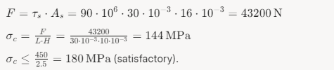
- Key Length:
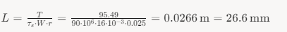
Select L=30 mm(standard length).
- Compressive Stress:
Practical Applications and Considerations
Shaft keys are integral to numerous applications, each presenting unique challenges:
- Automotive: Transmission shafts use spline keys for high torque and alignment precision.
- Marine: Propeller shafts employ bronze or stainless steel keys to resist corrosion.
- Aerospace: Lightweight aluminum or titanium keys are used in actuators to reduce weight.
- Industrial Machinery: Parallel keys dominate in conveyors, pumps, and gearboxes due to their versatility.
Key design must account for:
- Fatigue: Cyclic loads require higher safety factors and fatigue-resistant materials.
- Corrosion: Stainless steel or coatings mitigate corrosion in harsh environments.
- Alignment: Tight tolerances ensure concentricity and minimize vibration.
- Installation: Proper fitment prevents slippage or hub damage.
Advanced Analysis Techniques
Modern key design leverages computational tools to optimize performance:
- Finite Element Analysis (FEA): Models stress concentrations and deformations, critical for complex geometries like Woodruff keys.
- Fatigue Life Prediction: Software like ANSYS or SolidWorks simulates cyclic loading to estimate service life.
- CAD/CAM Integration: Enables precise keyway milling and key fabrication, reducing manufacturing variability.
Future Directions for Shaft Key Technology
Emerging trends include:
- Composite Keys: Carbon fiber or polymer-based keys for lightweight, corrosion-resistant applications.
- Additive Manufacturing: 3D printing enables custom keys with optimized geometries.
- Smart Materials: Shape-memory alloys for adaptive key systems in variable-load conditions.
- Sustainability: Recyclable materials and energy-efficient manufacturing processes.
Conclusion
Shaft keys are essential components in mechanical power transmission, offering a reliable, cost-effective means to connect rotating elements to shafts. Their design and selection require careful consideration of type, size, material, and load conditions, guided by standards and advanced calculations. This article has provided an exhaustive treatment of shaft key types, size charts, material grades, design formulas, and practical considerations, supported by detailed tables. As technology advances, shaft keys will evolve to meet the demands of increasingly complex and sustainable engineering systems, ensuring their continued relevance in the mechanical engineering landscape.

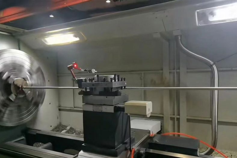
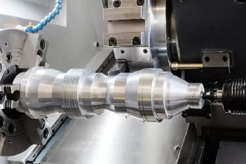
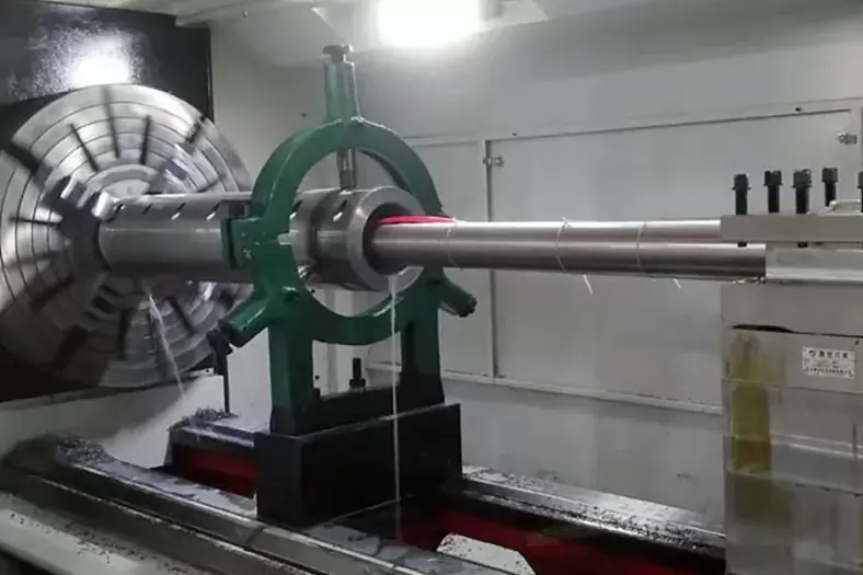
The Detail Of BE-CU Cnc Turning Company
Be-cu.com is an experienced precision CNC turning services supplier, manufacturer, exporter in China, has been specialized in offering best OEM CNC lathe services for superior quality low cost CNC turning parts, CNC lathe parts or high precision machined components with the operation of an impressive range of state-of-the-art turning machines, such as washers, bolts, shafts, rivets, spacers, sleeves, nipples, stainless steel fittings, pipe fittings, light fittings, wheel studs, etc. Our advanced CNC turning center routinely works with a wide variety of materials, ranging from copper, brass, stainless steel, carbon steel, aluminum, and titanium. We can always choose a suitable precision turning process to reach your requirements. Our custom cnc machining services ensure that our customers receive the highest quality CNC turned parts.
-
Restoration of Petroleum Splined Shafts through Supersonic Thermal Spray Coating
-

Large CNC Turning Inconel 625 Automobile Engine Camshafts
-
Precision Turning Solid Wood Dice
-
Custom Wood Chess Board, Sets And Pieces
-
Swiss Machining And Bending 304 Hand Sewing Needle For Textile Machinery
-
Automatic Swiss Turning Stainless Steel 316L U-bolt
-

4 Axis CNC Machining Titanium Grade 5 Mobile Phone Buttons
-
Precision Turning 20° Acrylic Downlight Reflector