
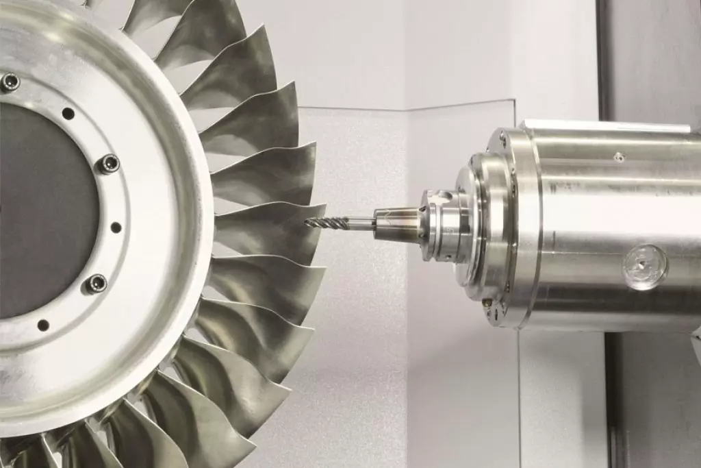
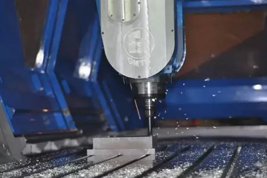
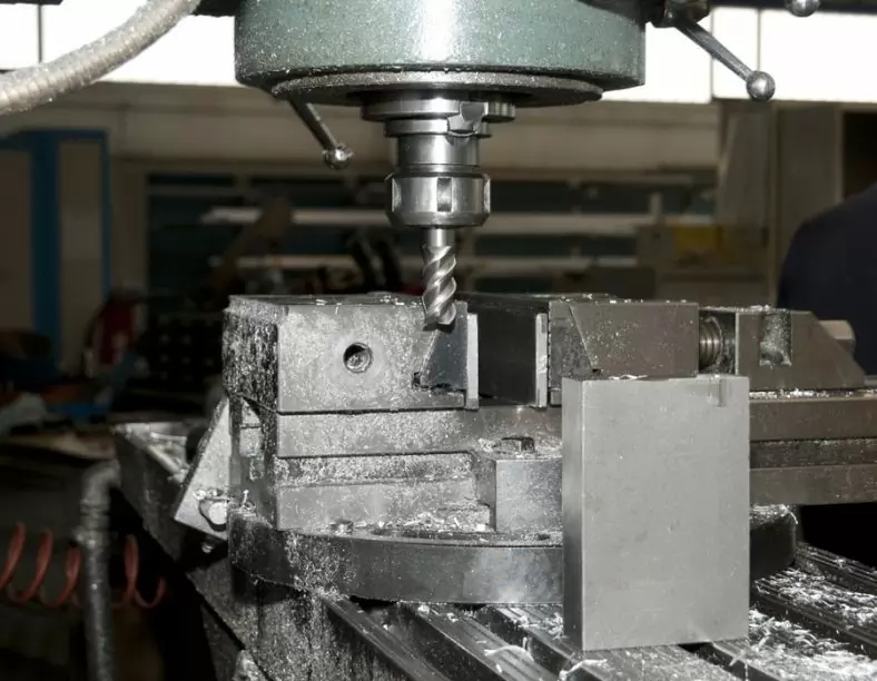
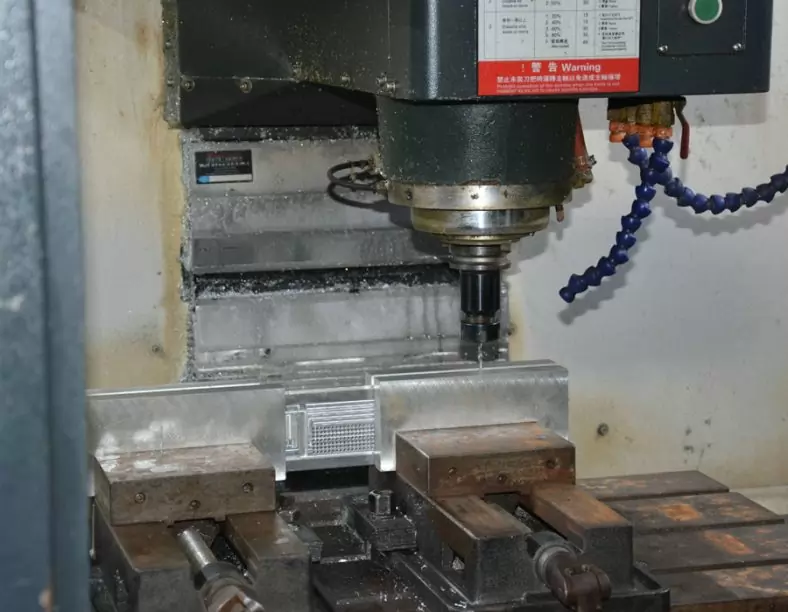
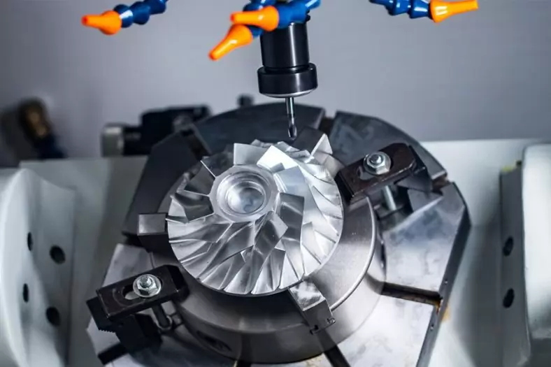
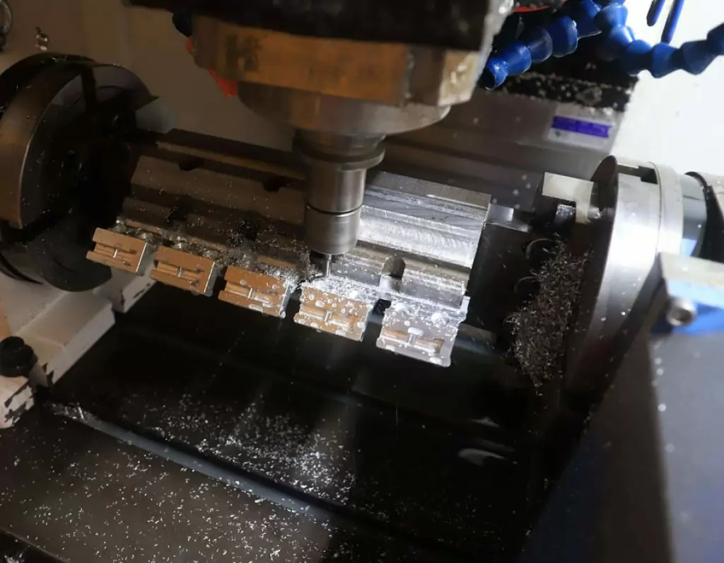
What Is Cnc Milling? Cnc Milling is to fix the blank, and use a high-speed rotating milling cutter to move on the blank to cut out the required shapes and features. Traditional milling is mostly used to mill simple shape features such as contours and grooves. CNC milling machines can process complex shapes and features. The milling and boring machining center can perform three-axis or multi-axis milling and cnc boring, which is used for cnc machining, molds, inspection tools, molds, thin-walled complex curved surfaces, artificial prostheses, blades, etc. When selecting the content of CNC milling, the advantages and key roles of CNC milling machine should be fully utilized.However, very accurate and versatile general-purpose milling machines have also been widely used in machine repair shops and tool and mold manufacturing. With a milling machine and an ordinary lathe in the workshop, various products with suitable dimensions can be processed.
The Difference Between Turning And Milling
Milling is a common metal cold machining method. The difference from turning is that in milling, the tool is driven by the spindle to rotate at a high speed, while the workpiece is relatively static; turning is used to process rotating parts, and the parts are passed through three grips. The disc is clamped on the main shaft of the machine tool and rotated at high speed, and then the turning tool is used to move the tool according to the generatrix of the revolving body to cut out the appearance of the product. The lathe can also process the inner hole, thread, biting, etc., the latter two are low-speed cnc machining.
Cnc Milling Definition
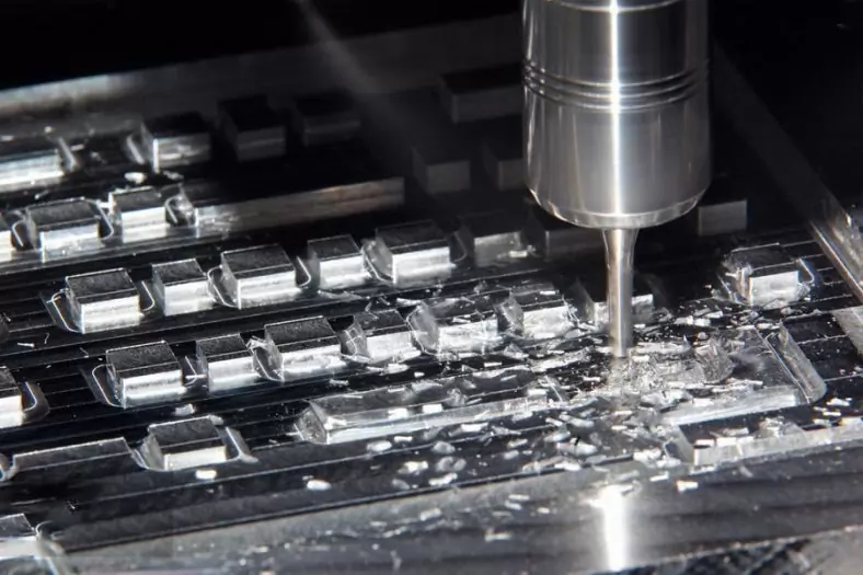
Cnc Milling is a basic method of machining. In this machining process, when the workpiece is fed in a direction perpendicular to the axis of the rotating tool, chips are formed and removed on the workpiece to gradually mill out the surface. Sometimes, the workpiece is fixed and the tool is in the feed state. In most cases, multi-tooth tools are used, and the amount of metal cutting is large, and the desired surface can be obtained by only one milling. The tool used in milling is called a milling cutter. It is usually a cylinder that rotates around its axis and has teeth at the same distance on the periphery. The teeth of the milling cutter intermittently contact and cut the workpiece. In some cases, the teeth on the milling cutter will be higher than one or both ends of the cylinder.
Due to the fast metal cutting speed and good surface finish, it is especially suitable for large-scale production and cnc machining. To achieve this goal, mass flow milling machines have been manufactured.
- The machining accuracy of milling is generally up to IT8- -IT7, and the surface roughness is 6.3-1.6um.
- The machining accuracy during rough milling is IT11-1T13, and the surface roughness is 5-20μm.
- The machining accuracy of semi-finish milling is IT8-IT11, and the surface roughness is 2.5-10μm.
- The machining accuracy during finishing milling is IT16-IT8, and the surface roughness is 0.63–5μm.
The Material Of Precision Milling
The Types Of Cnc Milling Operations
Milling operations can be divided into two categories, each with multiple types.
- Circumferential Milling:In circumferential milling, the cutter teeth of the used milling cutter are fixed on the circumferential surface of the cutter body, and the milling surface of the workpiece is parallel to the axis of the rotating tool, thereby processing the surface. This method can be used to machine flat and shaped surfaces, and the cross-section of the surface during processing is consistent with the outer contour of the tool in the axial direction. This kind of machining process is often referred to as face milling.
- End Milling:The milling plane is perpendicular to the axis of the tool, and the plane to be processed is formed by the combined action of the teeth on the periphery and the end of the tool. The peripheral teeth of the tool complete the main task of milling, and the face teeth are used for fine milling.
The basic concept of circumferential milling and end milling. Circumferential milling usually uses a horizontal milling machine, while end milling can be performed on both a horizontal milling machine and a vertical milling machine.
The formation of milling surface: Two completely different methods can be used for milling. It should be noted that during up-milling, the direction of rotation of the milling cutter is opposite to the direction of workpiece feed, while during down-milling, the direction of milling cutter rotation is the same as the direction of workpiece feed. In the up-milling process, when the cutter tooth just cuts the workpiece, the chip is very thin, and then gradually thickens, where the cutter tooth leaves the workpiece, the chip is the thickest. In the two milling methods, the formation of chips is different. In the up-milling process, the cutter has a tendency to push the work and not lift the workpiece from the worktable. This effect helps to eliminate the feed screw and nut of the milling machine worktable. The gap between the two, thus forming a smooth cutting. However, this effect also tends to cause looseness between the workpiece and the clamping device, and a greater clamping force should be applied at this time. In addition, the flatness of the milling surface mainly depends on the sharpness of the cutting edge.
During down milling, the maximum chip thickness is generated near the contact point between the tool and the workpiece. Since the relative movement tends to pull the workpiece towards the milling cutter, if down milling is used, the possible looseness of the feed screw of the worktable should be eliminated. Therefore, do not use the down milling method for milling machines that cannot be used for down milling. Because the material to be cut in the tangential direction yields when the milling cutter finishes cutting, compared with up milling, there are no cut marks on the processed surface of down milling. Another advantage of down milling is that the cutting force tends to press the workpiece against the worktable, so the clamping force on the workpiece can be less than that of up milling. This advantage can be used for milling thinner workpieces or for powerful cutting. The weakness of down milling is that when milling ten thousand teeth just cut each piece of iron filings, the cutter teeth will hit the surface of the workpiece. If the surface of the workpiece is hard, like a casting, it will quickly dull the teeth.
Selection Principle Of Cnc Milling Dosage
The reasonable cutting parameters should meet the following principles: under the premise of ensuring safety in production, no personnel: equipment failure and working quality, the potential and cutting performance of the machine tool can be brought into full play, and the larger cutting parameters should be selected as far as possible under the condition that the effective power of the machine tool and the rated load allowed by the rigidity of the process system are not exceeded. In general, the following problems should be taken into account in the selection of cutting parameters.
- Ensure processing quality: ensure that the accuracy and surface roughness of the processed surface meet the requirements of the workpiece pattern.
- Ensure that the selection of cutting parameters is within the capacity and range of the process system: it should not exceed the range of power and torque allowed by the machine tool, and should not exceed the rigidity and strength range of the process system (machining center, tool, workpiece), and at the same time Can give full play to their potential.
- Ensure that the knife has a reasonable service life: While pursuing higher production efficiency, ensure that the knife has a reasonable service life and consider lower manufacturing costs.
The above three items should be emphasized according to specific circumstances. -Generally, during rough machining, the potential of the tool and machine tool should be used as much as possible and a reasonable tool life should be ensured. When finishing, you should first ensure the cutting accuracy and surface roughness, while taking into account a reasonable tool life.
#Determination Of Cutting Speed Vc
1. Definition of cutting speed: The linear speed of the main motion is called the cutting speed (m/min). Since the main motion of the machining center refers to the rotary motion of the milling cutter, the cutting speed of milling refers to the linear velocity of the cutting edge on the outer circle of the milling cutter.
Calculation formula: Vc=Ildn/ 1000
Where —— the diameter of the milling cutter (mm) n—— the speed of the milling cutter (r/min)
In the machining process, the customary approach is to convert the cutting speed Vc into the spindle speed n of the machine tool. In the machining center, use capital S followed by different numbers to set the spindle speed.
#Selection Of Cutting Speed
- The cutting speed Vc can be selected according to the selected back knife feed, feed rate and tool durability. In the actual processing process, it can also be selected according to the production practice experience and the method of checking the table.
- When the rough machining and the processing performance of the workpiece material are poor, a lower cutting speed should be selected. When the cutting performance of finishing or tool materials and workpiece materials is better, a higher cutting speed should be selected.
- After the cutting speed Vc is determined, the spindle speed n (r/min) can be determined according to the tool or tool diameter (d) according to the formula n= 000Vv/]d
When choosing a cutting speed, the following points should not be ignored:
- When the tool material has high hardness, good wear resistance and heat resistance, a higher cutting speed can be used.
- When the work piece material has poor machinability, such as high strength and hardness, too large or small plasticity, the cutting speed should be lower.
- When the rigidity of the process system (machine tool, fixture, tool, workpiece) is poor, the cutting speed should be appropriately reduced to prevent vibration.
- The selection of cutting speed should be compatible with the selection of depth of cut and feed. When the depth of cut and the feed rate increase, the load on the cutting edge increases, which increases the cutting heat and accelerates tool wear, which limits the increase in cutting speed. When the cutting depth and feed rate are both small, a higher cutting speed can be selected.
- On machine tools with low machine power, the factor limiting the cutting speed may also be the machine power. Under normal circumstances, the cutting speed can be calculated according to the tool durability first, and then check whether the machine power is overloaded.
#Determination Of Feed Amount f
1. The definition of feed: the size of the feed motion speed is called the feed. Q
It generally has the following three methods:
- Feed per tooth fz: The distance the workpiece moves along the feed direction (mm/z) for each tooth of the milling cutter (mm/z)
- Feed per tooth f: The workpiece feeds along the workpiece for each revolution of the milling cutter The distance moved in the direction (mm/r).
- Feed per minute F: The distance the workpiece moves along the feed direction (mm/min) every time the milling cutter rotates Imin
The relationship between the above three feeds is: F=nf=nzfz
In the formula —— the number of teeth of the milling cutter
n—–Rotating speed of milling cutter (r/min)
#Selection Of Feed
- The selection of the feed per tooth is mainly based on factors such as the mechanical properties of the workpiece material, the tool material, and the surface roughness of the workpiece. The higher the strength and hardness of the workpiece material, and the higher the cutting force, the feed per tooth should be smaller: the higher the tool strength and toughness, the greater the cutting force that can be withstood, and the feed per tooth should be selected larger : The higher the surface roughness of the workpiece is, the smaller the feed per tooth is: the rigidity of the process system is poor, and the feed per tooth should be a smaller value.
- During rough machining, since there is no high requirement on the surface quality of the workpiece, it is mainly based on the strength and rigidity of the feed mechanism of the machine tool, the strength and rigidity of the tool holder, the material of the tool, the size of the tool holder and the workpiece, and the size of the workpiece. The feed rate is selected by factors such as the selected back knife feed.
- When finishing, select the feed speed according to factors such as the surface roughness of the workpiece, the tool and the workpiece material, etc.
#Back Knife Consumption Ap Definition
- Definition of back knife feed: the milling cutter’s feed during milling includes back knife feed Ap and side tool feed Ae.Back knife feed Ap: refers to the size of the cutting layer (mm) of the workpiece being cut along the axis of the tool during the cutting process.
- Side knife feed Ae: refers to the size of the cutting layer (mm) perpendicular to the direction of the tool axis and the plane of the feed motion direction to stop the workpiece from being cut.
#The Choice Of The Amount Of The Back Knife
- When roughing, in addition to leaving a finishing allowance, all the allowance should be removed as much as possible in one pass. When the machining allowance is too large, the rigidity of the process system is low, the power of the machine tool is insufficient, and the tool strength is insufficient, the tool can be divided into multiple passes. When encountering castings and forgings with “hard skin” on the cutting surface, try to make it larger than the thickness of the hard skin layer to protect the tool tip. The machining allowance for finishing is generally small and can be cut at one time.
- On medium-power machine tools, the rough machining allowance can reach 8-10mm; the semi-finishing machining allowance is 0.5-5mm; the finishing machining allowance is 0.2-1.5mm.
- When the margin is not large, try to complete the rough machining in one cut: but when the margin is large, the rigidity of the process system is poor or the machine tool power is insufficient, it can be completed in multiple layers.
- When the surface roughness value of the workpiece is not high, rough milling or rough milling and semi-finish milling are two-step processing: when the surface roughness value of the workpiece is high, it should be divided into rough milling, semi-finishing milling and finishing milling. Step by step.
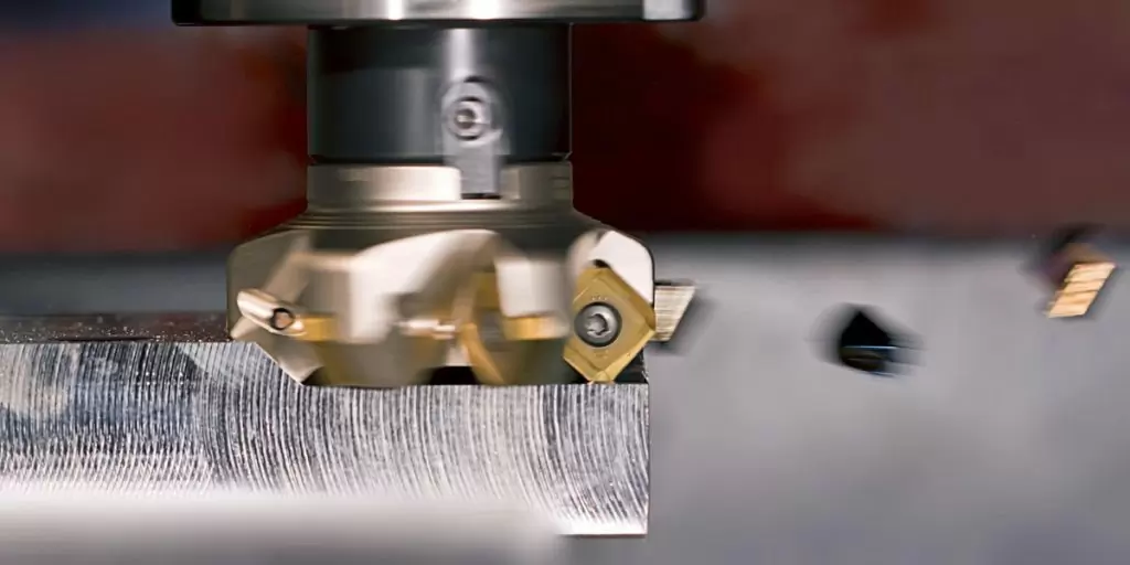
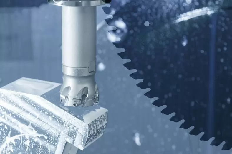
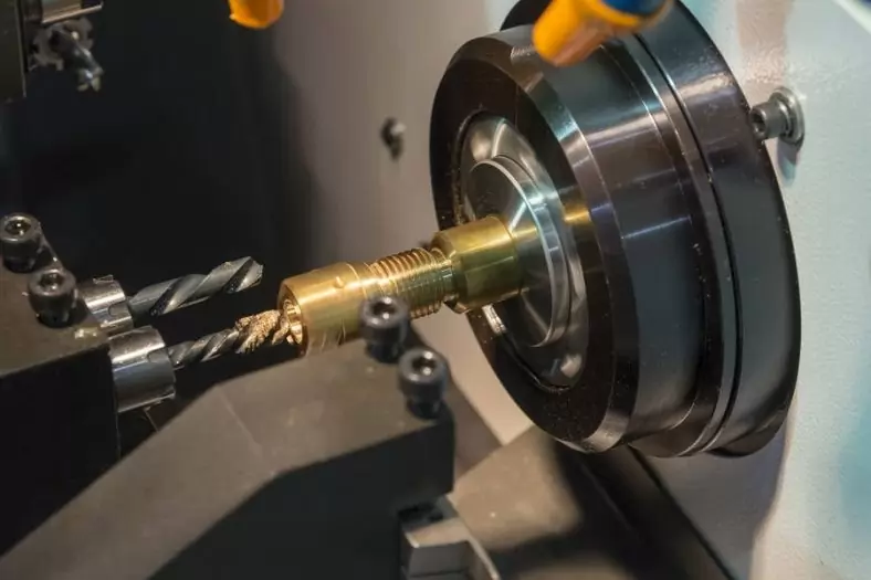
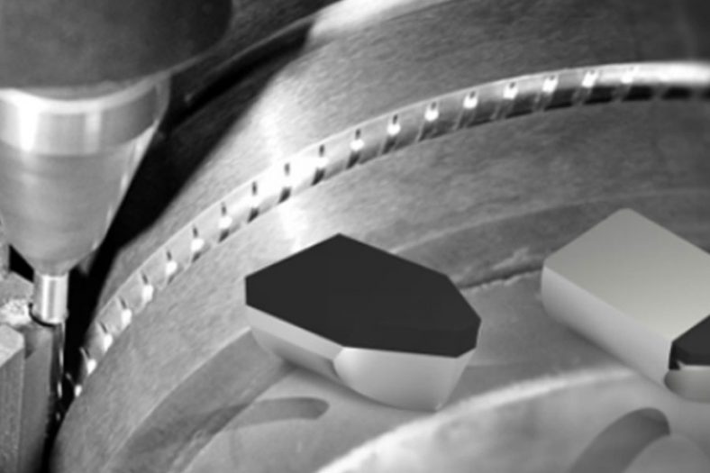
The Cutter Of Cnc Milling
There are many ways to classify milling cutters. One method is to divide milling cutters into two categories according to the tool clearance angle:
- Each tooth of the profile milling cutter grinds a small edge on the back of the cutting edge to form a relief angle. The cutting edge can be straight or curved.
- The cross section of each tooth of the forming or cam-shaped relief angle milling cutter is an eccentric curve on the back of the cutting edge to produce a relief angle. Each surface of the eccentric relief angle is parallel to the cutting edge and has the same shape of the cutting edge. This type of milling cutter can be sharpened only by grinding the rake face of the tooth.
As long as the shape of the cutting edge remains unchanged, another classification method of milling cutters is to classify them according to the method of installation of the milling cutter. The mandrel milling cutter has a center hole to allow the milling cutter to be mounted on the mandrel. The shank milling cutter has a taper shank or a straight shank. The milling cutter with the taper shank can be directly installed on the main shaft of the milling machine, while the milling cutter with the straight shank is clamped in the chuck. A face milling cutter is usually bolted to the end of the cutter shaft.
According to this classification method, general-purpose milling cutters can be classified as follows:
- Mandrel milling cutters: cylindrical milling cutters, angle milling cutters, side-edge milling cutters, cog milling cutters, staggered tooth milling cutters, forming milling cutters, slotting milling cutters, high-speed cutters.
- Shank milling cutters: face milling cutters, T-slot milling cutters, integral milling cutters, semicircular key seat milling cutters, sleeve milling cutters, high-speed cutters, hollow milling cutters. Tienai’s cylindrical milling cutter is a cylindrical or disc-shaped knife with straight or spiral teeth on the circumference. They can be used for milling planes. This is called flat fast making. Each tooth on a spiral milling cutter gradually contacts the workpiece. In a given time, there are usually many teeth made of iron, so that it can be made of iron. Less fretting, to get a smoother surface. Therefore, compared with straight-toothed iron knives, this type of force is usually used more.
- The teeth of the side edge milling cutter are similar to the cylindrical milling cutter except that they extend radially at one or both ends of the cylindrical cutter body. The teeth of side edge milling cutters can be straight or spiral. Such milling cutters are generally narrow and have a disc shape. In straddle milling, two or more side-edge milling cutters are often installed alternately on a shank at the same time and cut in parallel.
- The double groove milling cutter is composed of two side edge milling cutters, but when milling grooves, it is operated as a group milling cutter. Add some shims between the two milling cutters to adjust the distance between them.
- The staggered tooth milling cutter is a thin cylindrical milling cutter with interlaced cutter teeth, and adjacent cutter teeth have opposite helix angles. This kind of milling cutter is only used for peripheral milling after grinding, and there is a gap for chip discharge on the protruding side of each tooth. This type of milling cutter can be used for high-speed cutting and can play a unique role when milling deep grooves.
- The slotting cutter is a thin cylindrical cutter with a thickness of 1/32- 3/16 inches. The side of this milling cutter is disc-shaped with gaps to prevent adhesion. Compared with cylindrical milling cutters, this type of milling cutter has more teeth per inch of diameter. It is usually used for milling deep and narrow grooves and can be used for cutting.
The Accuracy Correction Of Cnc Milling
X-axis correction of milling machine
Slightly loosen the 4 bolts, but it is necessary to make sure that the 4 bolts still have some friction resistance. At this time, use the head to rotate the bolts to adjust the left and right angles. During the process, a dial indicator must be placed on the end of the spindle to measure the correct position of the worktable.
Y-axis correction of milling machine
Slightly loosen the 3 bolts, but make sure that the 3 bolts are not too loose to facilitate fine-tuning. At this time, use the arm to rotate the bolts and place a 100-point gauge on the end of the spindle to measure the correct position of the worktable.
Milling machine level correction
- Place the spirit level on the work surface.
- Check point A and B of the level, the allowable value is 0.06mm/m.
- If necessary, shims can be placed under the machine tool.
The Operating Procedures Of CNC Milling
- When milling irregular workpieces and using vises, indexing heads and special fixtures to hold the workpieces, the center of gravity of the irregular workpieces and the vise, indexing heads, special fixtures, etc. should be placed in the middle of the workbench as much as possible to avoid The workbench is not evenly stressed and deformed.
- During fast or automatic feed milling, do not move the worktable to the extremes to avoid squeezing the screw rod.
- Motorized tool setting is not allowed, and the tool setting should be done manually.
- When the workbench is reversing, the reversing handle must be stopped at the middle position first, and then reversing. Direct reversing is not allowed.
- When milling keyway shafts or cutting thin workpieces, prevent the indexing head or work surface from being damaged by milling.
- When milling a plane, a cutter head with more than four cutter heads must be used, and an appropriate cutting amount must be selected to prevent the machine tool from vibration during milling.
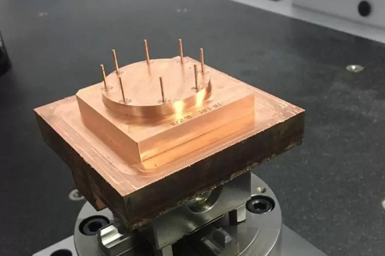
The Detail Of BE-CU Cnc Milling Company
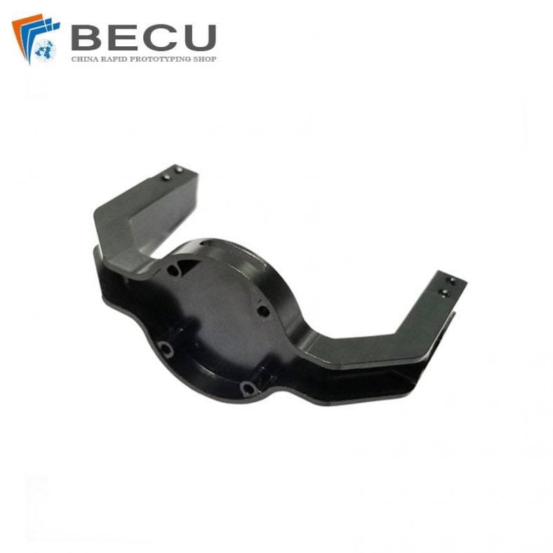
Looking for low cost CNC milling parts with unparalleled quality? BE-CU Prototype is a professional China CNC company provides superior precision CNC milling service with advanced machines including CMC milling center and milling machining centers from the general 3-axis to 5-axis and accomplished machinists. Our experienced operators proficient in CAD (computer-aided design) and CAM (computer-aided manufacturing) programs are always finding the best way to produce the highest quality CNC milled parts & components for clients. With strong capabilities and extensive experiences, we can provide top-grade but cost-effective custom CNC milling services from China including 3-axis CNC milling and 5-axis milling for high-speed CNC manufacturing, rapid prototyping, and precision CNC milling and turning. Our high-quality rapid CNC milling products are involved in the field of automation design, lockset, automobile parts machining, machinery milling, defense industry, medical equipment, lighting parts machining, etc.
-

AZ91D CNC Machining Quadcopter Arm Landing Gear
-
CNC Machining Lightweight Magnesium Alloy AZ91D Drone Gimbal Parts
-

CNC Machining Magnesium AZ61 Drone Blade Protection Cover
-

CNC Machining Magnesium AZ91D AI Ar Glasses Frame