According to the different structural spinning shapes, materials, and uses of the formed workpieces, the commonly used spinning methods include the following:
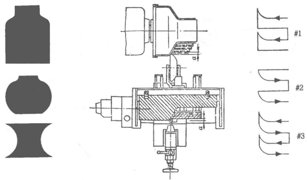
Inner Core Molding Spinning
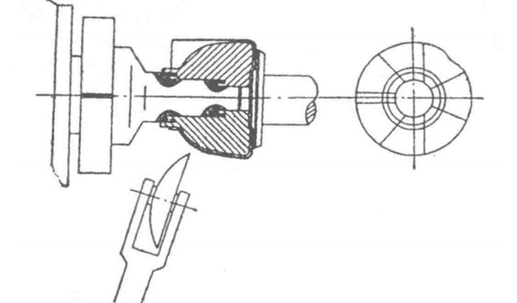
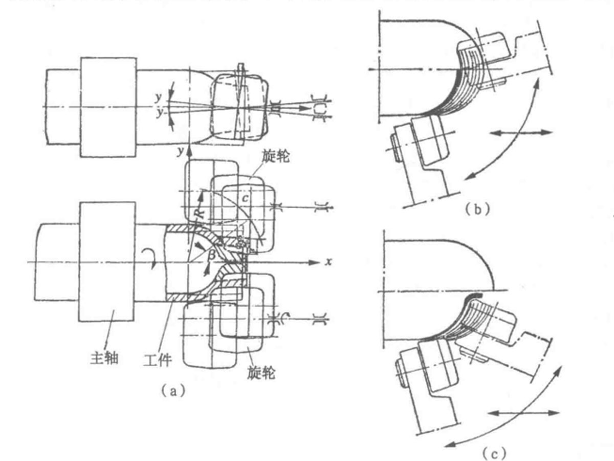
If the blank is a cylindrical part open at both ends and requires necking at its ends, the inner core method shown in Figure 2-27 can be used. First, the blank is placed on the cylindrical core mold section and secured using mechanical or hydraulic clamps. The section to be formed extends out and hangs freely. The spindle drives the blank to rotate, while the spinning wheel moves according to a profiling plate, programmable control, or numerical control program, performing spinning operations until the desired shape is achieved. The left image shows the shape of the rotating workpiece, while the right image illustrates three motion trajectories of the spinning wheel.
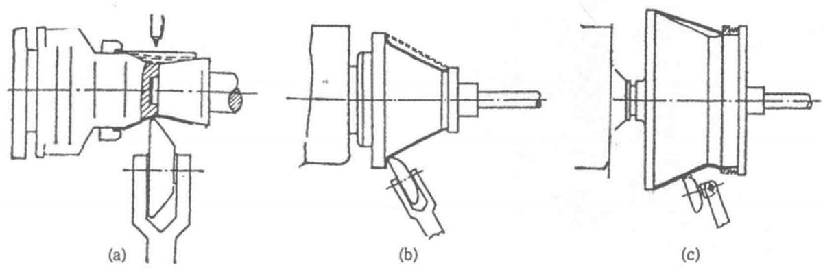
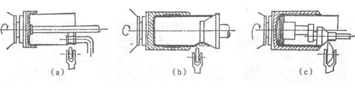
If the necking position is not at the end of the workpiece but in the middle, as shown in the three inner mold necking methods in Figure 2-28, Figure a depicts necking at the middle of a cylindrical part. To ensure that the workpiece can be removed from the core mold after forming, a combination core mold with a portion at the minimum diameter must be used, along with a centering shaft. The heavier part of the core mold is fixed on the machine spindle, while the lighter part is mounted on the tailstock.
After forming, the tailstock and the connected half of the core mold are withdrawn together, allowing for the workpiece to be removed.
The spinning process is the same as described above. Figure b shows a conical blank being necked at the larger end with a flange and a small arc at the smaller end, resembling the intake of a fan.
The blank is pressed against the large shoulder of the core mold with a tailstock. After spinning, the tailstock is retracted to unload the material. Figure c illustrates a conical blank secured at one end on the large shoulder of the core mold, with the other end free.
The core mold is also a combination type, similar to Figure a. Additionally, to facilitate necking, an elastic pressing ring is used. When the material has poor plasticity and a large deformation occurs, heated spinning can be employed.
Segmented Combination Core Molding Spinning
When necking the mouth of kettle-shaped workpieces, the segmented combination core mold shown in Figure 2-29 can be used. As seen in the figure, the core mold, consisting of several modules, is installed on the spindle flange of the machine. During design, consideration should be given to the ease of removing these modules from the top after spinning, and they should be quickly reassembled for reuse. This combination core mold can handle about 60% of the workpieces, with a maximum end diameter of 250 mm; otherwise, due to the heavy weight of the core mold, processing and installation can become inconvenient.
Hollow Support Tubes or Trays or Rods Spinning.
When the neck size of the workpiece to be spun is very small and the necking amount is large, if the above methods cannot be used, hollow support tubes, trays, or clamping rods, as shown in Figure 2-30, need to be employed. The hollow support tube or tray with a bottom is concentrically installed on the machine spindle. The tubular blank is first placed in the support tube and then pressed against the bottom of the hollow support tube using a clamping rod mounted on the tailstock (not shown in the figure).
The working section diameter of the clamping rod is equal to the neck diameter of the spun workpiece. The necking process is similar to that shown in Figure 2-26; the difference is that the necking of the larger diameter section is done using the core-less method, and after spinning, the clamping rod is withdrawn to take out the workpiece. Figures c and d show workpieces being clamped with jaws on the spindle, with a short tailstock rod at the necking section.
Roller Molding Spinning
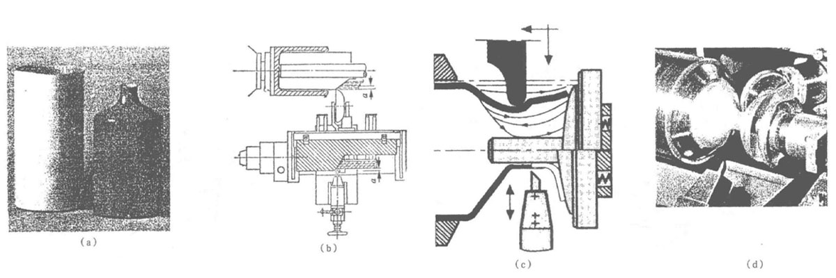
Due to the large size of the workpiece, using the above combination core molds can lead to excessive weight. When necking occurs at the end of the workpiece with a moderate deformation amount, a roller can replace the core mold (referred to as roller molding), as shown in Figure 2-31. When the ratio of the necking diameter to the initial diameter of the blank is not less than 50%, the eccentric inner roller mold shown in Figure c can be used. Additionally, an independent component can be mounted on the tailstock.
The pressure block, connecting rod, and rolling bearings of the roller mold are pushed by the tailstock hydraulic cylinder, ensuring that the profile of the roller matches the shape of the neck of the workpiece. After placing the blank in the support tube, the tailstock hydraulic cylinder pushes the roller mold to press against the bottom of the blank. The pressure block, blank, and support tube rotate concentrically with the spindle, while the roller mold rotates around its own axis due to contact friction with the workpiece.
This allows for necking as previously described. When designing this set of tools, it is also essential to ensure that the workpiece can be removed from the eccentric roller mold after spinning, meaning that the inner diameter of the neck of the workpiece should be slightly larger than the radius of the roller plus the centering gap. It should also have a slight clearance, as the same set of tools can process necks with the same shape but different diameters by merely adjusting the eccentric distance, thus reducing processing costs. Figure 2-31 (a) illustrates the use of roller molds for small-sized workpieces, while Figure b shows the roller mold installed coaxially with the spindle and workpiece for larger diameter necking.
Core-less Spinning
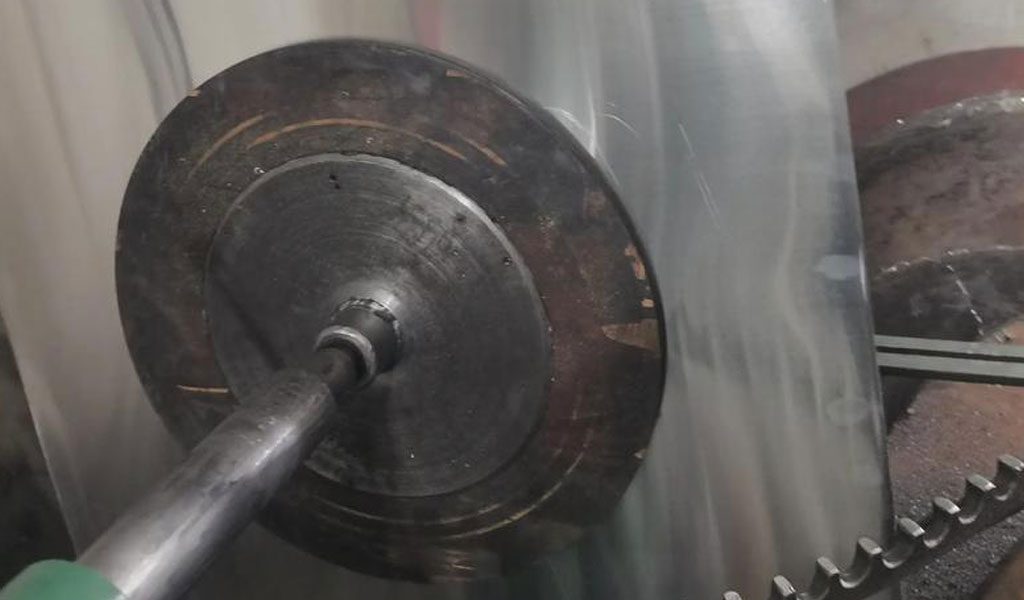
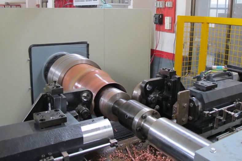
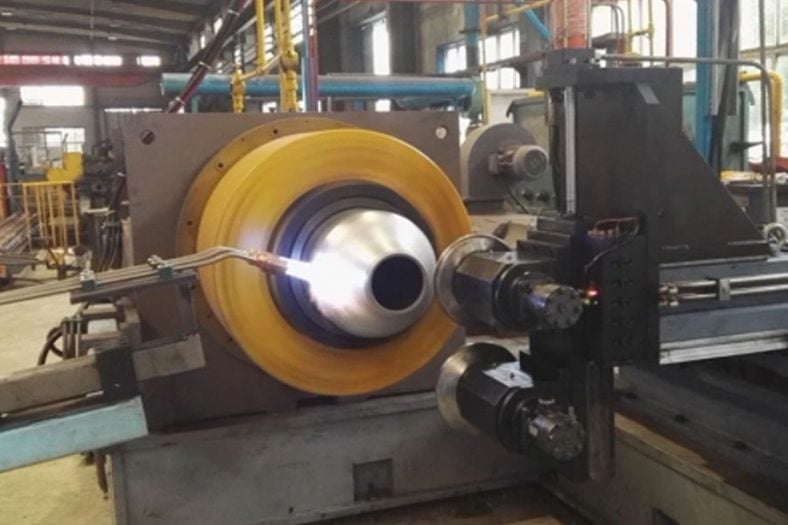
If necking occurs at the end of the workpiece, forming a closed bottom or a very small opening where no core can be used, the core-less method (or air mold) can be employed, as illustrated in Figure 2-32 for the forming of a bottle cap and closure. The process involves placing a heated tube blank from a furnace into the hollow spindle and chuck of the spinning machine, with the section to be formed extending out and hanging freely, secured by the chuck.
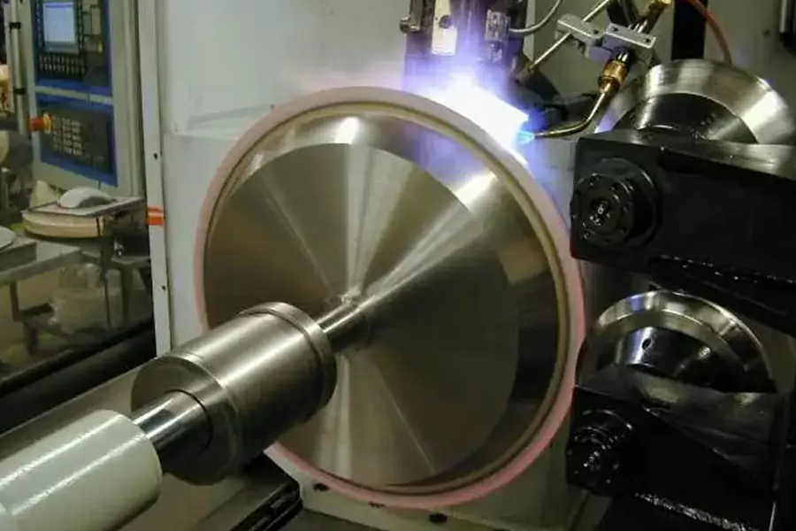
Once the spindle drives the workpiece to rotate, a flame gun is used to apply supplementary heating to the blank until it reaches forging temperature. Subsequently, the spinning wheel on the rotating wheel frame performs a slightly larger arc swing of about 1/4 revolution to form the shape.
Following the usual procedure, the first pass of the spinning wheel starts from the opening, followed by reciprocating multiple passes of forward and reverse swings with radial feed spinning. Due to continuous step spinning, the diameter at the end of the blank decreases, resulting in a closed and fused bottom.
For the closure of the bottle neck, when the neck diameter is reached, the spinning wheel must move parallel to the workpiece axis to elongate and smooth the opening; the motion trajectory of the spinning wheel differs from that of the bottom closing. During the closing, the spinning wheel does not stop at the neck but rather crosses the workpiece axis (Figure b). To accelerate the spinning process, two symmetrically arranged spinning wheels, as shown in Figure 2-34a, can be used; one spinning wheel performs forward spinning while the other performs reverse spinning, alternating between the two. The profile of the spinning wheel is convex.
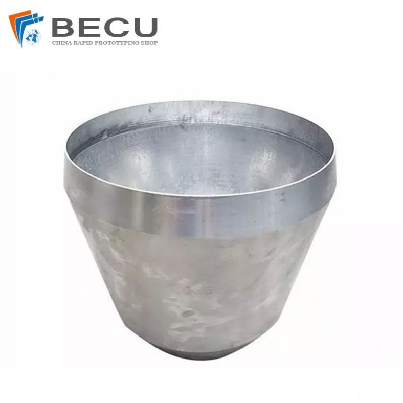
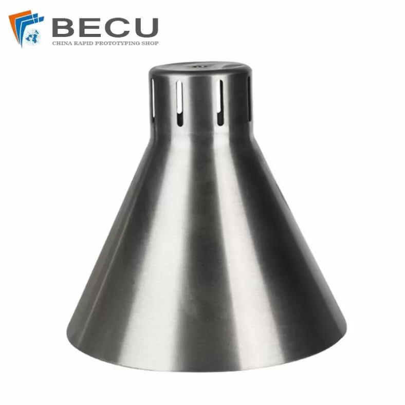
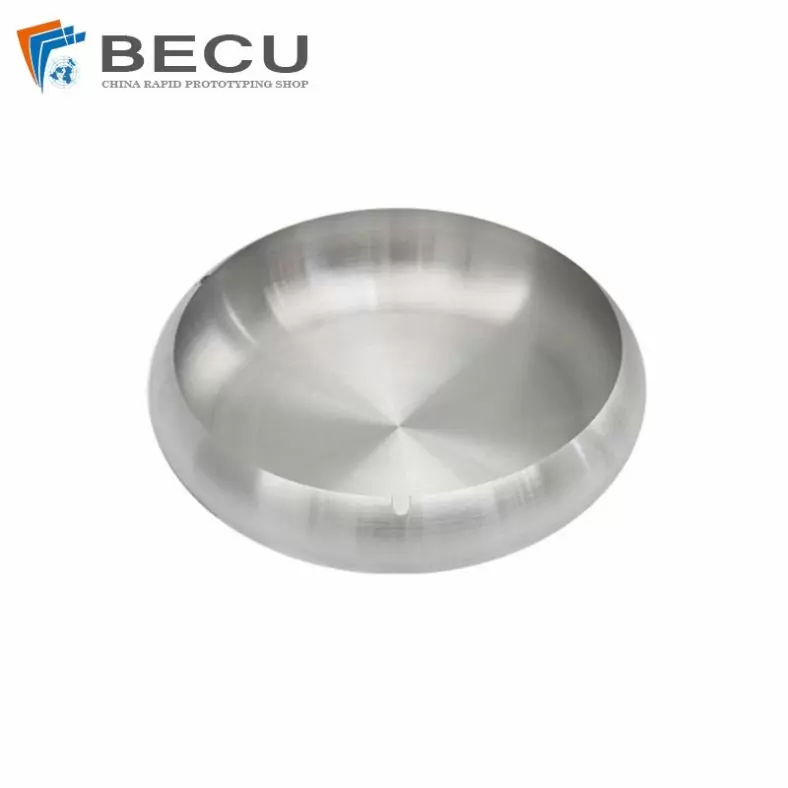
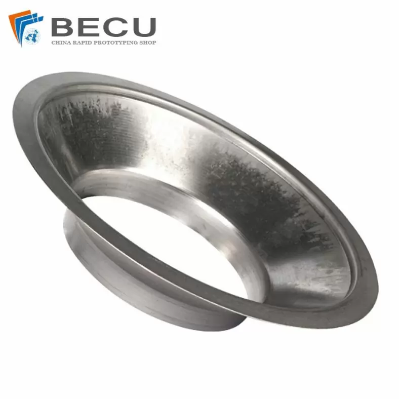
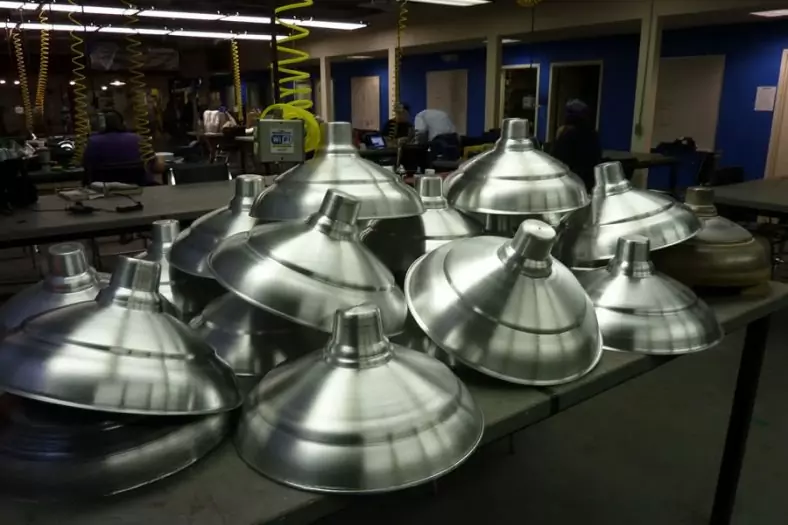
The Shapes Achieved Of Metal Spinning Parts
Simple shapes are easy to make in less time. But for complex shapes, it requires more time because it increases steps as per the block shape.
In addition to metal spinning, Be-cu.com also offers in-house tooling, welding, abrasive polishing and hydroforming, helping to drive down your costs and streamline production. Quicker turnaround times and lower costs are two of the most attractive advantages of metal spinning. The ability to form very thick components and large diameters with uniformity and high quality at low and high quantities, are more appealing reasons to consider metal spinning.To find out if metal spinning would be beneficial for your application or end product, contact us today.
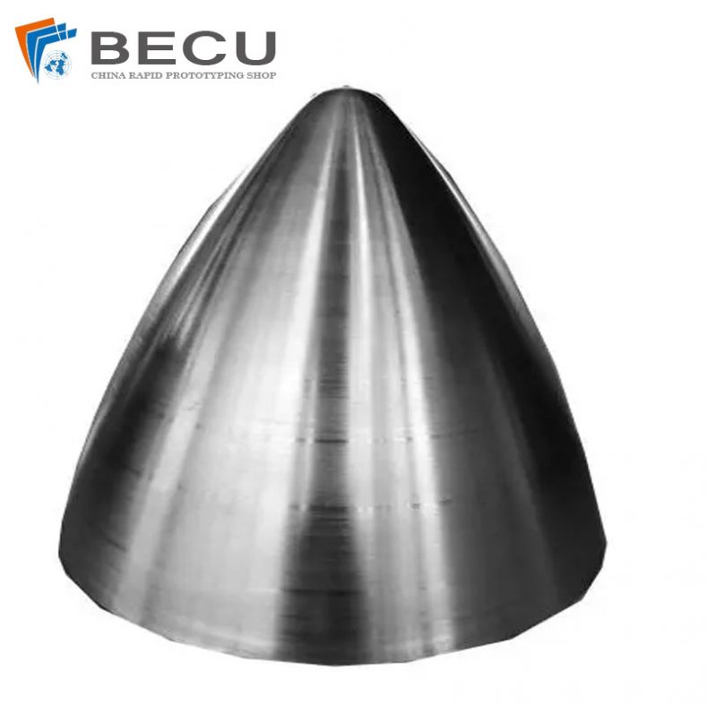
- Domed
- Flanged
- Domed with flange
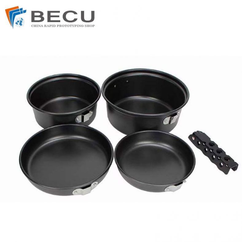
- Dished
- Semi elliptical
- Hemisphere
- Flanged, dished and flued
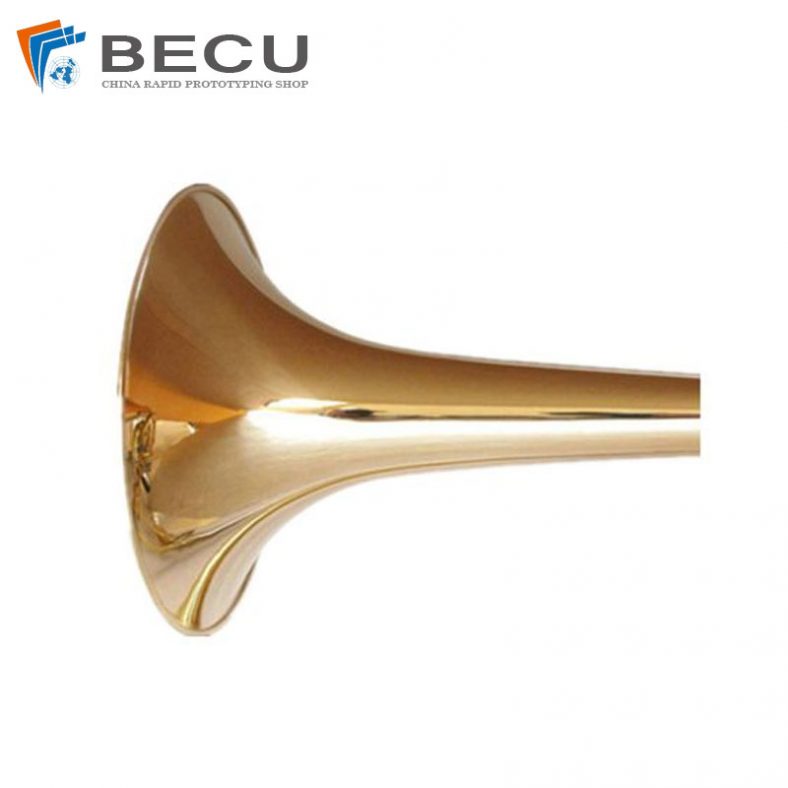
- Trumpet
The Detail Of BE-CU Metal Spinning Company
At Be-cu.com, we use a variety of materials for metal spinning such as cold rolled steel, hot rolled steel, aluminum spinning, stainless steel spinning, brass, copper spinning and exotic metals such as titanium and inconel. Be-cu Metal Spinning Section specializes in the forming of stainless steel. With our automated metal spinning lathes and the capabilities of our deep drawing, stamping and welding equipment, our ability to form your part to your specifications and within your budget are realistic. Be-cu Metal Spun Company has over 30 years of metal forming experience and has used the large metal spinning technology for a variety of industries such as aerospace, automotive, military, ordnance, plastics, lighting, pharmaceuticals, dairy, etc…
We have engineers on staff with metal spinning expertise to help guide you on designing a custom part and choose the optimal process to produce high quality spun parts at a competitive and affordable price. Tooling is custom made to form parts to your configuration.