
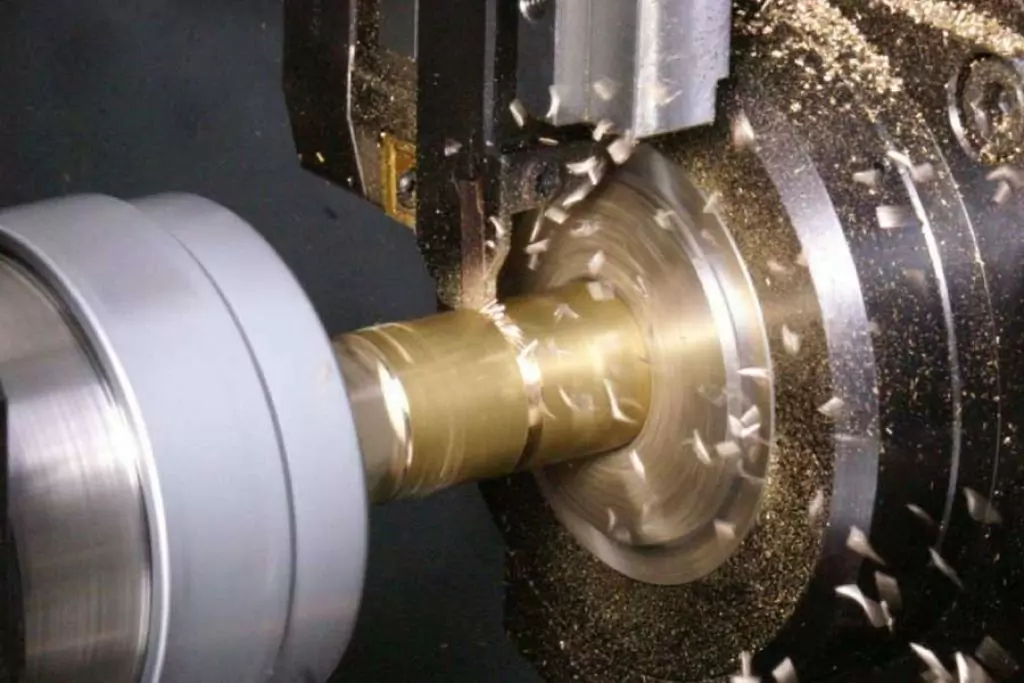
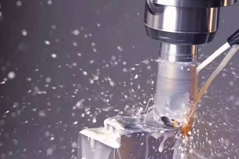
Cnc Turning is a cutting process in which the workpiece rotates and the turning tool moves in a straight line or a curve in a plane.
Cnc Turning Definition
Cnc Turning is generally carried out on a lathe to process the inner and outer cylindrical surfaces, end surfaces, conical surfaces, forming surfaces and threads of the workpiece.Drills, reamers, reamers, taps, dies and knurling tools can also be used on the lathe for corresponding processing.Cnc Lathes are mainly used for machining shafts, discs, sleeves and other rotating or non-rotating workpieces with rotating surfaces. It is the most widely used type of machine tool processing in machinery manufacturing and repair factories.
What Is NC Turning
NC turning strives to use large cutting depth and large feed to improve turning efficiency without reducing the cutting speed, but the machining accuracy can only reach IT11, and the surface roughness is Rα20-10μm. Semi-finishing turning and finishing turning try to use high-speed and small feed and cutting depth, the machining accuracy can reach IT10-IT7, and the surface roughness is Rα10-0.16μm.
The high-speed precision turning of non-ferrous metal parts with the finely-refined diamond turning tool on the high-precision lathe can make the machining accuracy reach IT7-IT5, and the surface roughness is Rα0.04-0.01μm. This kind of turning is called “mirror turning”.

The Detail Of BE-CU Cnc Turning Company
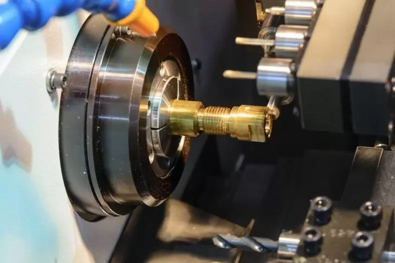
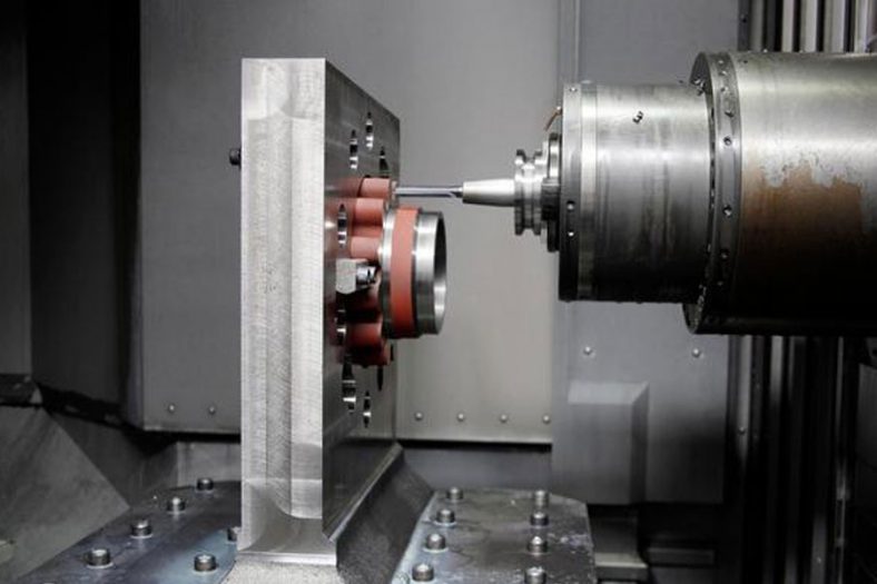
Be-cu.com is an experienced precision CNC turning services supplier, manufacturer, exporter in China, has been specialized in offering best OEM CNC lathe services for superior quality low cost CNC turning parts, CNC lathe parts or high precision machined components with the operation of an impressive range of state-of-the-art turning machines, such as washers, bolts, shafts, rivets, spacers, sleeves, nipples, stainless steel fittings, pipe fittings, light fittings, wheel studs, etc. Our advanced CNC turning center routinely works with a wide variety of materials, ranging from copper, brass, stainless steel, carbon steel, aluminum, and titanium. We can always choose a suitable precision turning process to reach your requirements. Our custom cnc machining services ensure that our customers receive the highest quality CNC turned parts.
-
Restoration of Petroleum Splined Shafts through Supersonic Thermal Spray Coating
-

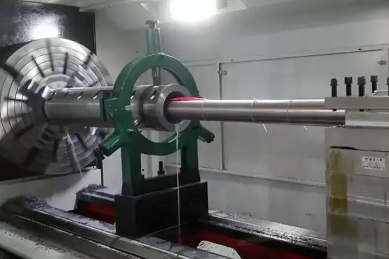
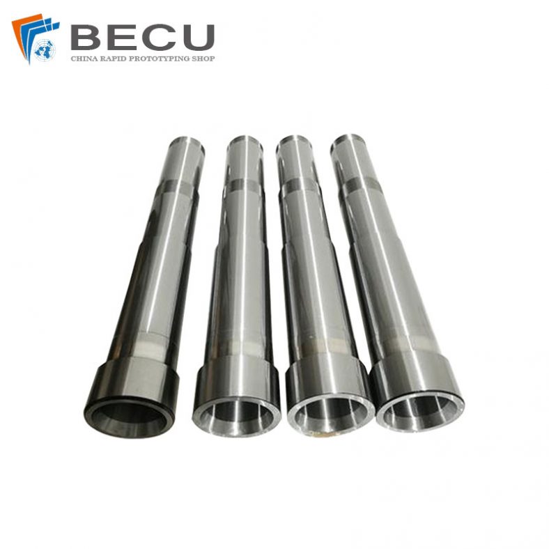
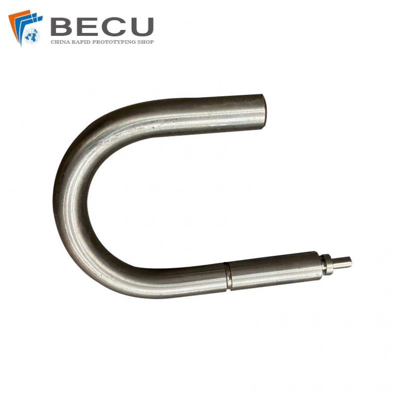
Large CNC Turning Inconel 625 Automobile Engine Camshafts
-
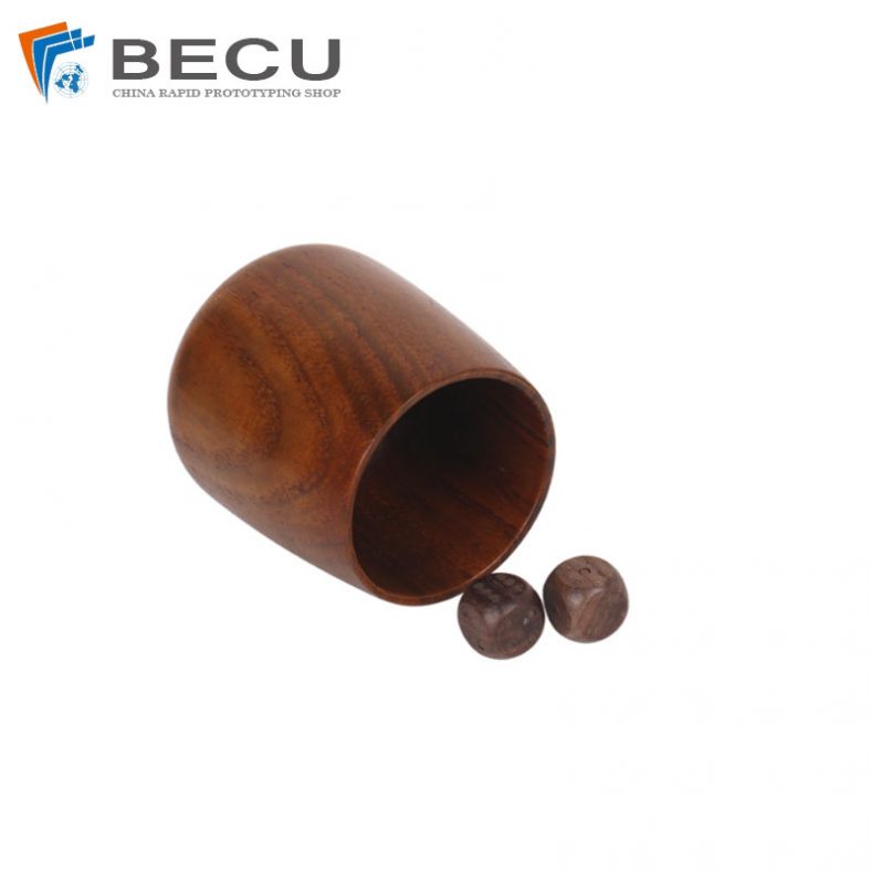
Precision Turning Solid Wood Dice
-

Custom Wood Chess Board, Sets And Pieces
-
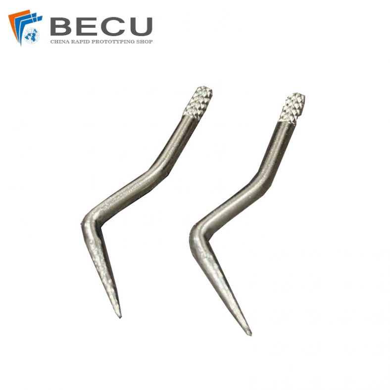
Swiss Machining And Bending 304 Hand Sewing Needle For Textile Machinery
-
Automatic Swiss Turning Stainless Steel 316L U-bolt
-

4 Axis CNC Machining Titanium Grade 5 Mobile Phone Buttons
-
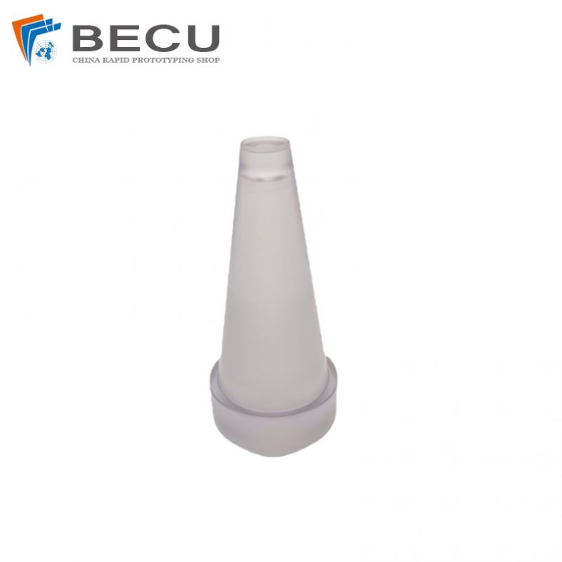
Precision Turning 20° Acrylic Downlight Reflector
The Working Principle Of Cnc Turning
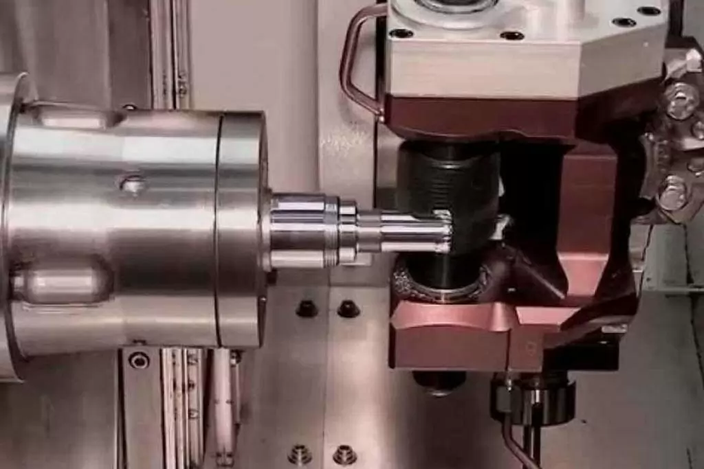
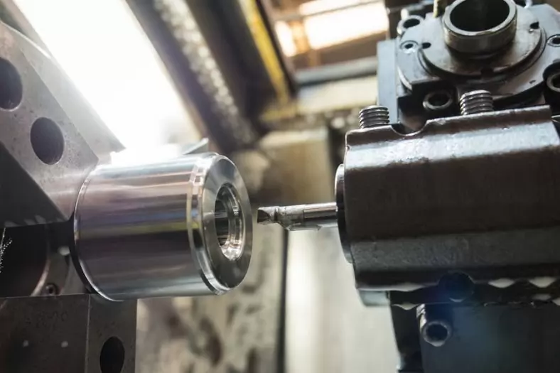
When turning the inner and outer cylindrical surfaces, the turning tool moves in a direction parallel to the axis of rotation of the workpiece. When turning the end face or cutting the workpiece, the turning tool moves horizontally in the direction perpendicular to the axis of rotation of the workpiece. If the trajectory of the turning tool is at an oblique angle to the axis of rotation of the workpiece, a conical surface can be machined. The surface of the turning body formed by turning can adopt the forming tool method or the tool tip trajectory method. When turning, the workpiece is driven by the main shaft of the machine tool to rotate for the main movement; the turning tool clamped on the tool holder is for the feed movement. Cutting speed v is the linear speed (m/min) at the point of contact between the machined surface of the rotating workpiece and the turning tool; the depth of cut is the vertical distance (mm) between the machined surface and the machined surface of the workpiece during each cutting stroke. When cutting and forming turning, it is the contact length (mm) between the turning tool and the workpiece perpendicular to the feed direction. The feed represents the displacement (mm/revolution) of the turning tool in the feed direction per revolution of the workpiece, and it can also be expressed as the feed per minute (mm/min) of the turning tool. When turning ordinary steel with a high-speed steel turning tool, the cutting speed is generally 25-60 m/min, and the hard alloy turning tool can reach 80-200 m/min; the maximum cutting speed can reach 300 when the coated carbide turning tool is used. M/min or more.
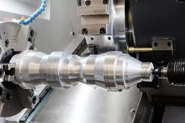
Turning is generally divided into two types: rough turning and finishing turning (including semi-finishing turning). Rough turning strives to use large cutting depth and large feed rate to improve turning efficiency without reducing the cutting speed, but the machining accuracy can only reach IT11, and the surface roughness is Rα20-10 microns; semi-finished turning and finishing turning Try to use high-speed and small feed and cutting depth, the machining accuracy can reach IT10~7, and the surface roughness is Rα10~0.16 microns. High-speed precision turning of non-ferrous metal parts with finely developed diamond turning tools on high-precision lathes can make the machining accuracy reach IT7~5, and the surface roughness is Rα0.04~0.01 microns. This kind of turning is called “mirror turning”. If the concave and convex shapes of 0.1 to 0.2 micrometers are drilled on the cutting edge of the diamond turning tool, the surface of the turning will produce extremely small and neatly arranged stripes, which will show a brocade-like luster under the effect of light diffraction. As a decorative surface, this kind of turning is called “Rainbow Turning”.
During turning processing, if the turning tool rotates in the same direction with the workpiece at the corresponding speed ratio (the tool speed is generally several times the workpiece speed) while the workpiece is rotating, the relative motion trajectory of the turning tool and the workpiece can be changed to produce Workpieces with polygonal cross-sections (triangular, square, prismatic, hexagonal, etc.). If the tool holder is given a periodic radial reciprocating motion for each revolution of the workpiece while the turning tool is longitudinally feeding, then the surface of cams or other non-circular cross-sections can be machined. On a shovel lathe, the flank face of certain multi-tooth tools (such as forming milling cutters, gear hobs) can be machined according to a similar working principle, which is called “shovel back”.
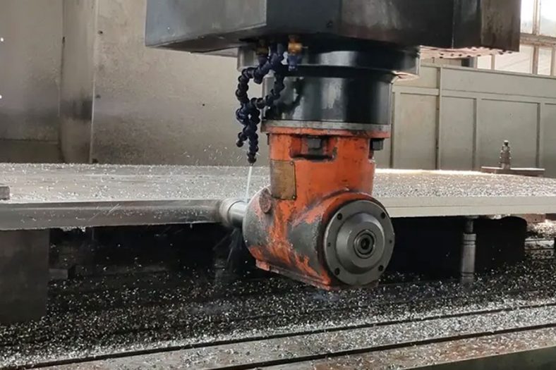
Among all kinds of metal cutting machine tools, lathes are the most widely used, accounting for about 50% of the total number of machine tools. The lathe can not only use turning tools to turn the workpiece, but also use drills, reamers, taps and knurling tools for drilling, reaming, tapping and knurling operations. According to different process characteristics, layout forms and structural characteristics, lathes can be divided into horizontal lathes, floor lathes, vertical lathes, turret lathes and profile lathes, among which most are horizontal lathes.
The Material Options Of Cnc Machining

The Process Characteristics Of Cnc Turning
1.It is easy to ensure the position accuracy of each processing surface of the workpiece
- a For example, it is easy to ensure the coaxiality requirements; use the chuck to install the workpiece, the rotation axis is the rotation axis of the lathe spindle; use the front and rear centers to install the workpiece, the rotation axis is the center connection between the two centers
- b It is easy to ensure the perpendicularity of the end face and the axis. The verticality of the horizontal slide guide rail and the axis of rotation of the workpiece is required.
2.The cutting process is relatively stable, avoiding inertial force and impact force
Allows the use of larger cutting parameters, high-speed cutting, which is conducive to productivity improvement.
3.Suitable for finishing of non-ferrous metal parts
When the surface roughness of non-ferrous metal parts is large and the Ra value is small, grinding is not suitable, and turning or milling is required. High quality can be achieved when using diamond turning tools for fine turning.
4.The tool is simple;
It is convenient to manufacture, sharpen and install turning tools.
The Development History Of Cnc Lathes
The ancient lathe used hands or pedals to rotate the work piece through a rope and hold the tool for cutting.
- In 1797, British mechanical inventor Mozley created a modern lathe that uses a screw to drive the tool post, and in 1800 it adopted an exchange gear to change the feed speed and the pitch of the thread to be processed.
- In 1817, another Englishman, Roberts, used a four-stage pulley and back-wheel mechanism to change the spindle speed.
- In order to improve the degree of mechanization and automation, in 1845, Fitch in the United States invented the turret lathe.
- In 1848, the back wheel lathe appeared again in the United States.
- In 1873, Spencer of the United States made a single-spindle automatic lathe, and soon he made a three-spindle automatic lathe.
- At the beginning of the 20th century, a lathe with a gearbox driven by a separate electric motor appeared.
- After the First World War, various high-efficiency automatic lathes and specialized lathes developed rapidly due to the needs of the munitions, automobiles and other machinery industries.
- In order to improve the productivity of small batches of workpieces, lathes with hydraulic profiling devices were promoted in the late 1940s. At the same time, multi-tool lathes were also developed.
- In the 1950s, program-controlled lathes with punched cards, latch plates and dials were developed. Numerical control technology began to be used in lathes in the 1960s and developed rapidly after the 1970s.
The Methods Of Cnc Turning
- Rough turning and turning is the most economical and effective method for external roughing. Since the main purpose of roughing is to quickly remove excess metal from the blank, improving productivity is its main task. Rough turning usually uses the largest possible backfeed and feed to improve productivity. In order to ensure the necessary tool life, the cutting speed is usually low. When rough turning, the turning tool should choose a larger entering angle to reduce the back force and prevent the bending deformation and vibration of the workpiece; choose a smaller rake angle, clearance angle and negative edge inclination to enhance the turning tool The strength of the cut part. The machining accuracy that can be achieved by rough turning is IT12~IT11, and the surface roughness Ra is 50~12.5μm.
- The main task of fine turning is to ensure the required machining accuracy and surface quality of the parts. The outer surface of the finish turning is generally processed with a smaller back-cutting amount and feed rate and a higher cutting speed. When processing the outer circle of large shaft parts, the wide-blade turning tool is often used for low-speed precision turning. When finishing turning, the turning tool should choose a larger rake angle, a rear angle and a positive tool inclination to improve the quality of the processed surface. Fine turning can be used as the final machining of a higher precision outer circle or as a pre-machining for fine machining. The machining accuracy of fine turning can reach IT8~IT6, and the surface roughness Ra can reach 1.6~0.8μm.
- The characteristics of the fine car are: the back-cutting amount and the feed rate are extremely small, and the cutting speed is as high as 150-2000m/min. Fine cars generally use cubic boron ammonia (CBN), diamond and other superhard material tools for processing. The machine tool used must also be a high-precision or precision machine tool with high-speed rotation of the spindle and high rigidity. The machining accuracy and surface roughness of the fine car are roughly equivalent to those of ordinary cylindrical grinding, the machining accuracy can reach IT6 or more, and the surface roughness Ra can reach 0.4 to 0.005 μm. It is mostly used for precision machining of non-ferrous metal workpieces with poor grinding workability. Fine turning is more effective for aluminum and aluminum alloy workpieces that are likely to block the pores of the grinding wheel. When processing large precision external surfaces, fine turning can replace grinding.
The Technical Problem Of Cnc Turning
Turning is one of the most widely used in the machine manufacturing industry. There are a large number of lathes, a large number of personnel, a wide range of processing, and many tools and fixtures are used. Therefore, the safety technology of turning is particularly important. , Its key tasks are as follows:
- Damage from cutting chips and protective measures. The toughness of various steel parts processed on the lathe is better, the chips produced during turning are full of plastic curl, and the edges are relatively sharp. During high-speed cutting of steel parts, red hot and long chips are formed, which are very easy to hurt people. At the same time, they are often wound on the workpiece, turning tools and tool holders. Therefore, iron hooks should be used to clean up or break them in time during work. It should be stopped to remove it when it is time, but it is never allowed to remove or pull off by hand. In order to prevent chip damage, chip breaking, chip flow control measures and various protective baffles are often taken. The chip breaking measure is to grind chip breakers or steps on the turning tool; use a suitable chip breaker and mechanically clamp the tool.
- The clamping of the workpiece. In the process of turning, there are many accidents that damage the machine tool, break or break the tool, and cause the workpiece to fall or fly out due to improper clamping of the workpiece. Therefore, in order to ensure the safe production of turning processing, special attention must be paid when loading the workpiece. For parts of different sizes and shapes, you should choose appropriate fixtures, regardless of whether the three-jaw, four-jaw chuck or the connection between the special fixture and the spindle must be stable and reliable. The workpiece must be clamped and clamped. The sleeve can be used to clamp the large work piece to ensure that the work piece does not shift, fall off, or throw out when the workpiece is rotated at high speed and cut. If necessary, use the center frame, center frame, etc. to enhance the clamping. Remove the handle immediately after the card is tightened.
- Safe operation. Before working, check the machine tool thoroughly and confirm that it is good before use. The clamping of the workpiece and the tool ensures the correct position, firmness and reliability. During the machining process, the machine must stop when changing tools, loading and unloading workpieces, and measuring workpieces. Do not touch the workpiece or wipe it with cotton silk when rotating. It is necessary to select the cutting speed, feed rate and strenuous depth appropriately, and no overload processing is allowed. Workpieces, fixtures and other sundries are not allowed to be placed on the head of the bed, the knife rest and the surface of the bed. When using a file, move the turning tool to a safe position, with the right hand in front and the left hand in the back to prevent the sleeves from being caught. The machine tool must have a dedicated person responsible for use and maintenance, and other personnel must not use it.
The Precautions Of Cnc Turning
The machining technology of CNC lathes is similar to that of ordinary lathes, but because CNC lathes are one-time clamping and continuous and automatic machining to complete all turning processes, the following aspects should be paid attention to.
1. Reasonable choice of cutting amount
For high-efficiency metal cutting machining, the processed material, cutting tools, and cutting conditions are the three major elements. These determine the machining time, tool life and machining quality. The economical and effective machining method must be a reasonable choice of cutting conditions. The three elements of cutting conditions: cutting speed, feed and depth of cut directly cause tool damage. With the increase in cutting speed, the temperature of the tool tip will rise, which will cause mechanical, chemical, and thermal wear.
Cutting speed increased by 20%, tool life will be reduced by 1/2. The relationship between the feed condition and the wear on the back of the tool occurs in a very small range. But the feed rate is large, the cutting temperature rises, and the back wear is large. It has less influence on the tool than cutting speed. Although the effect of cutting depth on the tool is not as large as the cutting speed and feed rate, when cutting at a small depth of cut, the material to be cut will produce a hardened layer, which will also affect the life of the tool.
The user should choose the cutting speed to be used according to the processed material, hardness, cutting state, material type, feed amount, depth of cut, etc. The selection of the most suitable machining conditions is based on these factors. Regular, stable wear and longevity are the ideal conditions. However, in actual operations, the choice of tool life is related to tool wear, dimensional changes to be processed, surface quality, cutting noise, and machining heat. When determining the machining conditions, it is necessary to conduct research according to the actual situation. For difficult-to-process materials such as stainless steel and heat-resistant alloys, coolants or blades with good rigidity can be used.
2. Choose a tool reasonably
- When roughing, choose high-strength and durable tools to meet the requirements of large back-grabbing and large feed when roughing.
- When finishing turning, choose high-precision and durable tools to ensure the requirements of machining accuracy.
- In order to reduce the time of tool change and facilitate tool setting, machine-clamped knives and machine-clamped blades should be used as much as possible.
3. Reasonable selection of fixtures
- Try to use general fixtures to clamp the workpiece, avoid using special fixtures;
- The positioning datums of the parts overlap to reduce positioning errors.
4. Determine the machining route
The machining route is the movement track and direction of the tool relative to the part during the machining of the index-controlled machine tool.
- It should be able to ensure the machining accuracy and surface roughness requirements;
- The machining route should be shortened as much as possible to reduce the idle travel time of the tool.
5. The relationship between machining route and machining allowance
Under the condition that the CNC lathe has not yet reached the popular use, the excess margin on the blank, especially the margin containing the forging and casting hard skin layer, should be arranged on the ordinary lathe for machining. If you must use a CNC lathe for machining, you need to pay attention to the flexible arrangement of the program.
6. Main points of fixture installation
The connection between the hydraulic chuck and the hydraulic clamping cylinder is realized by a pull rod. The main points of hydraulic chuck clamping are as follows: First, use a moving hand to remove the nut on the hydraulic cylinder, remove the pull tube, and pull it out from the back of the spindle, and then use it. Remove the fixing screw of the chuck by moving your hand to remove the chuck.
The General Rules Of Cnc Turning
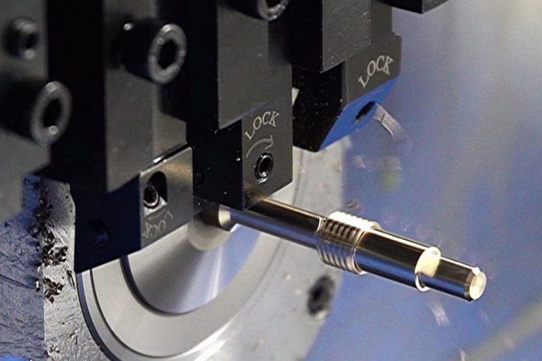
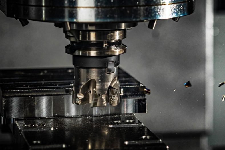
1.Clamping Of Turning Tools
- The tool bar of the turning tool should not extend too long from the tool holder, and the general length should not exceed 1.5 times the height of the tool bar (except for turning holes, grooves, etc.)
- The center line of the tool bar of the turning tool should be perpendicular or parallel to the cutting direction.
- Adjustment of the height of the tool tip:When turning the end face, turning cone surface, turning thread, turning forming surface and cutting solid workpieces, the tool tip should generally be the same height as the axis of the workpiece ; The outer circle of the rough turning, the finishing hole, and the tool tip should generally be slightly higher than the axis of the workpiece ; When turning slender shafts, rough turning holes, or cutting hollow workpieces, the tool tip should generally be slightly lower than the workpiece axis.
- The bisector of the tip angle of the thread turning tool should be perpendicular to the axis of the workpiece.
- When clamping the turning tool, the shims under the tool bar should be small and flat, and the screws for pressing the turning tool should be tightened.
Workpiece Clamping
- When using a three-jaw self-centering chuck to clamp a workpiece for rough turning or finishing turning, if the diameter of the workpiece is less than 30 mm, its overhang length should not be greater than 5 times the diameter, and if the diameter of the workpiece is greater than 30 mm, its overhang The length should not be greater than 3 times the diameter.
- When using four-jaw single-action chucks, faceplates, angle irons (bent plates), etc. to clamp irregular and heavy workpieces, a counterweight must be added.
- When machining shaft workpieces between centers, adjust the center axis of the tailstock to coincide with the axis of the lathe spindle before turning.
- When machining a slender shaft between two centers, a follower or a center frame should be used. Pay attention to adjusting the top tightening force during the processing, and the dead center and the center frame should be lubricated.
- When using the tailstock, extend the sleeve as short as possible to reduce vibration.
- When clamping a workpiece with a small supporting surface and a high height on a vertical car, a raised jaw should be used, and a tie rod or a pressure plate should be added to the appropriate position to compress the workpiece.
- When turning cast and forging parts of wheels and sleeves, they should be aligned according to the unprocessed surface to ensure that the wall thickness of the workpiece is uniform after processing.
Cnc Lathing Rules
- When turning a stepped shaft, in order to ensure the rigidity during turning, generally the part with the larger diameter should be turned first, and the part with the smaller diameter should be turned afterwards.
- When grooving the workpiece on the shaft, it should be done before finishing to prevent deformation of the workpiece.
- When finishing a threaded shaft, generally the unthreaded part should be finished after threading.
- Before drilling, the end face of the workpiece should be flattened. If necessary, punch the center hole first.
- When drilling deep holes, generally drill pilot holes first.
- When turning (Φ10—Φ20) ㎜ holes, the diameter of the tool holder should be 0.6-0.7 times the machined hole diameter; when machining holes with a diameter larger than Φ20 mm, the tool holder with the tool head should generally be used.
- When turning multiple threads or multiple worms, try cutting after adjusting the gears.
- When using an automatic lathe, adjust the relative position of the tool and the workpiece according to the machine tool adjustment card. After the adjustment is done, test turning is required. The first piece can be processed only after the first piece is qualified. Pay attention to the wear of the tool and the size and surface roughness of the workpiece at any time during the processing. Spend.
- When turning on a vertical lathe, after the tool post is adjusted, the beam cannot be moved at will.
- When the relevant surface of the workpiece has position tolerance requirements, try to complete the turning in one clamping.
- When turning the cylindrical gear blank, the hole and the reference end face must be processed in one clamping. If necessary, a marking line should be drawn near the gear index circle on the end face.