
By establishing the digital model of the high-speed precision press, the motion simulation of the crank-slider mechanism and the balance-slider type dynamic balancing device is carried out. On the basis of kinematics analysis, the relationship between the weight change of the dynamic balance slider and the periodic change of the unbalanced inertial force of the press, the relationship between the slider movement speed change and the change of the unbalanced inertial force, and the effect of the balance cylinder are studied.

With the intuitive and convenient modern design method, the design method of the balance system of the high-speed precision press is explored. High-speed precision press is an automatic, precise and efficient forging equipment, ideal equipment for mass production of precision and complex parts in electrical machinery, electrical appliances, electronics, instruments, hardware and other industries. Under normal circumstances, the working efficiency of high-speed precision presses is more than ten times that of ordinary presses. The processed parts have stable quality and good consistency, and can significantly reduce the occurrence of safety accidents, which is very beneficial to improving the comprehensive competitiveness of enterprises.
In recent years, the technical performance and structure of high-speed precision presses at home and abroad, such as working speed, blanking force, rigidity, guiding mechanism, inertia force balance, flexibility, noise and vibration suppression, etc., have been rapidly developed.
Under normal circumstances, when the number of slider strokes exceeds 200spm, if the dynamic balance of the rotating parts and the reciprocating parts is not good, the unbalanced inertial force generated by the crank-slider mechanism during movement will cause the body to shake, vibrate and make noise. Exacerbated, the dynamic accuracy of the lower dead center of the slider deteriorates, etc., which cause the machine tool to fail to work normally, affecting the quality of the workpiece, the service life of the mold and the machine tool. Therefore, some special technical measures must be taken in the structure of the high-speed precision press to ensure its smooth operation. This paper takes the J75-200 closed double-point high-speed precision press developed by Zhejiang Forging Machine Tool Factory as an example to study the relationship between the weight change of the dynamic balance block and the periodic change of the unbalanced inertial force of the press, the change of the slider stroke times and the unbalance. The relationship between the variation of the balancing inertial force and the function of the balancing cylinder, the design method of the dynamic balancing system is proposed.
Establish a Digital Functional Prototype
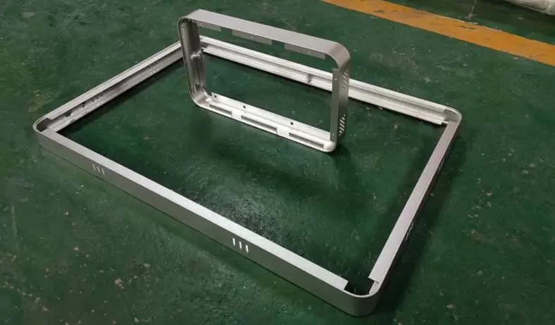
The body of J75-200 closed double-point high-speed precision press adopts a split frame structure, which is composed of upper beam, left and right columns, and base. The split connection method of the machine adopts the hydraulic pre-tightening technology of four tensioning screws, and adopts the structure of four-point support type eccentric shaft. , The guide around the slider adopts the composite structure of linear ball guide post and alloy copper bushing, equipped with a balance slider type dynamic balance mechanism, and a set of balance cylinder system. The photo of the machine appearance is shown in Figure 1. Main Specifications:
- Nominal force 2000kN; stroke times 200~400spm;
- Slider stroke 30mm; maximum die height 420mm;
- Die height adjustment
- 50mm; machine weight 40t.
- J75-200 closed double point high speed precision press
When carrying out the 3D modeling and assembly of the digital virtual prototype, it is necessary to fully consider that the digital model can truly reflect the behavior characteristics of the actual engineering prototype, so that the digital model can analyze the kinematics and dynamic performance of the mechanical system, and at the same time Simulation results can also be used for modal analysis, fatigue analysis, finite element analysis and optimization design of typical parts. Minimize compression or simplification of fillets, holes, seal grooves, etc., unless they fail during part meshing and no further finite element analysis of the part is possible. The correct material properties should be given to the parts to ensure the correctness of the analysis results, and the direction of gravity should be paid attention to when setting the simulation conditions.
The Relationship Between The Weight Change Of The Dynamic Balance Block And The Unbalanced Inertial Force Change
Set the working conditions of the digital prototype: fix the upper die with a weight of 1000kg on the bottom of the slider, and the initial weight of the prepared balance slider is 1305kg, exhaust the compressed air in the balance cylinder, so that the tension of the balance cylinder is zero, and the machine tool is running idly Under the conditions of 400min-1 stroke times, the slider starts to move from the top dead center, and the vertical upward direction is the positive direction. After running the Simulation software, obtain the displacement, velocity and acceleration of the slider in the vertical direction.
The above simulation results show that the displacement value of the slider in the vertical direction (y direction) is 30mm, which is the stroke length of the slider. The maximum vertical movement speed of the slider is 627.26mm/s, which occurs at the crankshaft angle of 90° and 270° respectively according to the time point, and the maximum vertical movement acceleration of the slider is 27053mm/s2, which occurs at the top dead center and the bottom dead center position.
The unbalanced inertial force (that is, the equivalent inertial force) of the slider, balance slider, connecting rod, eccentric shaft and other moving mechanisms acts on the upper beam bearing seat through the crankshaft, and the equivalent inertial force can be considered to be determined by the fixed value and the change amount composition. The fixed value of the unbalanced inertial force will cause the vibration of the machine body when the high-speed precision press starts, stops or changes in speed. After the working speed of the slider is stabilized, the fixed value of the equivalent inertial force has little effect on the vibration of the press. . The main factor that causes the up and down vibration of the press is the change in the vertical component of the equivalent inertial force that periodically changes in size and direction during the operation. The shock-absorbing pads and the ground generate vibration.
The reaction force acting on the bearing seat obtained after the motion simulation of the digital prototype can reflect the distribution law of the equivalent inertial force of the kinematic mechanism in each operation cycle and the inertial force balance effect of the whole machine. The magnitude and periodic variation of the vertical reaction force component in a motion cycle reflects the change of the unbalanced inertial force of the high-speed precision press. The motion simulation results of the vertical direction reaction force component of the bearing seat are exported to EXCEL and prepared. into a curve, which can intuitively reflect the periodic variation of the unbalanced inertial force. Figure 5 reflects the variation law of the unbalanced inertial force variation in one cycle. The maximum value of the unbalanced inertial force occurs at the bottom dead center moment, and the value is 68519N, and the minimum value occurs at the top dead center moment, and the value is 39452N.
In 0.150s of a running cycle, the change of inertial force reaches 29057N, which indicates that the imbalance of the crank-slider mechanism is serious. The change of the weight of the balance slider corresponds to the change of the unbalanced inertial force. In order to find the weight of the dynamic balance slider that can minimize the change of the unbalanced force in the vertical direction, let the weight of the dynamic balance slider be 30kg. In order to increase the variable, the change value of the y-direction reaction force of the bearing seat corresponding to the weight of the different balanced sliders in a movement cycle, that is, the change of the unbalanced inertial force of the machine tool when the slider moves, is obtained through motion simulation, and is drawn as a chart .
The curve of the change of unbalanced inertial force is V-shaped, that is, when the weight of the slider and the upper die is constant, the changing weight of the dynamically balanced slider corresponds to a minimum value of the change of the unbalanced inertial force, which can make the unbalanced inertial force The value of the change is the smallest, and the balance effect is the best, and the corresponding weight of the dynamic balance slider is the optimal value we hope to obtain. In Figure 6, when the weight of the dynamic balance block is 1635kg, the unbalanced inertia force change corresponding to the press with a 1000kg upper die is only 595N, which corresponds to the unbalanced inertia when the weight of the dynamic balance block is 1305kg. Compared with 29067N, the force change has decreased by 98%. The periodic variation of the unbalanced inertial force of 595N is negligible for a press with a dead weight of about 40t, that is to say, the press has achieved a good dynamic balance effect. Figure 7 shows the change of unbalanced inertial force in one cycle of the press obtained by motion simulation after optimizing the weight of the dynamic balance slider.
High-speed precision presses are equipped with ever-changing molds in the actual application process. Different upper mold weights require corresponding dynamic balance weights that can minimize the change in unbalanced inertial force. Through motion simulation, the relationship data of the unbalanced inertial force change, the weight change of the upper die and the weight of the dynamic balance slider under the optimal matching conditions of the digital prototype can be obtained. According to the motion simulation results shown in Figure 9, it can be derived as follows
- m1=km2+m3 (1)
- In the formula: m1——the weight of the dynamic balance slider;
- m2——the weight of the upper die;
- m3——the optimal initial weight when the dynamic balance slider is not equipped with the upper die;
- k is the slope.
For a press with a balanced slider type dynamic balance structure, the k value varies with the structural shape and parameters of the press slider system and dynamic balance slider system. The ratio of the eccentricity of the dynamic balance eccentric shaft at the main connecting rod to the eccentricity of the auxiliary connecting rod is the main factor affecting the slope, and the slope is also related to the position of the center of mass of the slider system and the dynamic balance slider system.
In this digital model, m3 is 1035kg and k is 0.6. When the weight of the mold (upper mold) is 500kg, the weight m1 of the dynamic balance slider is obtained as:
m1=0.6×500+1035=1335kg
According to formula (1), when the press is installed with a mold with an upper mold weight of 500kg, if the weight of the adjustable dynamic balance slider is adjusted to 1335kg, the balance slider type dynamic balance device will achieve the best balance effect. .
For high-speed presses with adjustable auxiliary slider weight, the manufacturer should provide the k value of different models to customers to guide the rapid adjustment of the dynamic balance slider during actual use, so as to ensure the smooth operation of the press.
The Relationship Between The Speed Change Of Unbalanced Inertial Force Slider And The Change
The design requires that the high-speed precision press can work smoothly within the range of the allowable number of strokes. The best balance effect of the high-speed press at the highest stroke number has been achieved. Is the dynamic balance system still effective when the number of strokes is reduced? Carry out the motion simulation of the digital model of the high-speed press under the conditions of different strokes to observe the dynamic balance. It is assumed that the digital virtual prototype is equipped with a 1000kg upper die, the weight of the dynamic balance slider is adjusted to 1635kg, the number of strokes is started from 200min-1, and a simulation analysis is carried out for every 25min-1 increase.
The kinematic simulation results show that the number of slider strokes from the minimum 200min-1 change to the maximum allowable value 400min-1the change in the unbalanced inertial force of the press is from 149N change to 595N, the amount of change shows an increasing trend, but within an acceptable range. It can be considered that there is no obvious correlation between the change value of the unbalanced inertial force and the rotational speed. Once the optimal matching weight of the dynamic balance slider under a certain number of strokes is determined, it can meet the requirements of the entire allowable speed regulation range of the press. Dynamic balance requirements.
The Role Of The Balance Cylinder
Assuming that the slider is pulled by a balancing cylinder of 40000N and runs for 400min-1, the counterweight still takes the optimal value of 1635kg. The motion simulation results show that the value of the periodic variation of the unbalanced inertial force is 595N, which is exactly equal to the variation of the unbalanced inertial force without the balance cylinder. That is to say, changing the tension of the balancing cylinder by adjusting the air pressure change of the balancing cylinder does not affect the variation of the unbalanced inertial force of the pressure-dynamic balancing system. From this point of view, if the press is equipped with upper dies of different weights, it is advisable to adjust the weight of the dynamic balance slider to obtain the best balance point instead of simply relying on adjusting the air pressure of the balance cylinder to achieve the balance effect.
Although the tension of the balance cylinder cannot significantly affect the periodic variation of the unbalanced inertial force, it can affect the absolute value of the unbalanced inertial force. Figure 11 shows the motion simulation results of two different situations with and without the balance cylinder tension. With a balancing cylinder pull of 40000N, the vertical unbalanced inertial force of the press is reduced by 40000N throughout the simulation cycle. For example, at the top dead center position, it drops from 56620N without the tension of the balance cylinder to 16620N. If the press is allowed to install a larger diameter and more balance cylinders, the tension of the balance cylinder is greater than the unbalanced inertial force and self-weight of the dynamic balance slider, slider, crankshaft and other motion systems on the press, so that the tension of the balance cylinder is in excess. The compensation state will help to maintain the unidirectional clearance of the slider system and improve the accuracy of the bottom dead center. Otherwise, the tension of the balance cylinder will not be zero. In addition, in the press described in this article, the slider volume is relatively large, and the number of strokes is not too high. The maximum moving speed of the balance cylinder piston is calculated to be 627.26mm/s. Within the range that the pneumatic seal can withstand, a balance cylinder should be configured. system. Appropriate balance cylinder or balance air bag can also improve the working conditions of the mold height adjustment motor and facilitate the debugging of the mold.
Inertia Force In The Horizontal Direction
The high-speed precision press has vertical inertial force and horizontal inertial force in motion. When the number of slider strokes increases, the horizontal inertial force increases significantly. Under normal circumstances, the action point of the horizontal inertia force is far away from the vibration damping and damping seat, and the periodic change of the moment easily causes the press to sway back and forth. The auxiliary slider balance mechanism has a significant effect on reducing the inertia force change in the vertical direction, but it cannot completely solve the inertia force balance problem in the horizontal direction.
The eccentric shaft structure in the digital model is optimized, and the eccentric shaft is equipped with a suitable reverse balance block and then the motion simulation is carried out to obtain the numerical value and variation law of the inertial force in the horizontal direction. The comparison results before and after are shown in Figure 12. The simulation results show that the dynamic balance of the eccentric shaft itself has a significant impact on the horizontal inertial force. If you want to reduce the horizontal inertial force, you should focus on the dynamic balance effect of the eccentric shaft itself.
In Conclusion
Use SolidWorks software to establish a digital virtual prototype of a high-speed precision press; use the Simulation plug-in to carry out motion simulation of the crank-slider mechanism and the balance-slider type dynamic balancing device, which can predict the inertia force balance in the design stage and optimize the auxiliary slider balance mechanism , shorten the design cycle, improve design efficiency and design quality. It can guide the adjustment direction of the dynamic balance slider in the debugging of the physical prototype and the actual production application.
The motion simulation results show that when the stamping die is fixed, the balance mechanism of the auxiliary slider has a weight of the auxiliary balance slider that can make the change of the unbalanced inertia force of the press to be the smallest. The adaptive adjustment of the weight of the auxiliary balance slider enables the high-speed precision press to adapt to the changes of various stamping dies during actual use, so as to achieve the smallest change in the unbalanced inertial force, thereby improving the stability of the press and the bottom dead center. High dynamic accuracy, improve the quality of stamping parts, prolong the service life of the mold, and reduce the failure rate of high-speed precision presses.
The setting of the balance cylinder is beneficial to maintain the unidirectionality of the clearance of the slider system, but the vibration phenomenon of the high-speed precision press cannot be improved only by adjusting the balance force. For high-speed precision presses using eccentric shafts or crankshafts, optimizing the unbalanced inertial force of the rotating shaft itself is the main means to reduce the horizontal swing of the press.
There are many reasons that affect the vibration of high-speed precision presses. The purpose of this paper is to analyze the change of the equivalent inertial force of the slider system under the condition of idling, and to discuss the design method of the dynamic balance system of high-speed precision presses. The effect of the nominal force has not been discussed yet. Motion simulation of a high-speed precision press. Using the digital virtual prototype, it is possible to further carry out dynamic analysis and static analysis under the action of nominal force, carry out modal analysis and fatigue analysis of the press, and guide the optimal design of components to obtain the best comprehensive design effect. With the continuous progress of science and technology, high-speed precision press technology will also be developed rapidly.

China Sheet Metal Fabrication Company
Sheet fabrication services for mild steel, high strength low alloy (HSLA) steel, cold/hot rolled steel, galvanized steel, stainless steel, aluminum, copper and brass. Capable of fabricating parts up to 12 ft. length and +/-0.001 in. tolerance. Various capabilities include contract manufacturing,custom stamping,edge rolling, forming,top laser cutting, roll bending and welding. Finishing and secondary services such as hardware installation, tapping, deburring, cleaning, heat treating, plating, anodizing and painting available. Sheet Metal Prototype and low to high volume production runs offered.
Suitable for commercial/residential architectural, aluminum brake shape parts, wall panel systems, brackets, general flashings, rails, call button plates and ship building component parts.If you want a specific material to be used in the sheet metal fabrication process, don’t hesitate to contact us!
-

Stainless Steel Sheet Metal Fabrication
-
Aluminum Sheet Metal Fabrication
-
Copper Sheet Metal Fabrication
-
Brass Sheet Metal Fabrication
-
Steel Sheet Metal Fabrication
-

Titanium Sheet Metal Fabrication
-
Galvanized Steel Sheet Metal Fabrication
-
Mild Steel Sheet Metal Fabrication
-
Bronze Sheet Metal Fabrication
Our Sheet Metal Fabrication Applications
Be-Cu prototype offers custom sheet metal fabrication for creating structures, machines, and parts that includes:


Our Case Studies Gallery Of Sheet Metal Fabrication Parts
If you need custom Sheet Metal Fabrication parts in China from a trusted supplier, look no further. Professional service from 10 to 100000+ parts,Whether you want a small series production or large quantities,Be-Cu Prototype scale precision Sheet Metal Fabrication services according to our customers needs, including pipe,plate and tube cutting. Contact us to see how we can help you! Get a quote today!
-
Sheet Metal Fabrication Injection Molding Machine Hopper
-
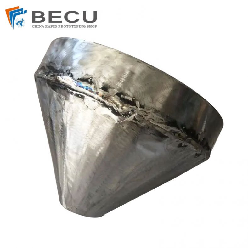
Sheet Metal Fabrication Funnel For Agricultural Machinery
-
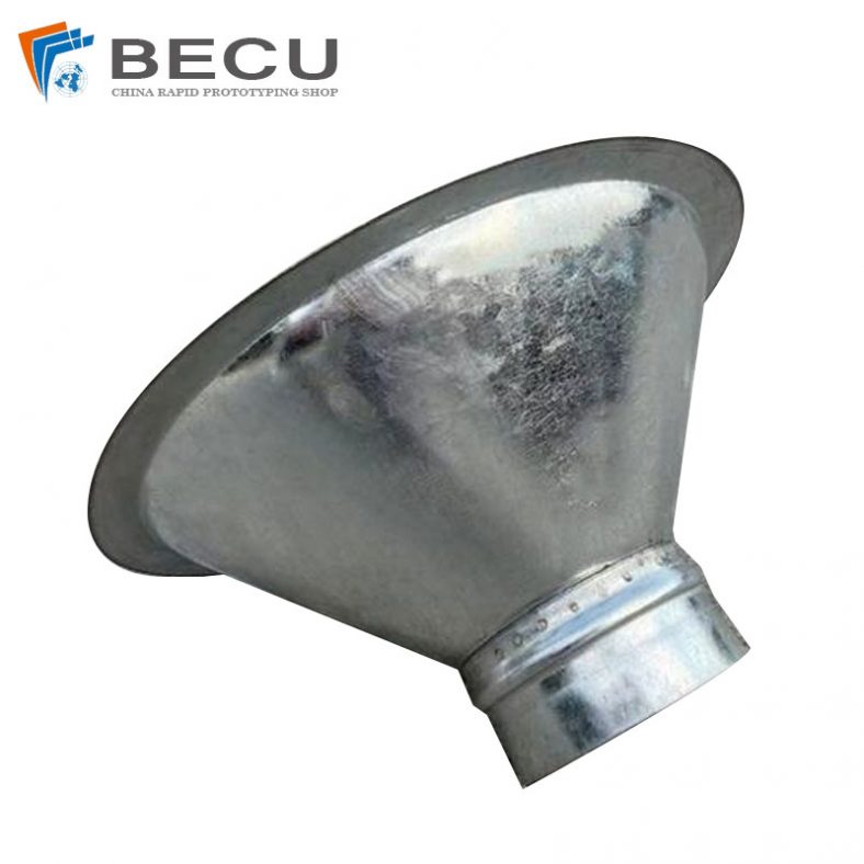
Sheet Metal Fabrication Galvanized Spiral Air Duct
-
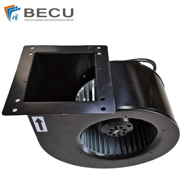
PCS Fan Ductwork Sheet Metal Housing
-
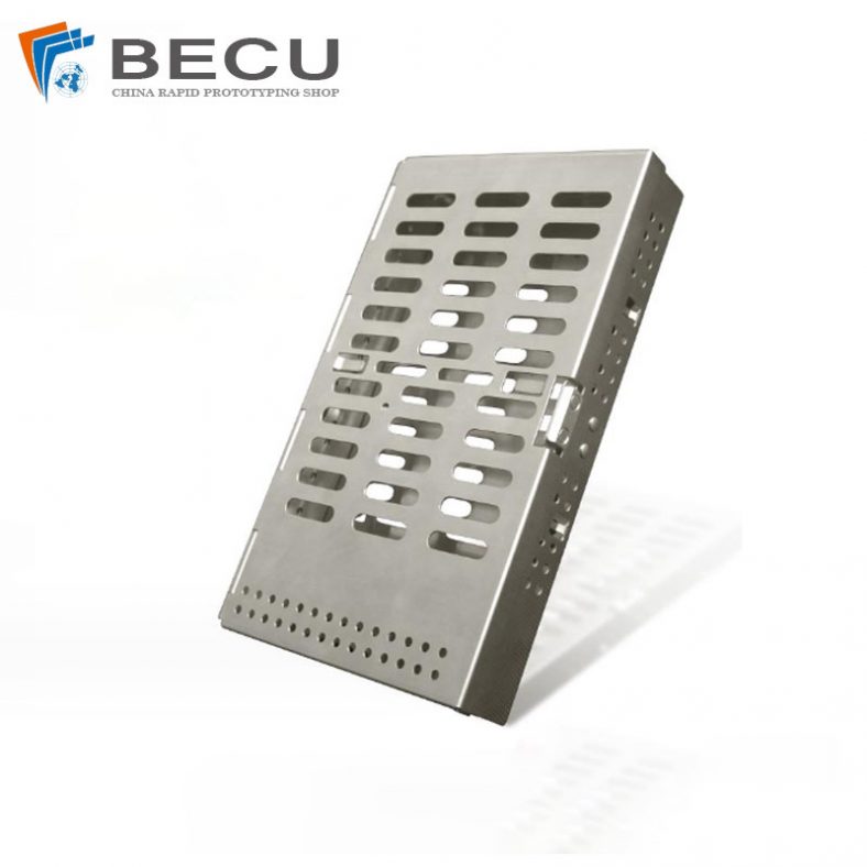
Custom Sheet Metal Surgical Instrument Sterilization Box For Beauty Salon
-

Precision Fabrication Green Energy EV Charging Station Cabinet
-
TA1TA2 Alloy Sheet Metal Manufacturing Machinery Support Parts
-

Sheet Metal Fabrication Aluminum 5052 Medical Box For Fire Fighting