
In the process of precision high-speed blanking, due to the constant friction between the die cutting edge and the material, the surface geometry of the cutting edge is easily changed, resulting in changes in the quality, size and shape of the blanking part, especially in large-scale high-speed stamping. During the process, edge wear has a greater impact on the dimensional consistency of blanking parts. Therefore, seeking a reasonable blanking gap design in the design stage is of great significance for reducing the internal stress of the mold, alleviating the mold wear and prolonging the service life of the cutting edge.
View Our Stamping Parts:
The “3C” industry represented by computer (Communication) and consumer electronics (Consumer Electronics) is a sunrise industry in today’s society. Connectors, connectors, shrapnel, terminals and other metal parts in 3C products are the basic parts of 3C products. Such metal parts have ultra-thin material thickness (below millimeter level), complex shape and small size, shape and shape. The position accuracy is very high (the dimensional accuracy is required to be close to the micron level), and the production batch is very large. It is usually produced by precision high-speed progressive stamping technology. Precision high-speed progressive stamping is to install a pair of precision, complex and progressive stamping dies including punching, bending, deep drawing, forming and other processes on a high-speed punching machine.
A stamping production method for efficient, mass production. Precision high-speed progressive stamping integrates precision manufacturing, computer technology, intelligent control and green manufacturing. It is an advanced manufacturing technology with high efficiency and high precision, representing the development level and direction of precision stamping technology. 10 kinds of molds including multi-station progressive molds have been included in the “Technical Progress and Technical Transformation Investment Direction of Equipment Manufacturing Industry (2010)” issued by the Ministry of Industry and Information Technology as key encouraged development projects. The “Twelfth Five-Year Plan” of the mold industry In the development plan, high-speed running, long-life precision multi-position progressive molds are also regarded as one of the key directions of product development.
With the dual challenges of enterprise capacity expansion and cost increase, the speed of progressive stamping dies is getting higher and higher, and precision high-speed progressive stamping technology has received extensive attention at home and abroad. The continuous improvement of stamping speed has brought great difficulties to the design and manufacture of precision high-speed stamping dies and high-speed stamping forming. /min There are still many key technologies in domestic high-speed progressive stamping technology to be broken through. This research focuses on blanking parts with different contours, from the perspective of optimizing the blanking gap to obtain the minimum punch stress and alleviating the wear of precision high-speed stamping dies. Explore the design technology of precision high-speed stamping dies and apply them to the field of precision high-speed stamping of actual terminal parts.
Stress Analysis During High-Speed Punching
In the process of high-speed blanking, there are mainly four places where the contact between the die and the plate occurs.
- Between the end face of the convex and concave die and the plate
- Between the side wall of the convex and concave die and the plate
- After the plate is broken and separated, between the waste and the during the pushing process, the waste and the side wall of the mould between.
There is a gap between the convex and the concave die, and the force Pp of the convex die and the force Pd of the concave die do not coincide, which will inevitably produce a force couple that twists the sheet. Therefore, the actual contact area between the convex and concave die surfaces and the plate is only limited to a narrow area near the edge of the blade. As shown in Figure 1, the length of the actual contact narrow strip is assumed to be the distribution of the pressure acting on it in a right-angled triangle. Then the distance between 0 and Pd is 2b + c, and when all the punching force is applied in the narrow zone of actual contact, the sheet will be compressed and deformed and plastic flow will occur. There is relative sliding between the flowing material and the mold, creating friction. The size of the friction force will depend on Pp, Pd and lubrication conditions, that is, the ratio of the convex and concave die gap to the material thickness (c/t0), the friction coefficients u1, u2, and the direction of the friction force depends on the direction of the material’s plastic flow.
Studies have shown that increasing the lubrication to reduce the friction on the side of the cutting edge is equivalent to reducing the tensile stress acting on the sheet material on the cutting edge, thus delaying the appearance of cracks, reducing the fillet band and increasing the bright band.
At the same time, The frictional force acting on the sidewall and end face of the die edge will cause the die to wear, but the side pressure on the punch during the punching process is much greater than that of the die, so the sidewall and end face of the punch are most prone to wear, and the die is most prone to wear. There is a certain linear relationship between wear and the internal stress of the mold. In this study, the stress state of the punch during the high-speed blanking process is taken as the research object, and the minimum punch internal stress of the punched parts with different contours is the optimization goal, and finally a reasonable non-uniform blanking gap is obtained, which is verified by the die test.
Influence Of Blanking Gap On Internal Stress Of Punch
The influence curve of blanking gap on punch internal stress (material is AISI 1010, material thickness is 0.8mm, punching speed is 600 times/min) is shown in Figure 2. It can be seen from the figure that with the increase of the blanking gap, the internal stress of the punch decreases significantly, but after the blanking gap continues to increase to a certain extent, the internal stress of the punch increases gradually, so that the internal stress of the punch increases with the increase of the blanking gap.
With the increase of the blanking gap, a “V”-shaped curve appears, indicating that there is a reasonable blanking gap range in the blanking process, and it is theoretically possible to optimize the blanking gap with the goal of obtaining the minimum punch internal stress.
Blanking Gap Optimization For Different Contours
The blanking contour of general blanking parts can be divided into four basic shapes, round, straight edge, rounded corner, and rectangle (straight edge + rounded corner). To this end, a finite element model of four basic shapes of blanking contours (Fig. 3) was established to carry out numerical simulation analysis of different blanking gaps to obtain the average stress level of punches with different blanking contours under different blanking gaps.
The simulation results are shown in Figure 4. When different contours are punched, the average internal stress of the punch varies with the blanking gap, showing a “V” or “U” shape, indicating that there are reasonable blanking when different contours are punched. However, the actual blanking profile is several couplings of these four basic profiles, and the optimal clearance for each profile is different. How to optimize the blanking clearance for complex profiles is the actual production of precision high-speed stamping enterprises. required.
Design Of Non-Uniform Blanking Gap And Die Test Verification
Starting from the results of the previous simulation analysis and the design idea of the non-uniform blanking gap, the die design for the blanking part as shown in Figure 5 is completed (the sheet material is AISI 1010, and the material thickness is 0.8 mm)
The wear conditions of punching punches in different mass production stages are shown in Figure 6. It can be clearly seen from the figure that the wear of the punch punched with non-uniform clearance is significantly improved compared with the traditional punching with uniform clearance. It is preliminarily verified that its normal service life can be increased by more than 3 times.
Concluding Remarks
Through the analysis of the friction between the die and the sheet metal, it is determined that the edge of the punch is most prone to wear failure, and there is a linear relationship between the wear of the punch and the internal stress of the punch during the blanking process.
In this paper, by means of numerical simulation, the average internal stress of punches with different shapes and contours at different blanking gaps is obtained, and the internal relationship between the blanking gap and the internal stress of the punches for blanking parts with complex contours is discussed. The non-uniform blanking gap optimization design idea of punch internal stress has been verified by experiments to significantly improve the service life of the mold.
China Sheet Metal Fabrication Company
Sheet fabrication services for mild steel, high strength low alloy (HSLA) steel, cold/hot rolled steel, galvanized steel, stainless steel, aluminum, copper and brass. Capable of fabricating parts up to 12 ft. length and +/-0.001 in. tolerance. Various capabilities include contract manufacturing,custom stamping,edge rolling, forming,top laser cutting, roll bending and welding. Finishing and secondary services such as hardware installation, tapping, deburring, cleaning, heat treating, plating, anodizing and painting available. Sheet Metal Prototype and low to high volume production runs offered.
Suitable for commercial/residential architectural, aluminum brake shape parts, wall panel systems, brackets, general flashings, rails, call button plates and ship building component parts.If you want a specific material to be used in the sheet metal fabrication process, don’t hesitate to contact us!
-
Stainless Steel Sheet Metal Fabrication
-
Aluminum Sheet Metal Fabrication
-
Copper Sheet Metal Fabrication
-
Brass Sheet Metal Fabrication
-
Steel Sheet Metal Fabrication
-
Titanium Sheet Metal Fabrication
-
Galvanized Steel Sheet Metal Fabrication
-
Mild Steel Sheet Metal Fabrication
-
Bronze Sheet Metal Fabrication
Our Sheet Metal Fabrication Applications
Be-Cu prototype offers custom sheet metal fabrication for creating structures, machines, and parts that includes:
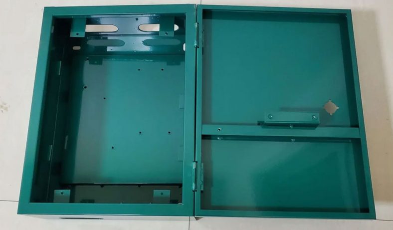
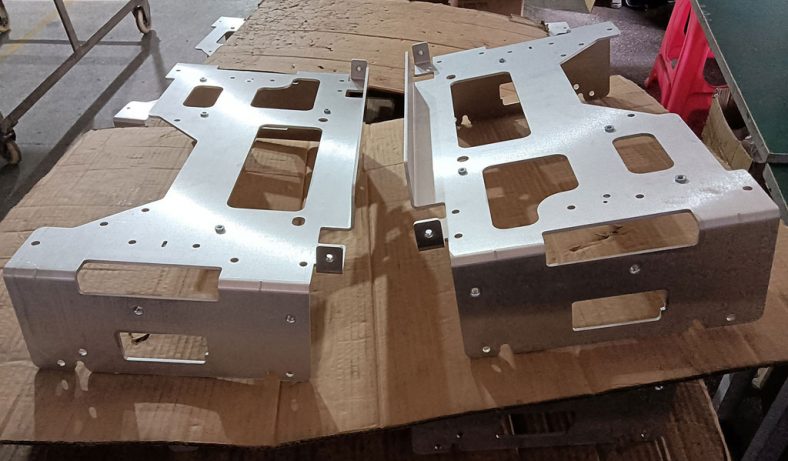
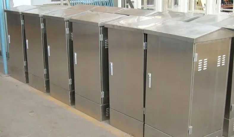
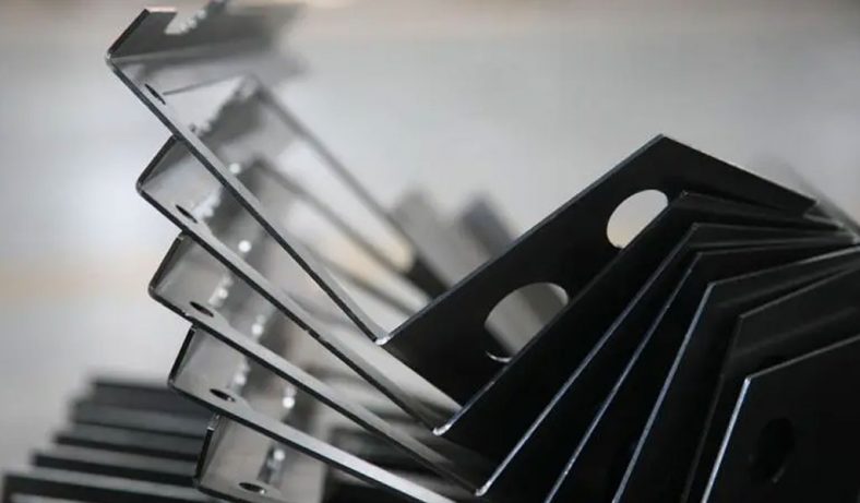
Our Case Studies Gallery Of Sheet Metal Fabrication Parts
If you need custom Sheet Metal Fabrication parts in China from a trusted supplier, look no further. Professional service from 10 to 100000+ parts,Whether you want a small series production or large quantities,Be-Cu Prototype scale precision Sheet Metal Fabrication services according to our customers needs, including pipe,plate and tube cutting. Contact us to see how we can help you! Get a quote today!
-
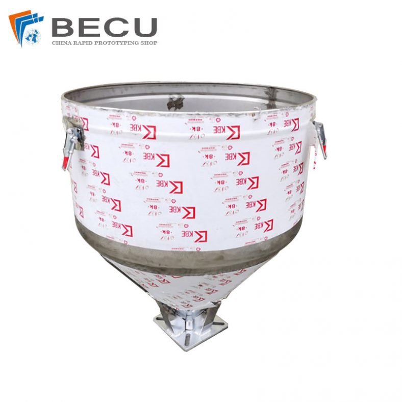
Sheet Metal Fabrication Injection Molding Machine Hopper
-
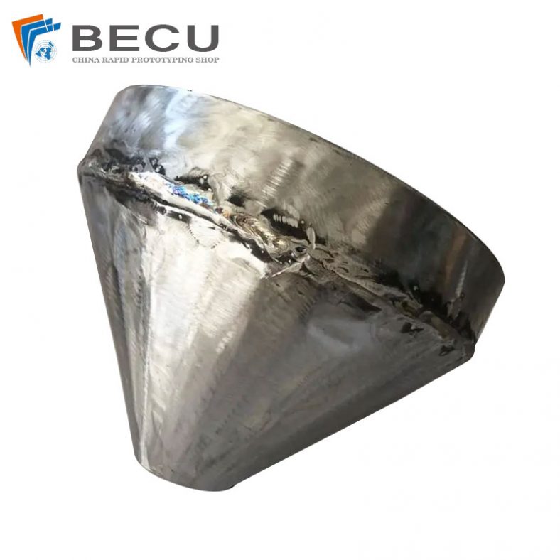
Sheet Metal Fabrication Funnel For Agricultural Machinery
-
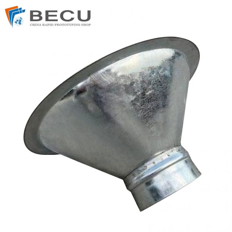
Sheet Metal Fabrication Galvanized Spiral Air Duct
-
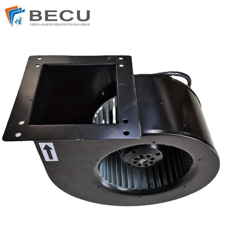
PCS Fan Ductwork Sheet Metal Housing
-
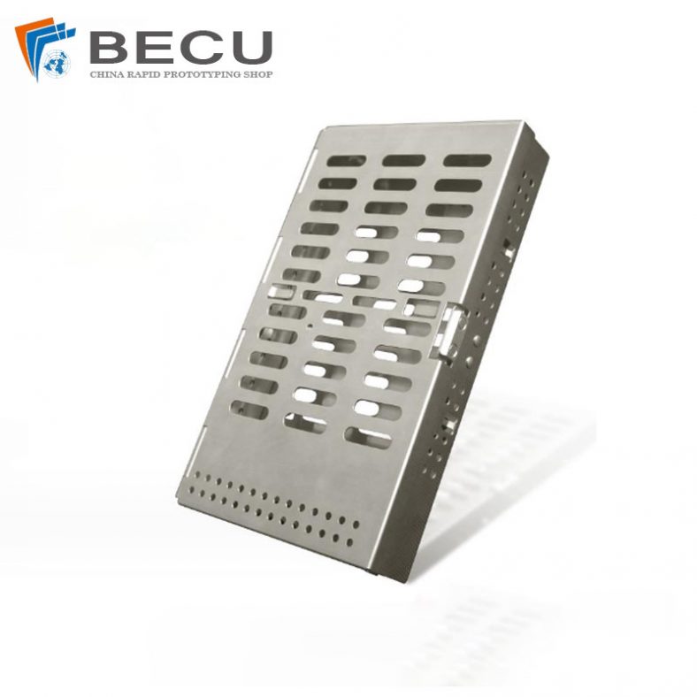
Custom Sheet Metal Surgical Instrument Sterilization Box For Beauty Salon
-
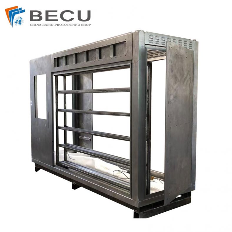
Precision Fabrication Green Energy EV Charging Station Cabinet
-
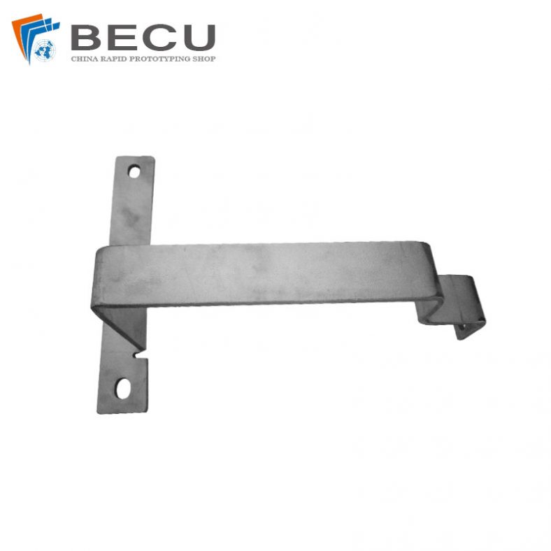
TA1TA2 Alloy Sheet Metal Manufacturing Machinery Support Parts
-

Sheet Metal Fabrication Aluminum 5052 Medical Box For Fire Fighting